LED cubes are a fascinating item, no matter where you come from the allure of blinking LEDs in various patterns is always attractive. And making your own is a fun challenge that most people can do after some experience with electronics hardware. However most people use single-colour LEDs, as wiring up RGB units triples the complexity of the circuit. Until now.
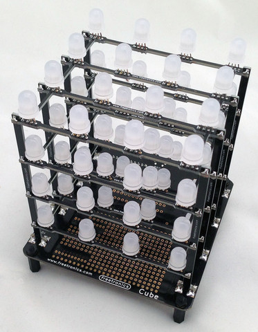
After much anticipation Freetronics have released their CUBE4 RGB LED cube kit – a simple to assemble and completely-customisable RGB LED cube:
Unlike other cubes on the market, this one includes an on-board ATmega32u4 microcontroller with Arduino Leonardo-compatible bootloader and a microUSB socket (… and a lot more) – so you don’t need anything extra to get started. And this gives you many more options when you’re ready to expand. But first let’s put it together and then get it working. Furthermore, keep reading to find out how you can have a chance to win your own Cube4.
Assembly
Inside the box are all the parts needed for the kit, even a microUSB cable to power the Cube4 and also communicate with it:
There’s 64 RGB LEDs in that bag, so get ready for some soldering. The base PCB is well laid out, labelled and gives you an idea for the expansion possibilities:
Plenty of room to add your own circuitry – and the bottom:
As you can see in the image above, there’s an XBee-compatible pinout if you want to add communication via wirless serial link, plenty of prototyping space for your own additions and many other ports are brought out to open pads. There’s even a 5V supply pair to test LEDs, and a blue “power on” LED (which can be deactivated if necessary by cutting a track on the PCB).
The first job is to mount the LEDs on their plane PCBs – there are four, one for each horizontal plant. It’s very important to get the LEDs in the right way round, and there’s markers on the PCB that you can match up the longest leg of the LED with:
From experience I found it best to insert all the LEDs:
…and then do a final mass check of the alignment – which is easy if you hold the plane up to one side and compare the legs, for example:
At this stage it’s a great idea to double-check your LED alignment. After a while you’ll have the LEDs soldered in and trimmed nicely:
The next step was getting the vertical sticks aligned in order to hold the LED planes (above). Each stick is for a particular spot on the PCB so check the label on the stick matches the hole on the PCB. It’s incredibly important to make sure you have them perfectly perpendicular to the PCB, so find something like a square-edge or card to help out:
Once you have a row of sticks in you can start with a plane then insert a stick on the other side, for example:
Note the use of the elastic band to hold things together – they really help. Then it’s a simple matter of adding the planes and holding it together with another band:
… at which point you can do a final check that all the planes and sticks are inserted correctly. Then solder all the copper spots together and you’re done.
Don’t forget to turn the cube upside-down as there’s soldering to be done on the bottom of the planes as well:
Although it might look a little scary, the final assembly isn’t that difficult – just take your time so it’s right the first time. You can view the following video which describes the entire process:
Once you’re confident that all the soldering has been completed – double-check for joints that aren’t completely bridged with solder as they will affect the operation of the cube. Then you can plug in the USB cable and watch the preloaded test/demonstration sketch in action:
If all your LEDs are working, awesome. If not – check the soldering. If there’s still some rogues – check your individual LEDs. Some of you are probably thinking “well that isn’t too colourful” – the problem is the camera, not the Cube4. If you see it in real life, it’s much better.
Operation
There are two methods of controlling the Cube4. It is delivered with a preloaded sketch that runs the demonstration showed in the video above, and then accepts commands over a serial/USB connection. So you can simply plug it in, fire up a terminal program (or the Arduino IDE serial monitor) and send text commands to do various things. If you type “help ;” the syntax is returned which explains how you can do things (click image to enlarge):
This serial control mode allows control by any type of software that can write to a serial port. Furthermore any other external hardware that can create or introduce serial text can also control the Cube4. For example by mounting an XBee module underneath and linking it to the TX/RX lines gives you a wireless Cube4. By doing so you can control it with a Raspberry Pi or other system.
Furthermore the Cube4 is also an Arduino Leonardo-compatible board in the same way as a Freetronics LeoStick. With the use of the Cube4 Arduino library you can then create your own sketches which can visualise data with very simple to use functions for the Cube4. There are some great example sketches with the library for some inspiration and fun. Over time I look forward to using the Cube4 in various ways, including adding an Electric Imp IoT device and making another clock (!).
Competition
Would you like the chance to win a Cube4? It’s easy. Clearly print your email address on a postcard, and mail it to:
CUBE4 Competition, PO Box 5435, Clayton 3168, Australia
Entries must be received by the 30th of July 2013. One postcard will then be drawn at random, and the winner will receive one Cube4 delivered by Australia Post standard air mail. You can enter as many times as you like. We’re not responsible for customs or import duties, VAT, GST, postage delays, non-delivery or whatever walls your country puts up against receiving inbound mail.
This is the most approachable RGB LED cube kit on the market, and also the easiest to use. You don’t need to understand programming to try it out – and if you do it’s incredibly versatile. A lot of work has gone into the library, API and hardware design so you’ve got an expandable tool and not just some blinking LEDs. For more information visit the Freetronics website. Larger photos available on flickr. And if you made it this far – check out my new book “Arduino Workshop” from No Starch Press.
The CUBE4 in this review is a promotional consideration from Freetronics. In the meanwhile have fun and keep checking into tronixstuff.com. Why not follow things on twitter, Google+, subscribe for email updates or RSS using the links on the right-hand column? And join our friendly Google Group – dedicated to the projects and related items on this website. Sign up – it’s free, helpful to each other – and we can all learn something.
LED cubes are a fascinating item, no matter where you come from the allure of blinking LEDs in various patterns is always attractive. And making your own is a fun challenge that most people can do after some experience with electronics hardware. However most people use single-colour LEDs, as wiring up RGB units triples the complexity of the circuit. Until now.
After much anticipation Freetronics have released their CUBE4 RGB LED cube kit – a simple to assemble and completely-customisable RGB LED cube:
Unlike other cubes on the market, this one includes an on-board ATmega32u4 microcontroller with Arduino Leonardo-compatible bootloader and a microUSB socket (… and a lot more) – so you don’t need anything extra to get started. And this gives you many more options when you’re ready to expand. But first let’s put it together and then get it working. Furthermore, keep reading to find out how you can have a chance to win your own Cube4.
Assembly
Inside the box are all the parts needed for the kit, even a microUSB cable to power the Cube4 and also communicate with it:
There’s 64 RGB LEDs in that bag, so get ready for some soldering. The base PCB is well laid out, labelled and gives you an idea for the expansion possibilities:
Plenty of room to add your own circuitry – and the bottom:
As you can see in the image above, there’s an XBee-compatible pinout if you want to add communication via wirless serial link, plenty of prototyping space for your own additions and many other ports are brought out to open pads. There’s even a 5V supply pair to test LEDs, and a blue “power on” LED (which can be deactivated if necessary by cutting a track on the PCB).
The first job is to mount the LEDs on their plane PCBs – there are four, one for each horizontal plant. It’s very important to get the LEDs in the right way round, and there’s markers on the PCB that you can match up the longest leg of the LED with:
From experience I found it best to insert all the LEDs:
…and then do a final mass check of the alignment – which is easy if you hold the plane up to one side and compare the legs, for example:
At this stage it’s a great idea to double-check your LED alignment. After a while you’ll have the LEDs soldered in and trimmed nicely:
The next step was getting the vertical sticks aligned in order to hold the LED planes (above). Each stick is for a particular spot on the PCB so check the label on the stick matches the hole on the PCB. It’s incredibly important to make sure you have them perfectly perpendicular to the PCB, so find something like a square-edge or card to help out:
Once you have a row of sticks in you can start with a plane then insert a stick on the other side, for example:
Note the use of the elastic band to hold things together – they really help. Then it’s a simple matter of adding the planes and holding it together with another band:
… at which point you can do a final check that all the planes and sticks are inserted correctly. Then solder all the copper spots together and you’re done.
Don’t forget to turn the cube upside-down as there’s soldering to be done on the bottom of the planes as well:
Although it might look a little scary, the final assembly isn’t that difficult – just take your time so it’s right the first time. You can view the following video which describes the entire process:
Once you’re confident that all the soldering has been completed – double-check for joints that aren’t completely bridged with solder as they will affect the operation of the cube. Then you can plug in the USB cable and watch the preloaded test/demonstration sketch in action:
If all your LEDs are working, awesome. If not – check the soldering. If there’s still some rogues – check your individual LEDs. Some of you are probably thinking “well that isn’t too colourful” – the problem is the camera, not the Cube4. If you see it in real life, it’s much better.
Operation
There are two methods of controlling the Cube4. It is delivered with a preloaded sketch that runs the demonstration showed in the video above, and then accepts commands over a serial/USB connection. So you can simply plug it in, fire up a terminal program (or the Arduino IDE serial monitor) and send text commands to do various things. If you type “help ;” the syntax is returned which explains how you can do things:
This serial control mode allows control by any type of software that can write to a serial port. Furthermore any other external hardware that can create or introduce serial text can also control the Cube4. For example by mounting an XBee module underneath and linking it to the TX/RX lines gives you a wireless Cube4. By doing so you can control it with a Raspberry Pi or other system.
Furthermore the Cube4 is also an Arduino Leonardo-compatible board in the same way as a Freetronics LeoStick. With the use of the Cube4 Arduino library you can then create your own sketches which can visualise data with very simple to use functions for the Cube4. There are some great example sketches with the library for some inspiration and fun. Over time I look forward to using the Cube4 in various ways, including adding an Electric Imp IoT device and making another clock (!).
This is the most approachable RGB LED cube kit on the market, and also the easiest to use. You don’t need to understand programming to try it out – and if you do it’s incredibly versatile. A lot of work has gone into the library, API and hardware design so you’ve got an expandable tool and not just some blinking LEDs. For more information visit the Freetronics website. Larger photos available on flickr. And if you made it this far – check out my new book “Arduino Workshop” from No Starch Press.
The CUBE4 in this review is a promotional consideration from Freetronics. In the meanwhile have fun and keep checking into tronixstuff.com. Why not follow things on twitter, Google+, subscribe for email updates or RSS using the links on the right-hand column? And join our friendly Google Group – dedicated to the projects and related items on this website. Sign up – it’s free, helpful to each other – and we can all learn something.
Over the last few years I’ve been writing a few Arduino tutorials, and during this time many people have mentioned that I should write a book. And now thanks to the team from No Starch Press this recommendation has morphed into my new book – “Arduino Workshop“:
Although there are seemingly endless Arduino tutorials and articles on the Internet, Arduino Workshop offers a nicely edited and curated path for the beginner to learn from and have fun. It’s a hands-on introduction to Arduino with 65 projects – from simple LED use right through to RFID, Internet connection, working with cellular communications, and much more.
Each project is explained in detail, explaining how the hardware an Arduino code works together. The reader doesn’t need any expensive tools or workspaces, and all the parts used are available from almost any electronics retailer. Furthermore all of the projects can be finished without soldering, so it’s safe for readers of all ages.
The editing team and myself have worked hard to make the book perfect for those without any electronics or Arduino experience at all, and it makes a great gift for someone to get them started. After working through the 65 projects the reader will have gained enough knowledge and confidence to create many things – and to continue researching on their own. Or if you’ve been enjoying the results of my thousands of hours of work here at tronixstuff, you can show your appreciation by ordering a copy for yourself or as a gift
You can review the table of contents, index and download a sample chapter from the Arduino Workshop website.
Arduino Workshop is available from No Starch Press in printed or ebook (PDF, Mobi, and ePub) formats. Ebooks are also included with the printed orders so you can get started immediately.
04/07/2013 – (my fellow) Australians – currently the easiest way of getting a print version is from Little Bird Electronics.
In the meanwhile have fun and keep checking into tronixstuff.com. Why not follow things on twitter, Google+, subscribe for email updates or RSS using the links on the right-hand column? And join our friendly Google Group – dedicated to the projects and related items on this website. Sign up – it’s free, helpful to each other – and we can all learn something.
Over the last few years I’ve been writing a few Arduino tutorials, and during this time many people have mentioned that I should write a book. And now thanks to the team from No Starch Press this recommendation has morphed into my new book – “Arduino Workshop“:
Although there are seemingly endless Arduino tutorials and articles on the Internet, Arduino Workshop offers a nicely edited and curated path for the beginner to learn from and have fun. It’s a hands-on introduction to Arduino with 65 projects – from simple LED use right through to RFID, Internet connection, working with cellular communications, and much more.
Each project is explained in detail, explaining how the hardware an Arduino code works together. The reader doesn’t need any expensive tools or workspaces, and all the parts used are available from almost any electronics retailer. Furthermore all of the projects can be finished without soldering, so it’s safe for readers of all ages.
The editing team and myself have worked hard to make the book perfect for those without any electronics or Arduino experience at all, and it makes a great gift for someone to get them started. After working through the 65 projects the reader will have gained enough knowledge and confidence to create many things – and to continue researching on their own. Or if you’ve been enjoying the results of my thousands of hours of work here at tronixstuff, you can show your appreciation by ordering a copy for yourself or as a gift
You can review the table of contents, index and download a sample chapter from the Arduino Workshop website.
Arduino Workshop is available from No Starch Press in printed or ebook (PDF, Mobi, and ePub) formats. Ebooks are also included with the printed orders so you can get started immediately.
In the meanwhile have fun and keep checking into tronixstuff.com. Why not follow things on twitter, Google+, subscribe for email updates or RSS using the links on the right-hand column? And join our friendly Google Group – dedicated to the projects and related items on this website. Sign up – it’s free, helpful to each other – and we can all learn something.
[Update 19/03/2013 - the project is now fully funded. When the boards arrive we'll do a full review]
Introduction
It’s a solid fact that there are quite a few variations on the typical Arduino Uno-compatible board. You can get them with onboard wireless, GSM, Zigbee and more – however all with their own issues and specific purposes. But what if you wanted a board that was physically and electrically compatible with an Arduino Uno – but with much more SRAM, more EEPROM, more flash, more speed – and then some? Well that (hopefully) will be a possibility with the introduction of the “Goldilocks” board on Pozible by Phillip Stevens.
What’s Pozible?
Pozible is the Australian version of Kickstarter. However just like KS anyone with a credit card or PayPal can pledge and support projects.
What’s a Goldilocks board?
It’s a board based around the Atmel ATmega1284p microcontroller in an Arduino Uno-compatible physical board with a microSD card socket and a few extras. The use of the ’1284p gives us the following advantages over the Arduino Uno, including:
16 kByte SRAM = 8x Uno SRAM – so that’s much more space for variables used in sketches – great for applications that use larger frame buffers such as Ethernet and image work;
2 kByte EEPROM = 2 x Uno EEPROM – giving you more space for non-volatile data storage on the main board;
128 kByte flash memory = 4 x Uno – giving you much, much more room for those larger sketches;
Two programmable USARTS – in other words, two hardware serial ports – no mucking about with SoftwareSerial and GSM or GPS shields;
Timer 3 – the ’1284p microcontroller has an extra 16-bit timer – timer 3, that is not present on any other ATmega microcontroller. Timer 3 does not have PWM outputs (unlike Timer 0, Timer 1, and Timer 2), and therefore is free to use as a powerful internal Tick counter, for example in a RTOS. freeRTOS has already been modified to utilise this Timer 3;
JTAG interface – yes – allowing more advanced developers the opportunity to debug their code;
better PWM access – the 1284p brings additional 8-bit Timer 2 PWM outputs onto PD, which creates the option for 2 additional PWM options on this port. It also removes the sharing of the important 16-bit PWM pins with the SPI interface, by moving them to PD4 & PD5, thus simplifying interface assignments;
Extra I/O pins – the 1284p has additional digital I/O pins on the PB port. These pins could be utilised for on-board Slave Select pins (for example), without stealing on-header digital pins and freeing the Arduino Pin 10 for Shield SPI SS use exclusively;
Furthermore the following design improvements over an Arduino Uno:
adding through-holes for all I/O – allowing you to solder directly onto the board whilst keeping header sockets;
replicate SPI and I2C for ease of use;
microSD card socket – that’s a no-brainer;
link the ATmega16u2 and ATmega1284p SPI interfaces – this will allow the two devices to work in concert for demanding multi-processing applications, involving USB and other peripherals;
Fully independent analogue pins, including seperate AVCC and GND – helps reduce noise on the ADC channels for improved analogue measurement accuracy;
move the reset button to the edge of the board – another no-brainer
clock the board at 20 MHz – that’s an extra 4 MHz over a Uno. And the use of a through hole precision crystal (not a SMD resonator) allows the use of after market timing choices, eg 22.1184 MHz for more accurate UART timings.
What does it look like?
At the moment the board mock-up looks like this:
If funding is successful (and we hope it will be) the Goldilocks will be manufactured by the team at Freetronics. Apart from being a world-leader in Arduino-compatible hardware and systems, they’re the people behind the hardware for Ardusat and more – so we know the Goldilocks will be in good hands.
Will it really be compatible?
Yes – the Goldilocks will be shipped pre-programmed with an Arduino compatible boot-loader, and the necessary Board description files will be available to provide a 100% compatible Arduino IDE experience.
Conclusion
If you think this kind of board would be useful in your projects, you want to support a good project – or both, head over to Pozible and make your pledge. And for the record – I’ve put my money where my mouth is
Please note that I’m not involved in nor responsible for the Goldilocks project, however I’m happy to promote it as a worthwhile endeavour. In the meanwhile have fun and keep checking into tronixstuff.com. Why not follow things on twitter, Google+, subscribe for email updates or RSS using the links on the right-hand column? And join our friendly Google Group – dedicated to the projects and related items on this website. Sign up – it’s free, helpful to each other – and we can all learn something.
Time for another instalment in my highly-irregular series of irregular clock projects. In this we have “Clock Four” – a scrolling text clock. After examining some Freetronics Dot Matrix Displays in the stock, it occurred to me that it would be neat to display the time as it was spoken (or close to it) – and thus this the clock was born. It is a quick project – we give you enough to get going with the hardware and sketch, and then you can take it further to suit your needs.
Hardware
You’ll need three major items – An Arduino Uno-compatible board, a real-time clock circuit or module using either a DS1307 or DS3232 IC, and a Freetronics DMD. You might want an external power supply, but we’ll get to that later on.
The first stage is to fit your real-time clock. If you are unfamiliar with the operation of real-time clock circuits, check out the last section of this tutorial. You can build a RTC circuit onto a protoshield or if you have a Freetronics Eleven, it can all fit in the prototyping space as such:
If you have an RTC module, it will also fit in the same space, then you simply run some wires to the 5V, GND, A4 (for SDA) and A5 (for SCL):
By now I hope you’re thinking “how do you set the time?”. There’s two answers to that question. If you’re using the DS3232 just set it in the sketch (see below) as the accuracy is very good, you only need to upload the sketch with the new time twice a year to cover daylight savings (unless you live in Queensland). Otherwise add a simple user-interface – a couple of buttons could do it, just as we did with Clock Two. Finally you just need to put the hardware on the back of the DMD. There’s plenty of scope to meet your own needs, a simple solution might be to align the control board so you can access the USB socket with ease – and then stick it down with some Sugru:
With regards to powering the clock – you can run ONE DMD from the Arduino, and it runs at a good brightness for indoor use. If you want the DMD to run at full, retina-burning brightness you need to use a separate 5 V 4 A power supply. If you’re using two DMDs – that goes to 8 A, and so on. Simply connect the external power to one DMD’s terminals (connect the second or more DMDs to these terminals):
The Arduino Sketch
You can download the sketch from here. It was written only for Arduino v1.0.1. The sketch has the usual functions to set and retrieve the time from DS1307/3232 real-time clock ICs, and as usual with all our clocks you can enter the time information into the variables in void setup(), then uncomment setDateDs1307(), upload the sketch, re-comment setDateDs1307, then upload the sketch once more. Repeat that process to re-set the time if you didn’t add any hardware-based user interface.
Once the time is retrieved in void loop(), it is passed to the function createTextTime(). This function creates the text string to display by starting with “It’s “, and then determines which words to follow depending on the current time. Finally the function drawText() converts the string holding the text to display into a character variable which can be passed to the DMD.
And here it is in action:
Conclusion
This was a quick project, however I hope you found it either entertaining or useful – and another random type of clock that’s easy to reproduce or modify yourself. We’re already working on another one which is completely different, so stay tuned.
In the meanwhile have fun and keep checking into tronixstuff.com. Why not follow things on twitter, Google+, subscribe for email updates or RSS using the links on the right-hand column? And join our friendly Google Group – dedicated to the projects and related items on this website. Sign up – it’s free, helpful to each other – and we can all learn something.
Time for another instalment in my highly-irregular series of irregular clock projects. In this we have “Clock Four” – a scrolling text clock. After examining some Freetronics Dot Matrix Displays in the stock, it occurred to me that it would be neat to display the time as it was spoken (or close to it) – and thus this the clock was born. It is a quick project – we give you enough to get going with the hardware and sketch, and then you can take it further to suit your needs.
Hardware
You’ll need three major items – An Arduino Uno-compatible board, a real-time clock circuit or module using either a DS1307 or DS3232 IC, and a Freetronics DMD. You might want an external power supply, but we’ll get to that later on.
The first stage is to fit your real-time clock. If you are unfamiliar with the operation of real-time clock circuits, check out the last section of this tutorial. You can build a RTC circuit onto a protoshield or if you have a Freetronics Eleven, it can all fit in the prototyping space as such:
If you have an RTC module, it will also fit in the same space, then you simply run some wires to the 5V, GND, A4 (for SDA) and A5 (for SCL):
By now I hope you’re thinking “how do you set the time?”. There’s two answers to that question. If you’re using the DS3232 just set it in the sketch (see below) as the accuracy is very good, you only need to upload the sketch with the new time twice a year to cover daylight savings (unless you live in Queensland). Otherwise add a simple user-interface – a couple of buttons could do it, just as we did with Clock Two. Finally you just need to put the hardware on the back of the DMD. There’s plenty of scope to meet your own needs, a simple solution might be to align the control board so you can access the USB socket with ease – and then stick it down with some Sugru:
With regards to powering the clock – you can run ONE DMD from the Arduino, and it runs at a good brightness for indoor use. If you want the DMD to run at full, retina-burning brightness you need to use a separate 5 V 4 A power supply. If you’re using two DMDs – that goes to 8 A, and so on. Simply connect the external power to one DMD’s terminals (connect the second or more DMDs to these terminals):
The Arduino Sketch
You can download the sketch from here. Please use IDE v1.0.1 . The sketch has the usual functions to set and retrieve the time from DS1307/3232 real-time clock ICs, and as usual with all our clocks you can enter the time information into the variables in void setup(), then uncomment setDateDs1307(), upload the sketch, re-comment setDateDs1307, then upload the sketch once more. Repeat that process to re-set the time if you didn’t add any hardware-based user interface.
Once the time is retrieved in void loop(), it is passed to the function createTextTime(). This function creates the text string to display by starting with “It’s “, and then determines which words to follow depending on the current time. Finally the function drawText() converts the string holding the text to display into a character variable which can be passed to the DMD.
And here it is in action:
Conclusion
This was a quick project, however I hope you found it either entertaining or useful – and another random type of clock that’s easy to reproduce or modify yourself. We’re already working on another one which is completely different, so stay tuned.
In the meanwhile have fun and keep checking into tronixstuff.com. Why not follow things on twitter, Google+, subscribe for email updates or RSS using the links on the right-hand column? And join our friendly Google Group – dedicated to the projects and related items on this website. Sign up – it’s free, helpful to each other – and we can all learn something.
This is a tutorial on using the MSGEQ7 Spectrum Analyser with Arduino, and chapter forty-eight of a series originally titled “Getting Started/Moving Forward with Arduino!” by John Boxall – A tutorial on the Arduino universe. The first chapter is here, the complete series is detailed here.
Updated 30/01/2013
In this article we’re going to explain how to make simple spectrum analysers with an Arduino-style board. (Analyser? Analyzer? Take your pick).
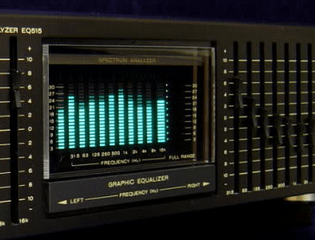
First of all, what is a spectrum analyser? Good question. Do you remember what this is?
It’s a mixed graphic equaliser/spectrum analyser deck for a hi-fi system. The display in the middle is the spectrum analyser, and roughly-speaking it shows the strength of different frequencies in the music being listened to – and looked pretty awesome doing it. We can recreate displays similar to this for entertainment and also as a base for creative lighting effects. By working through this tutorial you’ll have the base knowledge to recreate these yourself.
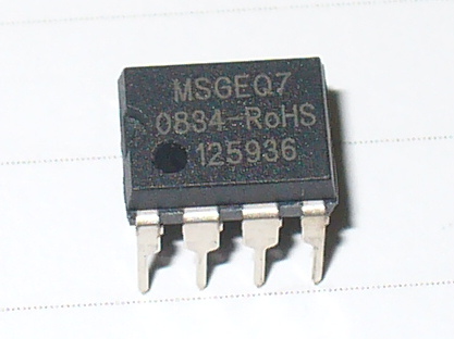
We’ll be using the MSGEQ7 “seven band graphic equaliser IC” from Mixed Signal Integration. Here’s the MSGEQ7 data sheet (.pdf). This little IC can accept a single audio source, analyse seven frequency bands of the audio, and output a DC representation of each frequency band. This isn’t super-accurate or calibrated in any way, but it works. You can get the IC separately, for example:
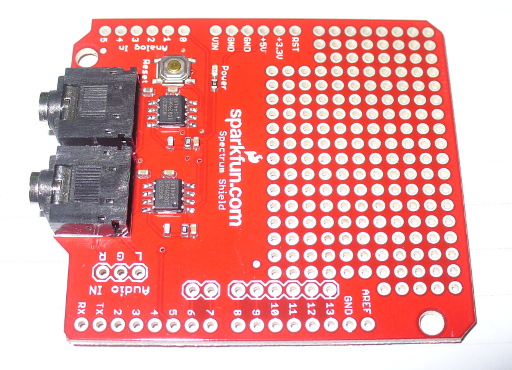
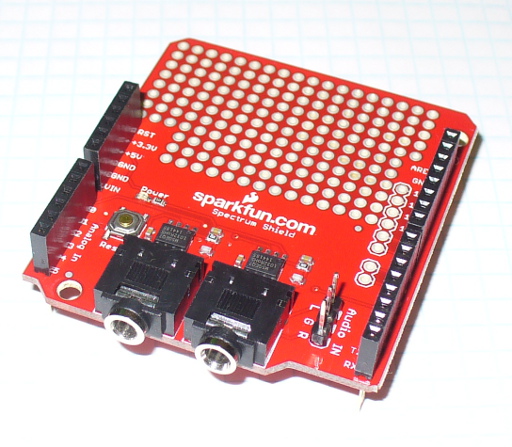
and then build your own circuit around it… or like most things in the Arduino world – get a shield. In this case, a derivative of the original Bliptronics shield by Sparkfun. It’s designed to pass through stereo audio via 3.5mm audio sockets and contains two MSGEQ7s, so we can do a stereo analyser:
As usual Sparkfun have saved a few cents by not including the stackable header sockets, so you’ll need to buy and solder those in yourself. There is also space for three header pins for direct audio input (left, right and common), which are useful – so if you can add those as well.
So now you have a shield that’s ready for use. Before moving forward let’s examine how the MSGEQ7 works for us. As mentioned earlier, it analyses seven frequency bands. These are illustrated in the following graph from the data sheet:
It will return the strengths of the audio at seven points – 63 Hz, 160 Hz, 400 Hz, 1 kHz, 2.5 kHz, 6.25 kHz and 16 kHz – and as you can see there is some overlap between the bands. The strength is returned as a DC voltage – which we can then simply measure with the Arduino’s analogue input and create a display of some sort. At this point audio purists, Sheldonites and RF people might get a little cranky, so once again – this is more for visual indication than any sort of calibration device.
However as an 8-pin IC a different approach is required to get the different levels. The IC will sequentially give out the levels for each band on pin 3- e.g. 63 Hz then 160 Hz then 400 Hz then 1 kHz then 2.5 kHz then 6.25 kHz then 16 kHz then back to 63 Hz and so on. To start this sequence we first reset the IC by pulsing the RESET pin HIGH then low. This tells the IC to start at the first band. Next, we set the STROBE pin to LOW, take the DC reading from pin 3 with analogue input, store the value in a variable (an array), then set the STROBE pin HIGH. We repeat the strobe-measure sequence six more times to get the rest of the data, then RESET the IC and start all over again. For the visual learners consider the diagram below from the data sheet:
To demonstrate this process, consider the function
readMSGEQ7()
in the following example sketch:
// Example 48.1 - tronixstuff.com/tutorials > chapter 48 - 30 Jan 2013
// MSGEQ7 spectrum analyser shield - basic demonstration
int strobe = 4; // strobe pins on digital 4
int res = 5; // reset pins on digital 5
int left[7]; // store band values in these arrays
int right[7];
int band;
void setup()
{
 Serial.begin(115200);
 pinMode(res, OUTPUT); // reset
 pinMode(strobe, OUTPUT); // strobe
 digitalWrite(res,LOW); // reset low
 digitalWrite(strobe,HIGH); //pin 5 is RESET on the shield
}
void readMSGEQ7()
// Function to read 7 band equalizers
{
 digitalWrite(res, HIGH);
 digitalWrite(res, LOW);
 for(band=0; band <7; band++)
 {
 digitalWrite(strobe,LOW); // strobe pin on the shield - kicks the IC up to the next band
 delayMicroseconds(30); //
 left[band] = analogRead(0); // store left band reading
 right[band] = analogRead(1); // ... and the right
 digitalWrite(strobe,HIGH);
 }
}
void loop()
{
 readMSGEQ7();
 // display values of left channel on serial monitor
 for (band = 0; band < 7; band++)
 {
 Serial.print(left[band]);
 Serial.print(" ");
 }
 Serial.println();
// display values of right channel on serial monitor
 for (band = 0; band < 7; band++)
 {
 Serial.print(right[band]);
 Serial.print(" ");
 }
 Serial.println();
}
If you follow through the sketch, you can see that it reads both left- and right-channel values from the two MSGEQ7s on the shield, then stores each value in the arrays left[] and right[]. These values are then sent to the serial monitor for display – for example:
If you have a function generator, connect the output to one of the channels and GND – then adjust the frequency and amplitude to see how the values change. The following video clip is a short demonstration of this – we set the generator to 1 kHz and adjust the amplitude of the signal. To make things easier to read we only measure and display the left channel:
Keep an eye on the fourth column of data – this is the analogRead() value returned by the Arduino when reading the 1khz frequency band. You can also see the affect on the other bands around 1 kHz as we increase and decrease the frequency. However that wasn’t really visually appealing – so now we’ll create a small and large graphical version.
First we’ll use an inexpensive LCD, the I2C model from akafugu reviewed previously. To save repeating myself, also review how to create custom LCD characters from here.
With the LCD with have two rows of sixteen characters. The plan is to use the top row for the levels, the left-channel’s on … the left, and the right on the right. Each character will be a little bar graph for the level. The bottom row can be for a label. We don’t have too many pixels to work with, but it’s a compact example:
We have eight rows for each character, and the results from an analogueRead() fall between 0 and 1023. So that’s 1024 possible values spread over eight sections. Thus each row of pixels in each character will represent 128 “units of analogue read” or around 0.63 V if the Arduino is running from true 5 V (remember your AREF notes?). The sketch will again read the values from the MSGEQ7, feed them into two arrays – then display the required character in each band space on the LCD.
Here’s the resulting sketch:
// Example 48.2 - tronixstuff.com/tutorials > chapter 48 - 30 Jan 2013
// MSGEQ7 spectrum analyser shield and I2C LCD from akafugu
// for akafugu I2C LCD
#include "Wire.h"
#include "TWILiquidCrystal.h"
LiquidCrystal lcd(50);
// create custom characters for LCD
byte level0[8] = { 0b00000, 0b00000, 0b00000, 0b00000, 0b00000, 0b00000, 0b00000, 0b11111};
byte level1[8] = { 0b00000, 0b00000, 0b00000, 0b00000, 0b00000, 0b00000, 0b11111, 0b11111};
byte level2[8] = { 0b00000, 0b00000, 0b00000, 0b00000, 0b00000, 0b11111, 0b11111, 0b11111};
byte level3[8] = { 0b00000, 0b00000, 0b00000, 0b00000, 0b11111, 0b11111, 0b11111, 0b11111};
byte level4[8] = { 0b00000, 0b00000, 0b00000, 0b11111, 0b11111, 0b11111, 0b11111, 0b11111};
byte level5[8] = { 0b00000, 0b00000, 0b11111, 0b11111, 0b11111, 0b11111, 0b11111, 0b11111};
byte level6[8] = { 0b00000, 0b11111, 0b11111, 0b11111, 0b11111, 0b11111, 0b11111, 0b11111};
byte level7[8] = { 0b11111, 0b11111, 0b11111, 0b11111, 0b11111, 0b11111, 0b11111, 0b11111};
int strobe = 4; // strobe pins on digital 4
int res = 5; // reset pins on digital 5
int left[7]; // store band values in these arrays
int right[7];
int band;
void setup()
{
 Serial.begin(9600);
 // setup LCD and custom characters
 lcd.begin(16, 2);
 lcd.setContrast(24);
 lcd.clear();
lcd.createChar(0,level0);
 lcd.createChar(1,level1);
 lcd.createChar(2,level2);
 lcd.createChar(3,level3);
 lcd.createChar(4,level4);
 lcd.createChar(5,level5);
 lcd.createChar(6,level6);
 lcd.createChar(7,level7);
 lcd.setCursor(0,1);
 lcd.print("Left");
 lcd.setCursor(11,1);
 lcd.print("Right");
 pinMode(res, OUTPUT); // reset
 pinMode(strobe, OUTPUT); // strobe
 digitalWrite(res,LOW); // reset low
 digitalWrite(strobe,HIGH); //pin 5 is RESET on the shield
}
void readMSGEQ7()
// Function to read 7 band equalizers
{
 digitalWrite(res, HIGH);
 digitalWrite(res, LOW);
 for( band = 0; band < 7; band++ )
 {
 digitalWrite(strobe,LOW); // strobe pin on the shield - kicks the IC up to the next band
 delayMicroseconds(30); //
 left[band] = analogRead(0); // store left band reading
 right[band] = analogRead(1); // ... and the right
 digitalWrite(strobe,HIGH);
 }
}
void loop()
{
 readMSGEQ7();
// display values of left channel on LCD
 for( band = 0; band < 7; band++ )
 {
 lcd.setCursor(band,0);
 if (left[band]>=895) { lcd.write(7); } else
 if (left[band]>=767) { lcd.write(6); } else
 if (left[band]>=639) { lcd.write(5); } else
 if (left[band]>=511) { lcd.write(4); } else
 if (left[band]>=383) { lcd.write(3); } else
 if (left[band]>=255) { lcd.write(2); } else
 if (left[band]>=127) { lcd.write(1); } else
 if (left[band]>=0) { lcd.write(0); }
 }
 // display values of right channel on LCD
 for( band = 0; band < 7; band++ )
 {
 lcd.setCursor(band+9,0);
 if (right[band]>=895) { lcd.write(7); } else
 if (right[band]>=767) { lcd.write(6); } else
 if (right[band]>=639) { lcd.write(5); } else
 if (right[band]>=511) { lcd.write(4); } else
 if (right[band]>=383) { lcd.write(3); } else
 if (right[band]>=255) { lcd.write(2); } else
 if (right[band]>=127) { lcd.write(1); } else
 if (right[band]>=0) { lcd.write(0); }
 }
}
If you’ve been reading through my tutorials there isn’t anything new to worry about. And now for the demo, with sound -
That would look great on the side of a Walkman, however it’s a bit small. Let’s scale it up by using a Freetronics Dot Matrix Display - you may recall these from Clock One. For some background knowledge check the review here. Don’t forget to use a suitable power supply for the DMD – 5 V at 4 A will do nicely. The DMD contains 16 rows of 32 LEDs. This gives us twice the “resolution” to display each band level if desired. The display style is subjective, so for this example we’ll use a single column of LEDs for each frequency band, with a blank column between each one.
We use a lot of line-drawing statements to display the levels, and clear the DMD after each display. With this and the previous sketches, there could be room for efficiency – however I write these with the beginner in mind. Here’s the sketch:
// Example 48.3 - tronixstuff.com/tutorials > chapter 48 - 30 Jan 2013
// MSGEQ7 spectrum analyser shield with a Freetronics DMD
// for DMD
#include "DMD.h" // for DMD
#include "SPI.h" // SPI.h must be included as DMD is written by SPI (the IDE complains otherwise)
#include "TimerOne.h"
#include "SystemFont5x7.h" // keep next two lines if you want to add some text
#include "Arial_black_16.h"
DMD dmd(1, 1); // creates instance of DMD to refer to in sketch
void ScanDMD() // necessary interrupt handler for refresh scanning of DMD
{
 dmd.scanDisplayBySPI();
}
int strobe = 4; // strobe pins on digital 4
int res = 5; // reset pins on digital 5
int left[7]; // store band values in these arrays
int right[7];
int band;
void setup()
{
 // for DMD
 //initialize TimerOne's interrupt/CPU usage used to scan and refresh the display
 Timer1.initialize( 5000 ); //period in microseconds to call ScanDMD. Anything longer than 5000 (5ms) and you can see flicker.
 Timer1.attachInterrupt( ScanDMD ); //attach the Timer1 interrupt to ScanDMD which goes to dmd.scanDisplayBySPI()
 dmd.clearScreen( true ); //true is normal (all pixels off), false is negative (all pixels on)

 // for MSGEQ7
 pinMode(res, OUTPUT); // reset
 pinMode(strobe, OUTPUT); // strobe
 digitalWrite(res,LOW); // reset low
 digitalWrite(strobe,HIGH); //pin 5 is RESET on the shield
}
void readMSGEQ7()
// Function to read 7 band equalizers
{
 digitalWrite(res, HIGH);
 digitalWrite(res, LOW);
 for( band = 0; band < 7; band++ )
 {
 digitalWrite(strobe,LOW); // strobe pin on the shield - kicks the IC up to the next band
 delayMicroseconds(30); //
 left[band] = analogRead(0); // store left band reading
 right[band] = analogRead(1); // ... and the right
 digitalWrite(strobe,HIGH);
 }
}
void loop()
{
 int xpos;
 readMSGEQ7();
 dmd.clearScreen( true );
 // display values of left channel on DMD
 for( band = 0; band < 7; band++ )
 {
 xpos = (band*2)+1;
 if (left[band]>=895) { dmd.drawLine( xpos, 15, xpos, 1, GRAPHICS_NORMAL ); } else
 if (left[band]>=767) { dmd.drawLine( xpos, 15, xpos, 3, GRAPHICS_NORMAL ); } else
 if (left[band]>=639) { dmd.drawLine( xpos, 15, xpos, 5, GRAPHICS_NORMAL ); } else
 if (left[band]>=511) { dmd.drawLine( xpos, 15, xpos, 7, GRAPHICS_NORMAL ); } else
 if (left[band]>=383) { dmd.drawLine( xpos, 15, xpos, 9, GRAPHICS_NORMAL ); } else
 if (left[band]>=255) { dmd.drawLine( xpos, 15, xpos, 11, GRAPHICS_NORMAL ); } else
 if (left[band]>=127) { dmd.drawLine( xpos, 15, xpos, 13, GRAPHICS_NORMAL ); } else
 if (left[band]>=0) { dmd.drawLine( xpos, 15, xpos, 15, GRAPHICS_NORMAL ); }
 }

 // display values of right channel on DMD
 for( band = 0; band < 7; band++ )
 {
 xpos = (band*2)+18;
 if (right[band]>=895) { dmd.drawLine( xpos, 15, xpos, 1, GRAPHICS_NORMAL ); } else
 if (right[band]>=767) { dmd.drawLine( xpos, 15, xpos, 3, GRAPHICS_NORMAL ); } else
 if (right[band]>=639) { dmd.drawLine( xpos, 15, xpos, 5, GRAPHICS_NORMAL ); } else
 if (right[band]>=511) { dmd.drawLine( xpos, 15, xpos, 7, GRAPHICS_NORMAL ); } else
 if (right[band]>=383) { dmd.drawLine( xpos, 15, xpos, 9, GRAPHICS_NORMAL ); } else
 if (right[band]>=255) { dmd.drawLine( xpos, 15, xpos, 11, GRAPHICS_NORMAL ); } else
 if (right[band]>=127) { dmd.drawLine( xpos, 15, xpos, 13, GRAPHICS_NORMAL ); } else
 if (right[band]>=0) { dmd.drawLine( xpos, 15, xpos, 15, GRAPHICS_NORMAL ); }
 }
}
… and here it is in action:
Conclusion
At this point you have the knowledge to use the MSGEQ7 ICs to create some interesting spectrum analysers for entertainment and visual appeal – now you just choose the type of display enjoy the results.
Have fun and keep checking into tronixstuff.com. Why not follow things on twitter, Google+, subscribe for email updates or RSS using the links on the right-hand column, or join our Google Group – dedicated to the projects and related items on this website. Sign up – it’s free, helpful to each other – and we can all learn something.
This is a tutorial on using the MSGEQ7 Spectrum Analyser with Arduino, and chapter forty-eight of a series originally titled “Getting Started/Moving Forward with Arduino!” by John Boxall – A tutorial on the Arduino universe. The first chapter is here, the complete series is detailed here.
Updated 30/01/2013
In this article we’re going to explain how to make simple spectrum analysers with an Arduino-style board. (Analyser? Analyzer? Take your pick).
First of all, what is a spectrum analyser? Good question. Do you remember what this is?
It’s a mixed graphic equaliser/spectrum analyser deck for a hi-fi system. The display in the middle is the spectrum analyser, and roughly-speaking it shows the strength of different frequencies in the music being listened to – and looked pretty awesome doing it. We can recreate displays similar to this for entertainment and also as a base for creative lighting effects. By working through this tutorial you’ll have the base knowledge to recreate these yourself.
We’ll be using the MSGEQ7 “seven band graphic equaliser IC” from Mixed Signal Integration. Here’s the MSGEQ7 data sheet (.pdf). This little IC can accept a single audio source, analyse seven frequency bands of the audio, and output a DC representation of each frequency band. This isn’t super-accurate or calibrated in any way, but it works. You can get the IC separately, for example:
and then build your own circuit around it… or like most things in the Arduino world – get a shield. In this case, a derivative of the original Bliptronics shield by Sparkfun. It’s designed to pass through stereo audio via 3.5mm audio sockets and contains two MSGEQ7s, so we can do a stereo analyser:
As usual Sparkfun have saved a few cents by not including the stackable header sockets, so you’ll need to buy and solder those in yourself. There is also space for three header pins for direct audio input (left, right and common), which are useful – so if you can add those as well.
So now you have a shield that’s ready for use. Before moving forward let’s examine how the MSGEQ7 works for us. As mentioned earlier, it analyses seven frequency bands. These are illustrated in the following graph from the data sheet:
It will return the strengths of the audio at seven points – 63 Hz, 160 Hz, 400 Hz, 1 kHz, 2.5 kHz, 6.25 kHz and 16 kHz – and as you can see there is some overlap between the bands. The strength is returned as a DC voltage – which we can then simply measure with the Arduino’s analogue input and create a display of some sort. At this point audio purists, Sheldonites and RF people might get a little cranky, so once again – this is more for visual indication than any sort of calibration device.
However as an 8-pin IC a different approach is required to get the different levels. The IC will sequentially give out the levels for each band on pin 3- e.g. 63 Hz then 160 Hz then 400 Hz then 1 kHz then 2.5 kHz then 6.25 kHz then 16 kHz then back to 63 Hz and so on. To start this sequence we first reset the IC by pulsing the RESET pin HIGH then low. This tells the IC to start at the first band. Next, we set the STROBE pin to LOW, take the DC reading from pin 3 with analogue input, store the value in a variable (an array), then set the STROBE pin HIGH. We repeat the strobe-measure sequence six more times to get the rest of the data, then RESET the IC and start all over again. For the visual learners consider the diagram below from the data sheet:
To demonstrate this process, consider the function
// Example 48.1 - tronixstuff.com/tutorials > chapter 48 - 30 Jan 2013
// MSGEQ7 spectrum analyser shield - basic demonstration
int strobe = 4; // strobe pins on digital 4
int res = 5; // reset pins on digital 5
int left[7]; // store band values in these arrays
int right[7];
int band;
void setup()
{
 Serial.begin(115200);
 pinMode(res, OUTPUT); // reset
 pinMode(strobe, OUTPUT); // strobe
 digitalWrite(res,LOW); // reset low
 digitalWrite(strobe,HIGH); //pin 5 is RESET on the shield
}
void readMSGEQ7()
// Function to read 7 band equalizers
{
 digitalWrite(res, HIGH);
 digitalWrite(res, LOW);
 for(band=0; band <7; band++)
 {
 digitalWrite(strobe,LOW); // strobe pin on the shield - kicks the IC up to the next band
 delayMicroseconds(30); //
 left[band] = analogRead(0); // store left band reading
 right[band] = analogRead(1); // ... and the right
 digitalWrite(strobe,HIGH);
 }
}
void loop()
{
 readMSGEQ7();
 // display values of left channel on serial monitor
 for (band = 0; band < 7; band++)
 {
 Serial.print(left[band]);
 Serial.print(" ");
 }
 Serial.println();
// display values of right channel on serial monitor
 for (band = 0; band < 7; band++)
 {
 Serial.print(right[band]);
 Serial.print(" ");
 }
 Serial.println();
}
If you follow through the sketch, you can see that it reads both left- and right-channel values from the two MSGEQ7s on the shield, then stores each value in the arrays left[] and right[]. These values are then sent to the serial monitor for display – for example:
If you have a function generator, connect the output to one of the channels and GND – then adjust the frequency and amplitude to see how the values change. The following video clip is a short demonstration of this – we set the generator to 1 kHz and adjust the amplitude of the signal. To make things easier to read we only measure and display the left channel:
Keep an eye on the fourth column of data – this is the analogRead() value returned by the Arduino when reading the 1khz frequency band. You can also see the affect on the other bands around 1 kHz as we increase and decrease the frequency. However that wasn’t really visually appealing – so now we’ll create a small and large graphical version.
First we’ll use an inexpensive LCD, the I2C model from akafugu reviewed previously. To save repeating myself, also review how to create custom LCD characters from here.
With the LCD with have two rows of sixteen characters. The plan is to use the top row for the levels, the left-channel’s on … the left, and the right on the right. Each character will be a little bar graph for the level. The bottom row can be for a label. We don’t have too many pixels to work with, but it’s a compact example:
We have eight rows for each character, and the results from an analogueRead() fall between 0 and 1023. So that’s 1024 possible values spread over eight sections. Thus each row of pixels in each character will represent 128 “units of analogue read” or around 0.63 V if the Arduino is running from true 5 V (remember your AREF notes?). The sketch will again read the values from the MSGEQ7, feed them into two arrays – then display the required character in each band space on the LCD.
pinMode(res, OUTPUT); // reset
pinMode(strobe, OUTPUT); // strobe
digitalWrite(res,LOW); // reset low
digitalWrite(strobe,HIGH); //pin 5 is RESET on the shield
}
void readMSGEQ7()
// Function to read 7 band equalizers
{
digitalWrite(res, HIGH);
digitalWrite(res, LOW);
for( band = 0; band < 7; band++ )
{
digitalWrite(strobe,LOW); // strobe pin on the shield - kicks the IC up to the next band
delayMicroseconds(30); //
left[band] = analogRead(0); // store left band reading
right[band] = analogRead(1); // ... and the right
digitalWrite(strobe,HIGH);
}
}
void loop()
{
readMSGEQ7();
// display values of left channel on LCD
for( band = 0; band < 7; band++ )
{
lcd.setCursor(band,0);
if (left[band]>=895) { lcd.write(7); } else
if (left[band]>=767) { lcd.write(6); } else
if (left[band]>=639) { lcd.write(5); } else
if (left[band]>=511) { lcd.write(4); } else
if (left[band]>=383) { lcd.write(3); } else
if (left[band]>=255) { lcd.write(2); } else
if (left[band]>=127) { lcd.write(1); } else
if (left[band]>=0) { lcd.write(0); }
}
// display values of right channel on LCD
for( band = 0; band < 7; band++ )
{
lcd.setCursor(band+9,0);
if (right[band]>=895) { lcd.write(7); } else
if (right[band]>=767) { lcd.write(6); } else
if (right[band]>=639) { lcd.write(5); } else
if (right[band]>=511) { lcd.write(4); } else
if (right[band]>=383) { lcd.write(3); } else
if (right[band]>=255) { lcd.write(2); } else
if (right[band]>=127) { lcd.write(1); } else
if (right[band]>=0) { lcd.write(0); }
}
}
If you’ve been reading through my tutorials there isn’t anything new to worry about. And now for the demo, with sound -
That would look great on the side of a Walkman, however it’s a bit small. Let’s scale it up by using a Freetronics Dot Matrix Display - you may recall these from Clock One. For some background knowledge check the review here. Don’t forget to use a suitable power supply for the DMD – 5 V at 4 A will do nicely. The DMD contains 16 rows of 32 LEDs. This gives us twice the “resolution” to display each band level if desired. The display style is subjective, so for this example we’ll use a single column of LEDs for each frequency band, with a blank column between each one.
We use a lot of line-drawing statements to display the levels, and clear the DMD after each display. With this and the previous sketches, there could be room for efficiency – however I write these with the beginner in mind. Here’s the sketch (download):
// Example 48.3 - tronixstuff.com/tutorials > chapter 48 - 30 Jan 2013
// MSGEQ7 spectrum analyser shield with a Freetronics DMD
// for DMD
#include // for DMD
#include // SPI.h must be included as DMD is written by SPI (the IDE complains otherwise)
#include
#include "SystemFont5x7.h" // keep next two lines if you want to add some text
#include "Arial_black_16.h"
DMD dmd(1, 1); // creates instance of DMD to refer to in sketch
void ScanDMD() // necessary interrupt handler for refresh scanning of DMD
{
dmd.scanDisplayBySPI();
}
int strobe = 4; // strobe pins on digital 4
int res = 5; // reset pins on digital 5
int left[7]; // store band values in these arrays
int right[7];
int band;
void setup()
{
// for DMD
//initialize TimerOne's interrupt/CPU usage used to scan and refresh the display
Timer1.initialize( 5000 ); //period in microseconds to call ScanDMD. Anything longer than 5000 (5ms) and you can see flicker.
Timer1.attachInterrupt( ScanDMD ); //attach the Timer1 interrupt to ScanDMD which goes to dmd.scanDisplayBySPI()
dmd.clearScreen( true ); //true is normal (all pixels off), false is negative (all pixels on)
// for MSGEQ7
 pinMode(res, OUTPUT); // reset
 pinMode(strobe, OUTPUT); // strobe
 digitalWrite(res,LOW); // reset low
 digitalWrite(strobe,HIGH); //pin 5 is RESET on the shield
}
void readMSGEQ7()
// Function to read 7 band equalizers
{
 digitalWrite(res, HIGH);
 digitalWrite(res, LOW);
 for( band = 0; band < 7; band++ )
 {
 digitalWrite(strobe,LOW); // strobe pin on the shield - kicks the IC up to the next band
 delayMicroseconds(30); //
 left[band] = analogRead(0); // store left band reading
 right[band] = analogRead(1); // ... and the right
 digitalWrite(strobe,HIGH);
 }
}
void loop()
{
 int xpos;
 readMSGEQ7();
 dmd.clearScreen( true );
 // display values of left channel on DMD
 for( band = 0; band < 7; band++ )
 {
 xpos = (band*2)+1;
 if (left[band]>=895) { dmd.drawLine( xpos, 15, xpos, 1, GRAPHICS_NORMAL ); } else
 if (left[band]>=767) { dmd.drawLine( xpos, 15, xpos, 3, GRAPHICS_NORMAL ); } else
 if (left[band]>=639) { dmd.drawLine( xpos, 15, xpos, 5, GRAPHICS_NORMAL ); } else
 if (left[band]>=511) { dmd.drawLine( xpos, 15, xpos, 7, GRAPHICS_NORMAL ); } else
 if (left[band]>=383) { dmd.drawLine( xpos, 15, xpos, 9, GRAPHICS_NORMAL ); } else
 if (left[band]>=255) { dmd.drawLine( xpos, 15, xpos, 11, GRAPHICS_NORMAL ); } else
 if (left[band]>=127) { dmd.drawLine( xpos, 15, xpos, 13, GRAPHICS_NORMAL ); } else
 if (left[band]>=0) { dmd.drawLine( xpos, 15, xpos, 15, GRAPHICS_NORMAL ); }
 }

 // display values of right channel on DMD
 for( band = 0; band < 7; band++ )
 {
 xpos = (band*2)+18;
 if (right[band]>=895) { dmd.drawLine( xpos, 15, xpos, 1, GRAPHICS_NORMAL ); } else
 if (right[band]>=767) { dmd.drawLine( xpos, 15, xpos, 3, GRAPHICS_NORMAL ); } else
 if (right[band]>=639) { dmd.drawLine( xpos, 15, xpos, 5, GRAPHICS_NORMAL ); } else
 if (right[band]>=511) { dmd.drawLine( xpos, 15, xpos, 7, GRAPHICS_NORMAL ); } else
 if (right[band]>=383) { dmd.drawLine( xpos, 15, xpos, 9, GRAPHICS_NORMAL ); } else
 if (right[band]>=255) { dmd.drawLine( xpos, 15, xpos, 11, GRAPHICS_NORMAL ); } else
 if (right[band]>=127) { dmd.drawLine( xpos, 15, xpos, 13, GRAPHICS_NORMAL ); } else
 if (right[band]>=0) { dmd.drawLine( xpos, 15, xpos, 15, GRAPHICS_NORMAL ); }
 }
}
… and here it is in action:
Conclusion
At this point you have the knowledge to use the MSGEQ7 ICs to create some interesting spectrum analysers for entertainment and visual appeal – now you just choose the type of display enjoy the results.
Have fun and keep checking into tronixstuff.com. Why not follow things on twitter, Google+, subscribe for email updates or RSS using the links on the right-hand column, or join our Google Group – dedicated to the projects and related items on this website. Sign up – it’s free, helpful to each other – and we can all learn something.
Planet Arduino is, or at the moment is wishing to become, an aggregation of public weblogs from around the world written by people who develop, play, think on Arduino platform and his son. The opinions expressed in those weblogs and hence this aggregation are those of the original authors. Entries on this page are owned by their authors. We do not edit, endorse or vouch for the contents of individual posts. For more information about Arduino please visit www.arduino.cc
You are currently browsing the archives for the freetronics category.