Posts | Comments

Planet Arduino

Archive for the ‘LED matrix’ Category

If you want strangers to give you well wishes on your birthday out in the real world, you have call attention to the occasion by wearing a pointy hat or a button that says ‘today is my birthday, gimme presents’. But on your reddit cakeday, aka the day you joined, you’re automatically singled out with the addition of a slice of 8-bit cake next to your username. The great thing about your cakeday is that you’re almost guaranteed to get some karma for once, especially if you make something cakeday related like [ScottyD]’s cakeday countdown clock. But plenty of people forget what their cakeday is and miss out on the fun.

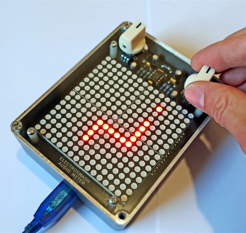
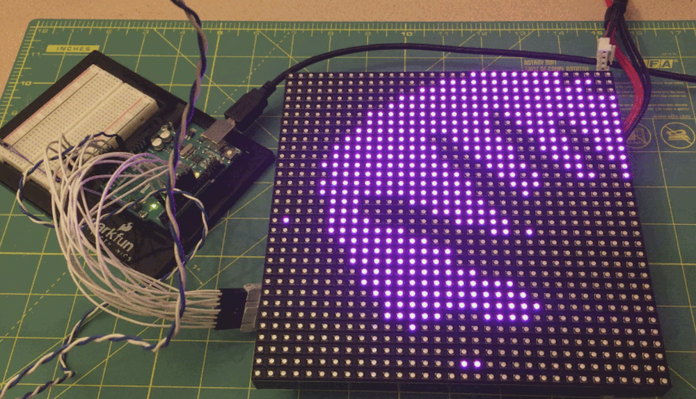
This countdown clock works like you might expect — every day that isn’t your cakeday, a message scrolls by with the number of days remaining until your next one. When the big day comes, the message becomes TODAY IS YOUR CAKE DAY. Both messages are bookended by cute little pixelated cake slices that we would apply liberally to the day-of message if we made one of these.

This simple but fun project shouldn’t put too big of a dent in your parts box, since it’s essentially an Arduino, a real-time clock module, and a 32×8 LED matrix to display the text. We love the uni-body design of the enclosure because it creates a shelf for the Arduino and gives easy access for gluing in the display from the rear. If for some reason you don’t reddit, then make one anyway and use it to count down to your IRL birthday or something. We’ve got the build video cut and plated for you to consume after the break.

We would understand if 2020 is supplying you with enough existential crises, but if not, consider building a clock that counts down the rest of your life expectancy.

Via r/duino

Despite all the incredible advancements made in video game technology over the last few decades, the 8-bit classics never seem to go out of style. Even if you weren’t old enough to experience these games when they were new, it’s impossible not to be impressed by what the early video game pioneers were able to do with such meager hardware. They’re a reminder of what can be accomplished with dedication and technical mastery.

The grid has been split up for easier printing.

If you’d like to put a little retro inspiration on your desk, take a look at this fantastic 16 x 16 LED matrix put together by [Josh Gerdes]. While it’s obviously not the only thing you could use it for, the display certainly seems particularly adept at showing old school video game sprites in all their pixelated glory. There’s something about the internal 3D printed grid that gives the sprites a three dimensional look, while the diffused glow reminds us of nights spent hunched over a flickering CRT.

The best part might be how easy it is to put one of these together for yourself. You’ve probably got most of what you need in the parts bin; essentially it’s just a WS2812B strip long enough to liberate 256 LEDs from and a microcontroller to drive them. [Josh] used an Arduino Nano, but anything compatible with the FastLED library would be a drop-in replacement. You’ll also need a 3D printer to run off the grid, and something to put the whole thing into. The 12×12 shadowbox used here looks great, but we imagine clever folks such as yourselves could make do with whatever might be laying around if you can’t nip off to the arts and crafts store right now.

Beyond looking great, this project is a fantastic reminder of how incredibly handy WS2812 LEDs really are. Whether you’re recreating iconic game sprites or fashioning your own light-up sunglasses, it’s hard to imagine how we managed before these little wonders hit the scene.

[Sofia] spent a lot of time looking around for the perfect LEGO clock. Eventually, she realized that the perfect LEGO clock is, of course, the one you build yourself. So if you find yourself staring at the same old boring clock, contemplating time and the meaning of time itself, why not spend some time making a new timepiece?

You probably already had the LEGO out (no judgment here). This build doesn’t take a whole lot of building blocks — just a microcontroller, a real-time clock module, some LED matrices to display the digits, shift registers if they’re not already built into the matrices, and a pair of buttons for control. [Sofia] used an Arduino Nano, but any microcontroller with enough I/O ought to work. Everybody needs a colorful new way to block out their time.

We love the way this clock looks, especially the transparent panels in front of the LED panels. Given the countless custom pieces out there from all the special sets over the years, we bet you could come up with some really interesting builds.

If your kid is too young to tell time, try building a kid-friendly clock to give them segmented structure.

Via r/duino

[Peterthinks] admits he’s no cabinet maker, so his projects use a lot of hot glue. He also admits he’s no video editor. However, his latest video uses some a MAX7219 to create a 600 character scrolling LED sign. You can see a video of the thing, below. Spoiler alert: not all characters are visible at once.

The heart of the project is a MAX7219 4-in-1 LED display that costs well under $10. The board has four LED arrays resulting in a display of 8×32 LEDs. The MAX7219 takes a 16-bit data word over a 10 MHz serial bus, so programming is pretty easy.

The MAX chip can decode for seven-segment displays or just allow you to light up the outputs directly, which is what the code here does. You can cascade the chips, so it is possible to string more than one of these modules together.

The code is available on Dropbox. The code is extremely simple due to the use of the Parola library and a MAX72XX library. We’ve seen a number of projects based around this chip. Some of the uses are pretty novel.

It’s a well-known fact in capitalist societies that any product or service, if being used in a wedding, instantly triples in cost. Wanting to avoid shelling out big money for a simple photo booth for a friend’s big day, [Lewis] decided to build his own.

Wanting a quality photo output, a Canon DSLR was selected to perform photographic duties. An Arduino Nano is then pressed into service to run the show. It’s hooked up to a MAX7219 LED matrix which feeds instructions to the willing participants, who activate the system with a giant glowing arcade button. When pressed, the Nano waits ten seconds and triggers the camera shutter, doing so three times. Images are displayed on a screen hooked up to the camera’s USB port.

It’s a build that keeps things simple. No single-board PCs needed, just a camera, an Arduino, and a monitor for the display. We’re sure the wedding-goers had a great time, and we look forward to seeing what [Lewis] comes up with next. We’ve seen a few of his hacks around here before, too.

Over the summer [ElectroSmash] put the finishing touches on the Arduino Audio Meter, a shield for the Arduino Uno that visualizes various aspects of an incoming audio signal on a set of four 8×8 LED dot matrices. Obsentisibly it’s for use on a guitar pedalboard, but thanks to the incredible documentation and collection of example code provided by the team, the project promises to be an excellent platform for all sorts of audio experimentation.

Incoming audio is amplified with an MCP6002 and fed into the Uno’s Analog to Digital Converter, where it’s processed via whatever Sketch the user has uploaded. User input is provided by a digital encoder with push-button. A set of four MAX7219 chips control the entire 256-pixel matrix with just three pins on the Arduino. The resolution of the display allows the Arduino Audio Meter to show more than just a simple VU meter, it can even do text and basic graphics.

[ElectroSmash] provides various Sketches for use with the Arduino Audio Meter that provide the expected repertoire of audio visualizations, but they also provide a number of interesting Sketches to expand the capabilities of the device in unexpected ways. Some of them could be useful for a stage musician, such a tool to tune your guitar, whereas others are fun uses of the hardware such as a game of “Snake”.

With the entire project released as open source, users are free to run wild with the Arduino Audio Meter. Writing your own custom software is an obvious first step to making the project your own, but adding additional hardware features and functions certainly aren’t out of the question either.

Our very own [Lewin Day] once walked us through the effort involved in building boutique guitar pedals, and while the Audio Audio Meter’s capabilities are somewhat limited as it doesn’t have the ability to change the audio going through it, we’re still interested in seeing what the community will come up with once they have an easy way to bring their ideas to life.

If you’d like to integrate touch functionality to your LED matrix project, then tuenhidiy may have just the thing for you

The setup uses 16 pairs of IR emitter and receivers arranged down the length of the bi-color 16×32 matrix to tell when one has inserted a finger or other object into an area. When sensed, it changes the corresponding column on the display from red to green or back again.

An Arduino Mega is used for overall control of the device, along with shift registers and multiplexers/demultiplexers to account for the massive amount of IO needed. 

Code for the build is available on GitHub, and you can see it demonstrated in the video below.

Consider that a digital camera uses an array of sensors to capture light from an object. Maker Marcio T, however, decided to turn this idea on its head and instead utilize an array of lights that are detected by a single sensor.

The way it works is that as each LED in a 32×32 matrix illuminates, a phototransistor picks up light if the path is clear or sees no change if the path is blocked. So when you put an object on the matrix, the sensor is able to get an accurate picture of it, enabling its Arduino Uno controller to then generate its silhouette. 

It’s a simple yet very clever hack, and if you pay close attention in the video below, you can see the lights scanning from the bottom to top before the image is produced.

Ordinary digital cameras work by using a large array of light sensors to capture light as it is reflected from an object. In this experiment, I wanted to see whether I could build a backwards camera: instead of having an array of light sensors, I have just a single sensor; but I control each of 1,024 individual light sources in a 32 x 32 LED matrix.

The way it works is that the Arduino illuminates one LED at a time, while using the analog input to monitor changes in the light sensor. This allows the Arduino to test whether the sensor can “see” a particular LED. This process is repeated for each of the 1,024 individual LEDs rapidly to generate a map of visible pixels.

If an object is placed between the LED matrix and the sensor, the Arduino is able to capture the silhouette of that object, which is lit up as a “shadow” once the capture is complete.

Glue sticks are great for attaching electronics and other bits to projects, but as Jon Bumstead shows in his latest work, they can also make pretty cool light diffusers. 

His project takes the form of a wooden box with plexiglass panels, allowing observers to see 64 vertical illuminated glue sticks inside. Hidden within the cube are 128 WS2811 LED modules, melted into the top and bottom of each stick. 

Everything is built around an Arduino Nano, using only a pair of its outputs to control each LED. User interface is provided by a button and knob to adjust speed, color, and patterns.

In this project, I created a “fiber optic” LED matrix using WS2801 LED strip and glue sticks. The light displays have a different look than similar LED cubes and a few advantages. First, you can’t see the actual LEDs in the display because the glue sticks guide the light away from the LEDs. Second, the device requires much fewer LEDs to make up the volume. Because the top and bottom have different LED strips, the fiber optic cables can take on two different colors that mix in the center. There are tons of different color displays that can be achieved with the device. I also added a button and knob for controlling the speed, color, and type of light display.

We remember going to grandfather’s garage. There he would be, his tobacco pipe clenched between his teeth, wisps of smoke trailing into the air around him as he focused, bent over another of his creations. Inside of a simple glass bottle was something impossible. Carefully, ever so carefully, he would use his custom tools to twist wire. He would carefully place each lead. Eventually when the time was right he would solder. Finally he’d place it on the shelf next to the others, an LED matrix in a bottle.

led-message-in-a-bottle-assemblyWell, maybe not, but [Mariko Kosaka]’s father [Kimio Kosaka] has done it. In order to build the matrix, he needed tools that could reach inside the mouth of the bottle without taking up too much space to allow for precise movement. To do this he bent, brazed, twisted, and filed piano wire into tools that are quite beautiful by themselves. These were used to carefully bend and position the LEDs, wires, and other components inside the bottle.

Once the part was ready, he used a modified Hakko soldering iron to do the final combination. We wonder if he even had to be careful to solder quickly so as not to build up a residue on the inside of the bottle? The electronics are all contained inside the bottle. One of the bottles contained another impressive creation of his: an entire Arduino with only wire, dubbed the Arduino Skeleton. Batteries are attached to the cork so when the power runs low it can be removed and replaced without disturbing the creation.

It’s a ridiculous labor of love, and naturally, we love it. There’s a video of it in operation as well as one with him showing how it was done which is visible after the break. He showed them off at the Tokyo Maker Faire where they were surely a hit.


Filed under: Arduino Hacks, led hacks


  • Newsletter

    Sign up for the PlanetArduino Newsletter, which delivers the most popular articles via e-mail to your inbox every week. Just fill in the information below and submit.

  • Like Us on Facebook