
30
Electronic components – the Resistor
education, Electronics, learning electronics, potentiometer, resistor, trimpot, tronixstuff Comments Off on Electronic components – the Resistor
Hello readers
Today we continue with the series of articles on basic electronics with this introductory article about the resistor.
With regards to this article, it is only concerned with direct current (DC) circuits.
What is a resistor? It is a component that can resist or limit the flow of current. Apart from resistors, other electronic components also exhibit an amount of resistance, however the precise amount can vary. The unit of measure of resistance is the Ohm (Ω), and named after the clever German physicist Georg Simon Ohm. He discovered that there was a relationship between voltage (the amount force that would drive a current between two points), current (the rate of flow of an electric charge) and resistance (the measure of opposition to a current) – what we know as Ohm’s law – which states that the current between two points in a conductor is directly proportional to the potential difference (voltage) between the two points, and inversely proportional to the resistance between them.
Or, current = voltage / resistance. You should remember that formula, it can be useful now and again.
But I digress.
There are many types of resistors, each with a different application – but all with the same purpose. Let’s have a look at some now…
Fixed-value leaded resistors
These are the most common type that you will come across. The larger they are, the great amount of watts (the amount of power dissipated by the resistance) they can handle. More common varieties can vary from 0.125 watt to 5 watts. For example, here is a 0.125W resistor, the length of the body is 3.25 mm.:

The body colour of these smaller resistors usually indicates the type of resistor. For example, those with a beige body are carbon resistors. They are usually the cheapest, and have a tolerance of 5%. This means that the indicated value can vary 5% either way – so if your resistor read 100 ohms, the actual value could be between 95 and 105 ohms. Resistors with a blue-ish body are metal-film resistors. They are usually a little bit more expensive, but have a 1% tolerance. Unless you are really trying to save a few cents, use metal-films. Another example is this one watt resistor:

They are much larger, this example is 25mm long and 8mm in thickness. The size of a resistor is generally proportional to its power handling ability.
Do you see the coloured bands around the resistor? They are colour codes, a way of indicating the resistance and tolerance values. And for colour-challenged electronics enthusiasts, a royal PITA. Resistor values can vary, from zero ohms (technically not a resistor… but they do exist for a good reason***) up to thousands of millions (giga-) of ohms.
Let’s learn how to read the resistor colour codes. First of all, have a look at this chart (click to enlarge):

Some resistors will have four bands, some will have five. From personal experience, new resistors are generally five band now. So you just match up the first three bands from left to right, then the fourth band is your multiplier, and the last band is the tolerance. For example, the three resistors below are labelled as 560 ohm resistors:

So the bands are: green, blue, black, black, tolerance – 5, 6, 0 = 560, then 1 for multipler = 560 ohms. The carbon-film resistor (top) has a gold tolerance band – 5%, the others being metal film are brown for 1%. This is why it is much easier to have a nice auto-ranging multimeter.
Now if you need a resistor that can handle more than one watt, you move into ceramic territory. Thankfully these are large enough to have their values printed on them. For example:

There are literally scores of varieties of resistors in this physical category. If you don’t have the time or penchant to visit an electronics store, browse around online catalogues with images such as Digikey, Farnell/Newark (USA), Mouser, etc.
Surface-mount resistors
These are the becoming the norm as technology marches on. Even electronics hobbyists are starting to work with them. They consist of two metal ends which make contact with the circuit board, and a middle section which determines the resistance. They are tiny! The smallest being 0.6 x 0.3 mm in size. The smaller sizes may not have markings, so you need to carefully keep track of them.

As an aside, here is a interesting article on how to solder SMD parts at home. Moving on…
Resistor Arrays
You may find yourself in the situation where you need multiple values of the same resistor in a row, for example to limit current to a bank of LEDs or an LED display module. This is where a resistor array can be convenient. You can usually find arrays with between four and sixteen resistors in a variety of casings which speeds up prototyping greatly – however they do cost more than the individual resistors. For example: (hover over image for description)


Variable resistors
As expected there are many types of variable resistors, from the tiny to the large. Just like fixed-value resistors you need to ensure the power-handling (watts value) is sufficient for your project.
Variable resistors normally consist of a surface track that has resistive properties, and a tiny arm or contact that moves along the track. There are three terminals, one at each end of the track, and one to the arm or wiper. You would normally use the wiper contact and one of the others, depending on which way you want the variable resistor to operate (either increasing or decreasing in resistance). For example:

So as the wiper moves clockwise, the resistance increases…
Starting with the small – a variety of trimpots, used more for refining settings and not general everyday user input. Here is a small range of PCB-mount trimpots:

The two on the left are not sealed, exposed to dust and other impurities that can interfere with them. The two on the right are enclosed, and have a smoother feel when adjusting, and are generally preferable. These trimpots are single-turn, which can make getting finite adjustments in high-value resistances rather difficult. However you can purchase multi-turn trimpots allowing you greater detail in adjustment. Trimpots are usually labelled very well, depending on the manufacturer. For example, the black one above is 10k ohm, easy. Some will have a numerically coded version. Such as the one on the right. It is labelled 501, which means 50 ohms with 1 zero after it, so it is 500 ohms. Another example is 254, that is 25 with four zeros, i.e. 250000 ohms or 25 kilo ohm.
Next up are potentiometers – the garden variety variable resistor.

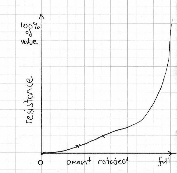
Apart form the resistance and wattage value, there are two major types to choose from: linear and logarithmic. The resistance of linear ‘pots’ is equally proportional to the angle of adjustment. That is, if you turn it half-way, its value is (around) 50% of the total resistance. Ideal for adjusting voltage, brightness, etc. Logarithmic are usually for volume controls. Here is a very crude example of the logarithmic VR’s resistance value relative to wiper position:
 When identifying your variable resistor, units marked with ‘A’ next to the value are logarithmic, and ‘B’ are linear. For example, B10k is a 10 kilo ohm linear potentiometer. These types are also available as doubles, so you can adjust two resistances at the same time – ideal for stereo volume controls. If you are going to build a project with these and mount them into a case, be sure to check that the knobs you want to use match the shaft diameter of the potentiometer before you finalise your design.
Light-dependent resistors
These can be a lot of fun. In total darkness their resistance value is quite high, around 1 mega ohm, but in normal light drops to around 17 kilo ohm (check your data sheet). They are quite small, the head being around 8mm in diameter.

Great for determing day or night time, logging sunrise and sunset durations, or making something that buzzes only in the dark like a cricket.
Digital potentiometers
Imagine a tiny integrated circuit that contained hundreds of resistors in series, and could have the resistance selected by serial digital control. These are usually classified by the total resistance, the number of potentiometers in the chip, the number of divisions of the total resistance offered, and the volatility of the wiper. That is, when the power is turned off, does it remember where the wiper was upon reboot, or reset to a default position. For example, Maxim IC have a range of these here.
Thermistors
Think of a thermistor as a resistor that changes its resistance relative to the ambient temperature. Here is a thermistor as found in the Electronic Bricks:

And the circuit symbol:

There are positive and negative thermistors, which increase or decrease their resistance relative to the temperature. Within the scope of this website, thermistors are not an idea solution to measure temperature with our microcontrollers, it is easier to use something like an Analog Devices TMP36. However, in general analogue situations thermistors are used widely.
Mathematics of resistors
Working with resistors is easy, however some planning is required. One of the most popular uses is to reduce current to protect another component. For example, an LED. Say you have an LED that has a forward voltage of 2 volts, draws 20 mA of current, and you have a 5V supply. What resistor value will you use?

First of all, note down what we know: Vs (supply voltage) = 5V, Vl (LED voltage) = 2V, Il (LED current = 0.02A). Using Ohm’s law (voltage = current x resistance) we can rearrange it so:
resistance = voltage / current
So, resistance = (5-2)/0.02 = 150 ohms.
So in the circuit above, R1 would be 150 ohms
Resistors in series

If you have resistors in series, the total resistance is just the sum of the individual values. So R = R1 + R2 + R3 …Rx
Resistors in parallel
Using resistors in parallel is a little trickier. You might do this to share the power across several resistors, or to make a value that you can’t have with a single resistor.


Voltage division with resistors
If you cannot reduce your voltage with a zener diode, another method is voltage division with resistors. Simple, yet effective.

Always check that the resistors you are using are of a suitable power handling type. Remember that W = V x A (power in watts = volts x current in amps)!
Well that wraps up my introduction to resistors. As always, thank you for reading and I look forward to your comments and so on. Please subscribe using one of the methods at the top-right of this web page to receive updates on new posts. Or join our new Google Group.
Otherwise, have fun and make something!
![]()
Some information for this post is from: historical info from Wikipedia; various technical information from books by Forrest Mims III, “Electronics Demystified” by Stan Gibilisco; ceramic, array, LDR and SMD resistor photos from Farnell Australia. *** Email me with your interpretation of why zero-ohm resistors exist and enter the draw for a random prize from my component stock! Answers must be in by 14th June 2010, 1200h Australian EST.


