The Whiskey Tango Hotel blog looks to simulate the lights of fireworks with a single long strip of NeoPixels, aka WS2812B addressable LEDs.
Fireworks are also pretty cool. On the downside they can be dangerous, scare wildlife, start fires, be expensive, illegal, etc. So, until we can afford our own fleet of drones we settled on this alternative.
The hardware is an ESP8266 and a WS2812B LED-strip with 300 LEDs (16.5 feet). We wanted to use a Arduino Nano (because we had one), but due to the amount of memory needed to define the arrays for the 300 LEDs we went with an ESP8266 (because we had one).
See the video below and the post with Arduino source code.
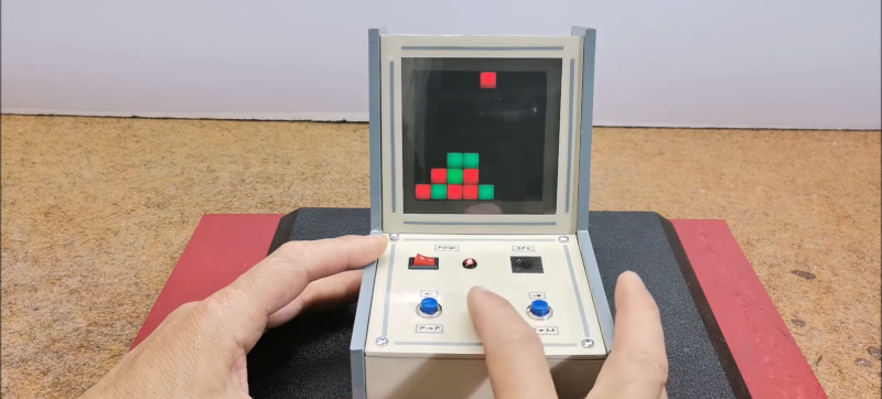
You might think that making your own electronic games would require some kind of LCD, but lately, [Mirko Pavleski] has been making his using inexpensive 8X8 WS2812B LED panels. This lets even a modest microcontroller easily control a 64-pixel “screen.” In this case, [Mirko] uses an Arduino Nano, 3 switches, and a buzzer along with some 3D printed components to make a good-looking game. You can see it in action in the video below.
The WS2812B panels are easy to use since the devices have a simple protocol where you only talk to the first LED. You send pulses to determine each LED’s color. The first LED changes color and then starts repeating what you send to the next LED, which, of course, does the same thing. When you pause a bit, the array decides you are done, and the next train of pulses will start back at the first LED.
It looks like the project is based on a German project from [Bernd Albrecht], but our German isn’t up to snuff, and machine translation always leaves something to be desired. Another developer added a play against the computer mode. This is a simple program and would be easy to port to the microcontroller of your choice. [Mirko]’s execution of it looks like it could be a commercial product. If you made one as a gift, we bet no one would guess you built it yourself.
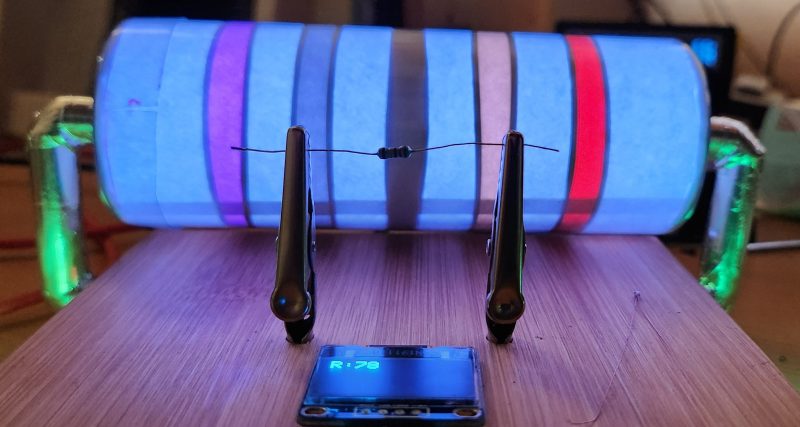
With surface-mount components quickly becoming the norm, even for homebrew hardware, the resistor color-code can sometimes feel a bit old-hat. However, anybody who has ever tried to identify a random through-hole resistor from a pile of assorted values will know that it’s still a handy skill to have up your sleeve. With this in mind, [j] decided to super-size the color-code with “The Great Resistor”.
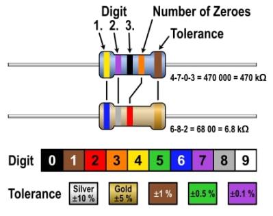
How the resistor color-code bands work
At the heart of the project is an Arduino Nano clone and a potential divider that measures the resistance of the test resistor against a known fixed value. Using the 16-bit ADC, the range of measurable values is theoretically 0 Ω to 15 MΩ, but there are some remaining issues with electrical noise that currently limit the practical range to between 100 Ω and 2 MΩ.
[j] is measuring the supply voltage to help counteract the noise, but intends to move to an oversampling/averaging method to improve the results in the next iteration.
The measured value is shown on the OLED display at the front, and in resistor color-code on an enormous symbolic resistor lit by WS2812 RGB LEDs behind.
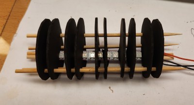
Inside The Great Resistor, the LEDs and baffle plates make the magic work
Precision aside, the project looks very impressive and we like the way the giant resistor has been constructed. It would look great at a science show or a demonstration. We’re sure that the noise issues can be ironed out, and we’d encourage any readers with experience in this area to offer [j] some tips in the comments below. There’s a video after the break of The Great Resistor being put through its paces!
With surface-mount components quickly becoming the norm, even for homebrew hardware, the resistor color-code can sometimes feel a bit old-hat. However, anybody who has ever tried to identify a random through-hole resistor from a pile of assorted values will know that it’s still a handy skill to have up your sleeve. With this in mind, [j] decided to super-size the color-code with “The Great Resistor”.
How the resistor color-code bands work
At the heart of the project is an Arduino Nano clone and a potential divider that measures the resistance of the test resistor against a known fixed value. Using the 16-bit ADC, the range of measurable values is theoretically 0 Ω to 15 MΩ, but there are some remaining issues with electrical noise that currently limit the practical range to between 100 Ω and 2 MΩ.
[j] is measuring the supply voltage to help counteract the noise, but intends to move to an oversampling/averaging method to improve the results in the next iteration.
The measured value is shown on the OLED display at the front, and in resistor color-code on an enormous symbolic resistor lit by WS2812 RGB LEDs behind.
Inside The Great Resistor, the LEDs and baffle plates make the magic work
Precision aside, the project looks very impressive and we like the way the giant resistor has been constructed. It would look great at a science show or a demonstration. We’re sure that the noise issues can be ironed out, and we’d encourage any readers with experience in this area to offer [j] some tips in the comments below. There’s a video after the break of The Great Resistor being put through its paces!
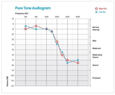
Hearing loss is a common problem for many – especially those who may have attended too many loud concerts in their youth. [mircemk] had recently been for a hearing test, and noticed that the procedure was actually quite straightforward. Armed with this knowledge, he decided to build his own test system and document it for others to use.
Resultant audiogram from the device showing each ear in a different color
By using an Arduino to produce tones of various stepped frequencies, and gradually increasing the volume until the test subject can detect the tone, it is possible to plot an audiogram of hearing threshold sensitivity. Testing each ear individually allows a comparison between one side and the other.
[mircemk] has built a nice miniature cabinet that holds an 8×8 matrix of WS2812 addressable RGB LEDs. A 128×64 pixel OLED display provides user instructions, and a rotary encoder with push-button serves as the user input.
Of course, this is not a calibrated professional piece of test equipment, and a lot will depend on the quality of the earpiece used. However, as a way to check for gross hearing issues, and as an interesting experiment, it holds a lot of promise.
There is even an extension, including a Class D audio amplifier, that allows the use of bone-conduction earpieces to help narrow down the cause of hearing loss further.
Like pretty much all of us, [Andy Schwarz] loves RGB LEDs. Specifically he likes to put them on RC vehicles, such as navigation lights on airplanes or flashers and headlights on cars. He found himself often rewriting very similar Arduino code for each one of these installations, and eventually decided he could save himself (and all the other hackers in the world) some time by creating a customizable Arduino firmware specifically for driving RGB LEDs.
The software side of this project, which he’s calling BitsyLED, actually comes in two parts. The first is the firmware itself, which is designed to control common RGB LEDs such as the WS2812 or members of the NeoPixel family. It can run on an Arduino Pro Mini with no problems, but [Andy] has also designed his own open hardware control board based on the ATtiny84 that you can build yourself. Currently you need a USBASP to program it, but he’s working on a second version which will add USB support.
With your controller of choice running the BitsyLED firmware, you need something to configure it. For that, [Andy] has developed a Chrome extension which offers a very slick user interface for setting up colors and patterns. The tool even allows you to create a visual representation of your LEDs so you can get an idea of what it’s going to look like when all the hardware is powered up.
Light painting is a technique which allows you to “draw” on a photograph by moving a light past the camera during a long exposure shot. While it can be difficult to master, light painting allows for some incredible effects such as text and images that appear to be hovering in mid-air. Think of it like a very slow but much cooler version of an augmented reality app.
[Reven] recently wrote in to tell us about the Arduino light painter he put together, and while DIY (and even commercial) light painting gear isn’t exactly new at this point, we think he’s raised the bar a bit with his design. With the addition of a slick 3D printed enclosure and on-board display and menu system, his light painter looks exceptionally professional for being built out of hardware he had on hand.
On his blog, [Reven] has done a phenomenal job of documenting the build from start to finish. Not only does he include a detailed Bill of Materials and the STL files so you can build your own version of his light painter, he walks the reader though his design process and explains why he did the things he did. Even if you aren’t interested in building a light painter, there’s almost certainly something of interest for anyone who’s ever looked at a pile of parts on their workbench and wondered how they were going to turn it into a functioning device.
Powered by an Arduino Uno, the light painter provides a user interface on a 16×2 LCD which allows control over not only the brightness of the WS2812 LED strips but selecting and loading different images from the micro SD card. The case was designed in FreeCAD, and while [Reven] mentions there are a number of issues which could be improved, satisfies all his design goals.
If you have OCD, then the worst thing someone could do is give you a bowl of multi-coloured M&M’s or Skittles — or Gems if you’re in the part of the world where this was written. The candies just won’t taste good until you’ve managed to sort them in to separate coloured heaps. And if you’re a hacker, you’ll obviously build a sorting machine to do the job for you.
Use our search box and you’ll find a long list of coverage describing all manner and kinds of sorting machines. And while all of them do their designated job, 19 year old [Willem Pennings]’s m&m and Skittle Sorting Machine is the bees knees. It’s one of the best builds we’ve seen to date, looking more like a Scandinavian Appliance than a DIY hack. He’s ratcheted up a 100k views on Youtube, 900k views on imgur and almost 2.5k comments on reddit, all within a day of posting the build details on his blog.
As quite often happens, his work is based on an earlier design, but he ends up adding lots of improvements to his version. It’s got a hopper at the top for loading either m&m’s or Skittles and six bowls at the bottom to receive the color sorted candies. The user interface is just two buttons — one to select between the two candy types and another to start the sorting. The hardware is all 3D printed and laser cut. But he’s put in extra effort to clean the laser cut pieces and paint them white to give it that neat, appliance look. The white, 3D printed parts add to the appeal.
Rotating the input funnel to prevent the candies from clogging the feed pipes is an ace idea. A WS2812 LED is placed above each bowl, lighting up the bowl where the next candy will be ejected and at the same time, a WS2812 strip around the periphery of the main body lights up with the color of the detected candy, making it a treat, literally, to watch this thing in action. His blog post has more details about the build, and the video after the break shows the awesome machine in action.
The WS2812 is an amazing piece of technology. 30 years ago, high brightness LEDs didn’t even exist yet. Now, you can score RGB LEDs that even take all the hard work out of controlling and addressing them! But as ever, we can do better.
Riffing on the ever popular Adafruit NeoPixel library, [Harm] created the WS2812FX library. The library has a whole laundry list of effects to run on your blinkenlights – from the exciting Hyper Sparkle to the calming Breathe inspired by Apple devices. The fantastic thing about this library is that it can greatly shorten development time of your garden-variety blinkables – hook up your WS2812s, pick your effect, and you’re done.
[Harm]’s gone and done the hard yards, porting this to a bevy of platforms – testing it on the Arduino Nano, Uno, Micro and ESP8266. As a proof of concept, they’ve also put together a great demonstration of the software – building some cute and stylish Christmas decorations from wood, aluminium, and hacked up Christmas light housings. Combining it with an ESP8266 & an app, the effects can be controlled from a smartphone over WiFi. The assembly video on YouTube shows the build process, using screws and nails to create an attractive frame using aluminium sheet.
This project is a great example of how libraries and modern hardware allow us to stand on the shoulders of giants. It’s quicker than ever to build amazingly capable projects with more LEDs than ever. Over the years we’ve seen plenty great WS2812 projects, like this sunrise alarm clock or this portable rave staff.
As always, blink hard, or go home. Video after the break.
The most fascinating project you can build is something with a bunch of blinky hypnotic LEDs, and the easiest way to build this is with a bunch of individually addressable RGB LEDs. [Ole] has a great introduction to driving RGB LED matrices using only five data pins on a microcontroller.
The one thing that is most often forgotten in a project involving gigantic matrices of RGB LEDs is how to mount them. The enclosure for these LEDs should probably be light and non-conductive. If you’re really clever, each individual LED should be in a light-proof box with a translucent cover on it. [Ole] isn’t doing that here; this matrix is just a bit of wood with some WS2812s glued down to it.
To drive the LEDs, [Ole] is using an Arduino. Even though the WS2812s are individually addressable and only one data pin is needed, [Ole] is using five individual data lines for this matrix. It works okay, and the entire setup can be changed at some point in the future. It’s still a great introduction to individually addressable LED matrices.
If you’d like to see what can be done with a whole bunch of individually addressable LEDs, here’s the FLED that will probably be at our LA meetup in two weeks. There are some crazy engineering challenges and several pounds of solder in the FLED. For the writeup on that, here you go.
Planet Arduino is, or at the moment is wishing to become, an aggregation of public weblogs from around the world written by people who develop, play, think on Arduino platform and his son. The opinions expressed in those weblogs and hence this aggregation are those of the original authors. Entries on this page are owned by their authors. We do not edit, endorse or vouch for the contents of individual posts. For more information about Arduino please visit www.arduino.cc
You are currently browsing the archives for the ws2812 category.