In retrocomputing circles, it’s often the case that the weirder and rarer the machine, the more likely it is to attract attention. And machines don’t get much weirder than the DEC Rainbow 100-B, sporting as it does both Z80 and 8088 microprocessors and usable as either a VT100 terminal or as a PC with either CP/M or MS-DOS. But hey — at least it got the plain beige box look right.
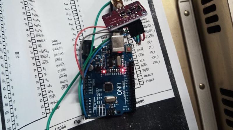
Weird or not, all computers have at least a few things in common, a fact which helped [Dr. Joshua Reichard] home in on the problem with a Rainbow that was dead on arrival. After a full recapping — a prudent move given the four decades since the machine was manufactured — the machine failed to show any signs of life. The usual low-hanging diagnostic fruit didn’t provide much help, as both the Z80 and 8088 CPUs seemed to be fine. It was then that [Joshua] decided to look at the heartbeat of the machine — the 24-ish MHz clock shared between the two processors — and found that it was flatlined.
Unwilling to wait for a replacement, [Joshua] cobbled together a temporary clock from an Arduino Uno and an Si5351 clock generator. He connected the output of the card to the main board, whipped up a little code to generate the right frequency, and the nearly departed machine sprang back to life. [Dr. Reichard] characterizes this as a “defibrillation” of the Rainbow, and while one hates to argue with a doctor — OK, that’s a lie; we push back on doctors all the time — we’d say the closer medical analogy is that of fitting a temporary pacemaker while waiting for a suitable donor for a transplant.
This is the second recent appearance of the Rainbow on these pages — [David] over at Usagi Electric has been working on the graphics on his Rainbow lately.
A traditional early project for someone discovering a love for electronics has been for many years a metal detector. This would mean a few transistors back in the day, but today it’s more likely to involve a microcontroller. [Mircemk] has an example that bends both worlds, with a single transistor oscillator and an Arduino.
This type of metal detector has a large search coil which forms part of the tuned circuit in an oscillator. As a piece of metal enters its range the frequency of oscillation changes. In the old days, this would have been detected as an audible beat frequency with another oscillator. This design would require a calibration step at the start of detecting, to tune the two oscillators to the same frequency.
This detector keeps the first oscillator but eschews the second one in favor of an Arduino. The microcontroller acts as a frequency counter, monitoring the frequency and issuing an alarm when it detects a change likely to be caused by a piece of metal. It may not have some of the finess a human ear could apply to a beat frequency in the all-analogue days, but it’s simple enough to build and it avoids the need for calibration. Seeing it in the video below the break we’re sure that just like those transistor models old, there will be plenty of fun to be had with it.
When you show up at a party wearing this bare PCB watch, there are effectively two possible reactions you might receive from the other people there. Either they are going to snicker at the nerd who’s wearing a blinking circuit board on their wrist in public, or they are going to marvel at the ridiculously low part count. We’ll give you one guess as to which reaction you’d likely get at any event Hackaday is involved in.
You’re probably wondering how [Electronoobs] pulled this off without an external clock source for the ATmega328P chip. The chip actually has an internal 8 MHz oscillator that can be used, but you need to flash the appropriate bootloader to it first. Accordingly, the backside of the PCB has both SPI and a UART solder pads for external bootloader and firmware programming.
As you might expect, there’s a downside to using the internal oscillator: it’s not very good. The ATmega328P spec sheet claims a factory calibrated accuracy of ±10%, and [Electronoobs] has found that equates to a clock drift of around 15 seconds per day. Not exactly great, but considering the battery only lasts for two days anyway, it doesn’t have much of an impact in this case.
So what’s the Arduino in there for? This is a digital Theremin, but check out the video below and you’ll agree that it sounds amazing and has excellent response. The aluminum antennas used for volume and pitch are attached to the top portion of the shield but it sounds like they’re not included in the kit. Don’t fret, you can use a variety of materials for this purpose. On the bottom you need to connect a speaker cable, and also a ground wire if that cable’s not grounded.
As the name implies, this is Open Hardware and we’re quite happy with the documentation on their site and the BOM (found on the GitHub repo). This design was shown off back in 2013 hiding in a pack of cigarettes. If you don’t want to build your own they’re selling kits on their site for 48 Euro delivered, or on Tindie for $55.
Okay, we’ve screwed this up so many times that we’re going to try to get it right here: the Theremin was not heard in the opening of Star Trek the original series, or in the opening of Doctor Who. It wasn’t featured in “Good Vibrations” either. As far as we can tell, it’s not used for anything in pop culture at all… but recognizing the sound and knowing what one is remains core geek knowledge.
Historically when hams built low power (QRP) transmitters, they’d use a crystal to set the frequency. Years ago, it was common to find crystals in all sorts of radios, including scanners and handheld transceivers. Crystals are very stable and precise and it is relatively easy to make a high quality oscillator with a crystal and a few parts.
The big problem is you can’t change the frequency much without changing crystals. Making a high quality variable frequency oscillator (VFO) out of traditional components is quite a challenge. However, today you have many alternatives ranging from digital synthesis to all-in-one IC solutions that can generate stable signals in a wide range of frequencies.
[N2HTT] likes to build radio projects and he decided to take an Si5351 clock generator and turn it into a three frequency VFO for his projects. The Si5351 uses a crystal, so it is very stable. However, you can digitally convert that crystal frequency into multiple frequencies over a range of about 8kHz to 160MHz.
The chip has two PLLs that multiply the crystal frequency by a programmable amount. Then you can set each channel to start with the crystal frequency or either PLL and divide it by an integer or a fractional amount. As you might expect, the integer divisions result in a more stable output, but if you really need a particular frequency and can accept some jitter, you can get almost anything you want out of the device.
One thing of interest is the breadboard the VFO is built on. [N2HTT] used an Arduino and a small display along with an encoder to control the chip. But the chip generates some high frequencies and common wisdom is that solderless breadboards aren’t good for high frequency. Acting on a tip he read in a magazine article [N2HTT] took a bamboo cutting board and then affixed standard solderless breadboards to unetched copper PCB material. He then made sure the PCB ground planes were well connected and grounded. It seems to work (you can see it working in the video below).
The output of the chip is a square wave, so if you wanted to use it for radio applications, you’d probably have to low pass filter the output to get a sine wave. The device is only as accurate as the crystal and will exhibit some phase noise and jitter (especially if you don’t have integer divisions). However, having a wide range programmable frequency source for a few bucks is a great building block for lots of different projects.
In this review we examine the Pocket Oscillator Kit from Altronics, based on an design from (the now defunct) February and March 1989 editions of Electronics Australia magazine. The purpose of this oscillator is to give you a high quality, portable square or sine wave generator that can be used to test audio equipment, speaker response, fool about with oscilloscopes (!), and so on. The prototype basic specifications are as follows:
Frequency range: 41~1082 Hz and 735 Hz~18.1 kHz
Output: 1.27V RMS sine, 1.45V peak square
Load: 1.0V RMS sine into 330 Ω
Distortion: 0.16% THD at 1 kHz
Assembly
The kit is packaged in typical form, without any surprises:
In the usual Altronics fashion, the instructions are accompanied with a neat “electronics reference sheet” which covers many useful topics such as resistor colour codes, various formulae, PCB track widths, pinouts and more. The kit instructions are based on the original magazine article and include a small addendum which isn’t any problem.
Unlike some kits, everything is included to create a finished product (except for the IC socket):
… including a nice enclosure which has the control instructions screen-printed on the lid…
However at this point I think the definition of a “pocket” is the same used by Sir Clive Sinclair when he had those pocket televisions. At this time I won’t use the enclosure as my drill press is in storage, however look forward to fitting the kit within at a later point. The PCB has a neat solder mask and silk screen:
Assembly was pretty straight forward, the original design has tried to minimise PCB real-estate, so all the resistors are mounted vertically. The signal diodes take this a step further – each pair needs to be soldered together:
… then the pair is also mounted vertically:
However it all works in the end. The rest of the circuit went together well, and we used our own IC socket for the opamp:
From this point you need to wire up the power, switches and potentiometers:
… and consider mounting the whole lot in the enclosure (or before assembly!):
However as mentioned earlier, I just went for the open octopus method for time being:
How it works
The oscillator is based around the Texas Instruments TL064 opamp, and due to copyright I can’t give you the schematic. For complete details on the oscillator, either purchase the kit or locate the February and March 1989 edition of Electronics Australia magazine. However the waveforms from the oscillator looked good (as far as they can on a DSO):
Conclusion
The oscillator works well, however the PCB layout could have been a little lot easier on the end-user. It’s time for a redesign, possibly put all the contacts for external switches around the perimeter – and allow space for the diodes to lay normally. Nevertheless – this is a neat kit, and still quite popular after all these years. For the price you get a few hours of kit fun and a useful piece of test equipment. So if you’re into audio or experimenting, check it out. Full-sized images are available on flickr.
And while you’re here – are you interested in Arduino? Check out my new book “Arduino Workshop” from No Starch Press – also shortly available from Altronics.
In the meanwhile have fun and keep checking into tronixstuff.com. Why not follow things on twitter, Google+, subscribe for email updates or RSS using the links on the right-hand column? And join our friendly Google Group – dedicated to the projects and related items on this website. Sign up – it’s free, helpful to each other – and we can all learn something.
[Note - kit purchased without notifying the supplier]
As a beginner in the world of electronics, sooner or later you’ll want to make a more permanent project than what can be constructed on the solderless breadboard. It’s easy to say “make your own PCBs” – however this can introduce a steep learning curve, not to mention the cost and time involved in waiting for PCBs to arrive – and hoping they’re correct. Thus for many people a happy medium is transferring prototype circuits over to stripboard – it’s really cheap (check ebay), you can keep various sizes on hand, and it’s quick.
However planning more complex circuits can be difficult – so it would be much easier with the use of a software design tool. Which brings us to the subject of our review – the Lochmaster v4.0 software from Abacom. It’s an incredibly easy to use developer’s tool for strip board projects. No more loose pieces of graph paper, soldering parts “one row too far over”, or lost design plans – you can now design stripboard projects efficiently and with ease.
Installation
Available for all versions of Windows from XP to 8, Lochmaster is less than ten megabytes and is distributed electronically after purchase – so backup your installation file when received. Otherwise it’s a quick install, you don’t need any extra framework software and due to the size will run well on less-specified machines. Although we have screen shots in the review below, you can download a trial version - so it won’t cost you anything to check it out yourself.
Designing your circuits
Once installed, opening Lochmaster for the first time you’re presented with a blank example of stripboard ready for your components:
However you can also use different types of prototyping board, such as varieties with all holes, edge connectors, mounting holes, different copper directions – or even make your own board to match a preferred style. Boar dimensions can be displayed in measurement units as well as “holes”. Then it’s a simple matter of selecting a part library from the drop-down list on the left of the window. For example, to add a 555 timer (which is an 8-pin DIL part) select the “ICs” library, click on the 8-pin enclosure and the following window appears, prompting you to fill out the appropriate details such as label, type etc:
… then you can drop the 555 on the board. It then becomes an object which can be dragged around and placed where you need it. You can also create and modify the component libraries, and also create your own custom parts.
At that point, you might want to cut the tracks on the other side of the board. By clicking the “turn around” button the menu bar, you’re presented with the bottom of the board. Using the “add/split” button on the vertical toolbar between the library and the board, you can then virtually cut the tracks, for example:
You can also see the rounded circles which represent solder joints. After a few minutes we found dragging and dropping components onto the board very simple, and with the turn-around button you can easily flip sides until the placement looks good. After placing components, running the necessary links or wires is simple with the “draw jumper wire” tool. They can run in any direction, and also have corners, for example:
You can also adjust the colours and thickness of the wires, and of course can also be placed on the other side of the board – just flip it around and place the wires. After wiring things up and getting to the stage when you’re ready to build – you can test the connections to ensure you haven’t mis-counted holes or tracks. Using the “Test mode” tool you can click on tracks and the sections that are electrically connected to the point with the cursor are all highlighted – for example if you click on the point marked by the black arrow below, the connected tracks are highlighted:
If you don’t like the 3D-rendered components, you can also work with normal 2D in colour or black and white:
For final quality-control, you can also review the project at any time with “X-ray” view, which shows an outline of the parts on the other side, for example when looking at the bottom of the board, turning on X-ray results with:
You can also generate component lists, which are great for documentation or simply making up a shopping list. It can be exported to .xls or text file, for example:
And then you can export your project as an image (.jpg or .bmp), HPGL machine file – and print out both sides to serve as an assembly guide. There is also standalone file-viewer software, so you can share your designs with others who haven’t got the full Lochmaster software installed.
Example project
After experimenting with Lochmaster for a short while, we decided to test using it with a real project that a beginner might assemble. For example, a square wave oscillator from an old Talking Electronics magazine (click image for larger version):
Nothing too complex, but a useful tool for anyone experimenting with electronics. It’s a 555 astable with six different RC values which allows you to select from 1, 10, 100, 1 k, 10 k and 100 kHz outputs. The first step is to gather all the components together, so you know the widths and number of holes each needs on the stripboard:
The next step is to measure the board, as you can enter the dimensions via Board>Edit board layout… into Lochmaster to avoid having excess space in the design plan. Then after consulting the schematic and the single-layer PCB layout from the magazine, it’s a simple matter of placing the parts onto the virtual board after checking how the fit in on the real thing:
… and the flip-side:
Not a work of art – but it works. (We didn’t fit the 100 kHz setting, as the capacitor wasn’t in stock). And that’s the neat thing – you can experiment with placement until you’re happy, then double-check connections before soldering. You might find even after some planning, that you may deviate from the plan. Fair enough, but just double-check what you’re doing. And a short while later, the results, top and bottom:
Conclusion
If you’re a beginner and don’t have the time, money and patience to design your own PCBs – Lochmaster is ideal. It’s a neater way to visualise physical circuits, as well as filing and sharing them with others. To order your own copy, get the trial version, or if you have any questions please contact Abacom. Full-sized images of the screen-shots can be found on flickr. And if you made it this far – check out my new book “Arduino Workshop” from No Starch Press.
In the meanwhile have fun and keep checking into tronixstuff.com. Why not follow things on twitter, Google+, subscribe for email updates or RSS using the links on the right-hand column? And join our friendly Google Group – dedicated to the projects and related items on this website. Sign up – it’s free, helpful to each other – and we can all learn something.
[Note - Lochmaster software license was a promotional consideration from Abacom]
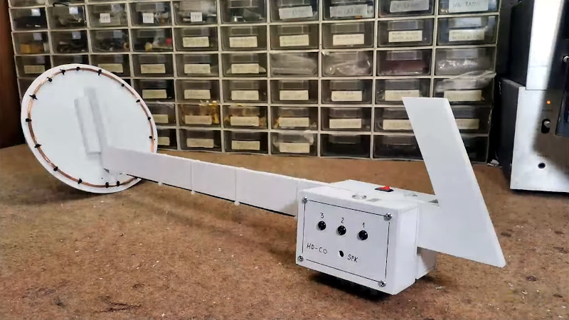
[Dzl] and his rather serious looking son are metal detector enthusiasts. But when they couldn’t find their store-bought metal detector earlier this summer they just went ahead and built their own. [Dzl] starts his write up with an explanation of how most oscillator based metal detectors work. This one differs by using an Arduino to read from the metal detecting coil.
The circuit starts with an oscillator that produces a signal of about 160 kHz which is constantly measured by the Arduino. When metal enters the coil it alters the frequency, which is immediately picked up the Arduino. Instead of that characteristic rising tone this rig uses a Piezo buzzer, issuing the type of clicks you’d normally associate with a Geiger counter.
The last part of the build was to find the best coil orientation. They settled on thirty turns around a metal bucket. An old Ikea lamp is the perfect form factor to host their hardware which seems to work like a charm.
Today we continue down the path of analog electronics theory by stopping by for an introductory look at the RC circuit. That’s R for resistor, and C for capacitor. As we know from previous articles, resistors can resist or limit the flow of current in a circuit, and a capacitor stores electric current for use in the future. And – when used together – these two simple components can be used for many interesting applications such as timing and creating oscillators of various frequencies.
How is this so? Please consider the following simple circuit:
When the switch is in position A, current flows through R1 and into the capacitor C1 until it is fully charged. During this charging process, the voltage across the capacitor will change, starting from zero until fully charged, at which point the voltage will be the same as if the capacitor had been replaced by a break in the circuit – in this case 6V. Fair enough. But how long will the capacitor take to reach this state? Well the time taken is a function of several things – including the value of the resistor (R1) as it limits the flow of current; and the size of the capacitor – which determines how much charge can be stored.
If we know these two values, we can calculate the time constant of the circuit. The time constant is denoted by the character zeta (lower-case Greek Z).
The time constant is the time taken (in seconds) by the capacitor C that is fed from a resistor R to charge to a certain level. The capacitor will charge to 63% of the final voltage in one time constant, 85% in two time constants, and 100% in five time constants. If you graphed the % charge against time constant, the result is exponential. That is:
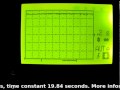
Now enough theory – let’s put this RC circuit to practice to see the voltage change across the capacitor as it charges. The resistor R1 will be 20k ohm, the capacitor 1000 uF.
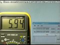
Our time constant will be R x C which will be 20000 ohms x 0.001 farads, which equals 20 (seconds). Notice the unit conversion – you need to go back to ohms and farads not micro-, pico- or nanofarads. So our example will take 20 seconds to reach 63% of final voltage, and 100 seconds to reach almost full voltage. This is assuming the values of the resistor and capacitor are accurate. The capacitor will have to be taken on face value as I can’t measure it with my equipment, and don’t have the data sheet to know the tolerance. The resistor measured at 19.84 k ohms, and the battery measured 6.27 volts. Therefore our real time constant should be around 19.84 seconds, give or take.
First of all, here is a shot of the little oscilloscope measuring the change in voltage over the capacitor with respect to time. The vertical scale is 1v/division:
And here is the multimeter measuring the voltage next to a stopwatch. (crude yet effective, no?)
The two videos were not the most accurate, as it was difficult to synchronise the stopwatch and start the circuit, but I hope you could see the exponential relationship between time and voltage.
What about discharging? Using the circuit above, if we moved the switch to B after charging the capacitor – and R2 was also 20k ohm – how long would it take to discharge the capacitor? Exactly the same as charging it! So one time constant to discharge 63% and so on. So you can take the graph from above and invert it as such:
How can we make use of an RC circuit?
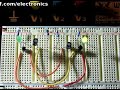
I’m glad you asked. Consider the following circuit:
When power is applied, the capacitor starts to charge, and in doing so allows current to flow to the emitter of the transistor, which turns on the LED. However as the capacitor charges, less current passes to the base of the transistor, eventually turning it off. Therefore you can calculate time constants and experiment to create an off timer. However, a preferable way would be to make use of a 555 timer. For example, an RC combination is used to set the pulse length used in astable timing applications, for example using R1, R2 and C1:
Another use of the RC circuit is oscillating. Due to varying capacitor values due to tolerance, you most likely cannot make precision frequency generators, but you can still have some fun and make useful things. Here is a classic oscillator example – an astable multivibrator:
What is going on here? Here it is in action:
and here is one side being measured on the little scope:
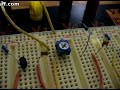
We have two RC circuits, each controlling a transistor. When power is applied, there is no way to determine which side will start first, as this depends on the latent charge in the capacitors and the exact values of the resistors and capacitors. So to start let’s assume the left transistor (Q1) and LED are on; and the right transistor (Q2) and LED are off. The voltage at collector of Q1 will be close to zero as it is on. And the voltage at the base of Q2 will also be close to zero as C2 will initially be discharged. But C2 will now start charging via R4 and base of Q1 to around 5.4V (remember the 0.6v loss over the base-emitter junction of a transistor). While this is happening, C1 starts charging through R2. Once the voltage difference reaches 0.6V over the capacitor, Q2 is turned on.
But when Q2 is on, the voltage at the collector drops to zero, and C2 is charged, so it pulls the voltage at the base of Q1 to -5.4v, turning it off and the left LED. C1 starts charging via R1, and C2 starts charging via R3 until it reaches 0.6v. Then Q1 turns on, bringing the base of Q2 down to -5.4V – switching it off. And the whole process repeats itself. Argh. Now you can see why Arduino is so popular.
Time for a laugh – here is the result of too much current through a trimpot:
So there you have it – the RC circuit. Part of the magic of analogue electronics!
As always, thank you for reading and I look forward to your comments and so on. Furthermore, don’t be shy in pointing out errors or places that could use improvement. Please subscribe using one of the methods at the top-right of this web page to receive updates on new posts. Or join our new Google Group.
Otherwise, have fun, be good to each other – and make something!
About
Planet Arduino is, or at the moment is wishing to become, an aggregation of public weblogs from around the world written by people who develop, play, think on Arduino platform and his son. The opinions expressed in those weblogs and hence this aggregation are those of the original authors. Entries on this page are owned by their authors. We do not edit, endorse or vouch for the contents of individual posts. For more information about Arduino please visit www.arduino.cc
You are currently browsing the archives for the oscillator category.