Posts | Comments

Planet Arduino

Archive for the ‘binary clock’ Category

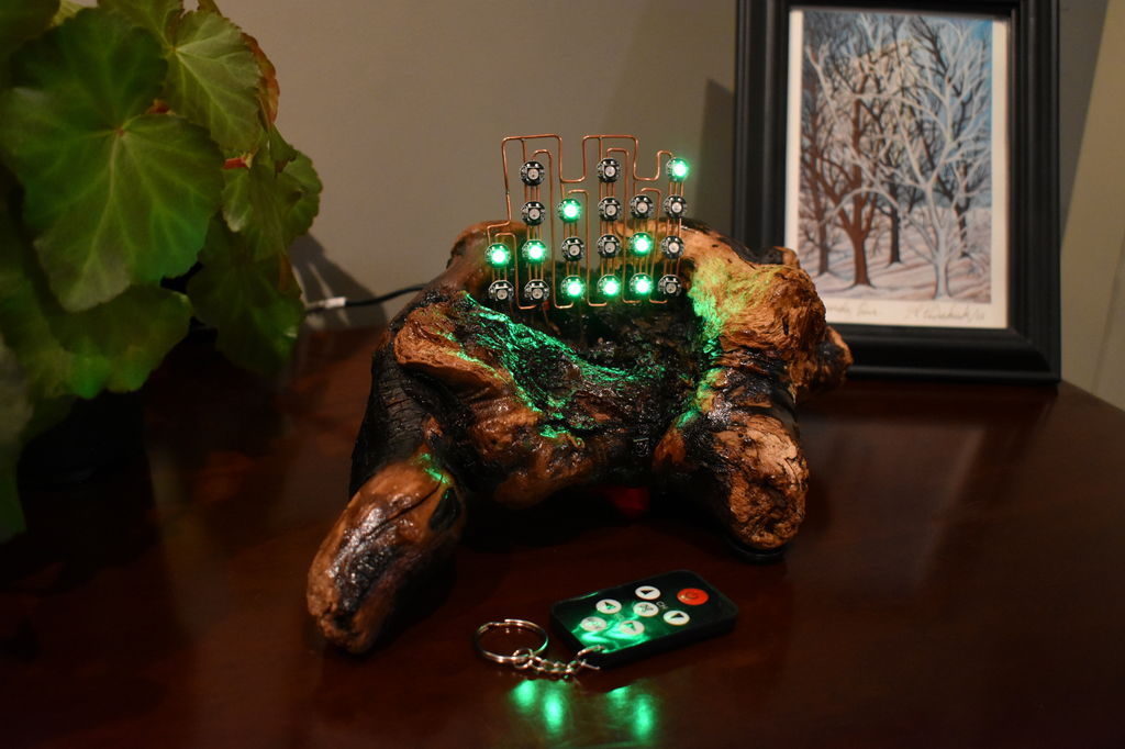
If we’ve learned anything over the years, it’s that hackers like weird clocks, and they love packing as many multicolored LEDs into a device as is humanly possible. Combine both of those concepts into one project, and you’ve got a perfect storm. So as far as unnecessarily complex timepieces go, we’d say the “Crazy Clock 4” built by [Fearless Night] ranks up there among the all-time greats.

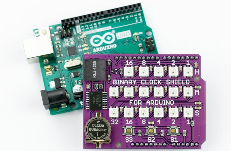
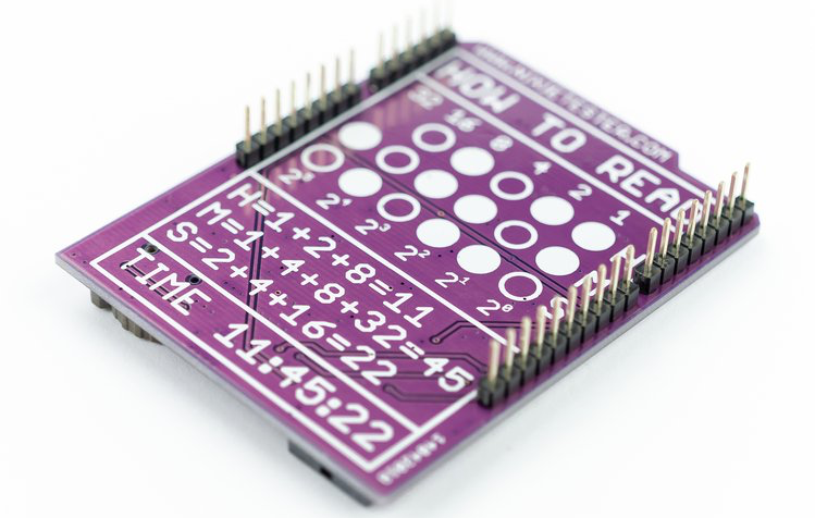
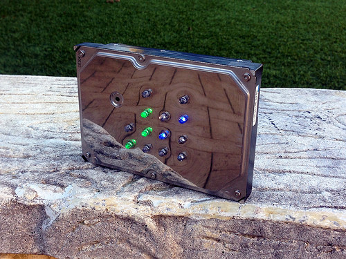
This Arduino Pro Mini powered clock syncs the current time via GPS, with a temperature compensated DS3231 RTC to keep it on the straight and narrow between satellite downlinks. Once the clock has the correct time, how do you read it? Well, at the top you’ve got a basic numerical readout for the normies, and next to that there’s a circular LED display that looks like it could double as a sci-fi movie prop. On the lower level there’s a binary clock for the real show-offs, and as if that wasn’t enough, there’s even dual color-coded analog meters to show the hours and minutes.

[Fearless Night] has provided everything you need to follow along at home, from the Arduino source code to the 3D models of the case and Gerber files for the custom PCB. Personally we think just the top half of the clock would be more than sufficient for our timekeeping needs. If nothing else it should help save some energy, as the clock currently pulls an incredible 20 watts with all those LEDs firing off.

Should you decide to take a walk down memory lane and check out some of the other interesting LED clocks we’ve featured in the past, you’d be busy for quite awhile. But for our money, it’s still hard to beat the impossibly obtuse single-LED clock.

If you want to show everyone your computer prowess—or perhaps get a little practice—binary clocks are a great way to do so. These clocks express time in 1s and 0s instead of 0 through 9, and while the concept is pretty simple, actually creating one is less than straightforward… or used to be.

The Binary Clock Shield, now on Crowd Supply, aims to make this type of clock build extremely easy. This board plugs into an Arduino Uno and features 17 RGB LEDs to act as binary digits, along with an RTC module and backup battery socket. 

The device also includes a piezo speaker for sound output, plus three user buttons, great for setting the time or whatever other unique application you have in mind!

Binary clocks, which use a series of dots to indicate the time, are nothing new, but you’ve never seen anything like this device by Matt Wos! 

Wos’ project features a beautiful driftwood base, and WS2812B RGB LED dots that are suspended above it with copper wire to show the time.

Inside are a pair of Arduino Nanos used to control the LEDs and take input from a small infrared remote, along with an RTC module that allows it to keep accurate time. When the alarm function goes off, you’re treated not to a normal buzzer, but the “soothing” tones of a dial-up modem via an MP3 module and speaker!

Binary clocks have always attracted my attention and here is my version. There are a number of design elements that I believe sets it apart from other variants described on Instructables and other internet sites:

  • Addressable RGB LEDs have been mounted on a copper frame that is external to the body that houses the electronics.
  • An IR remote is used to set the time / alarm, snooze the alarm, select a display colour.
  • The alarm tone is able to be easily personalised.
  • Its in a piece of driftwood!!

The use of the external frame to support the LEDs was due to how much I liked the completed look of the display. The original plan was to have it mounted inside a box, behind opaque perspex but this would have been a design crime!

It’s about time we had another awesome clock post around here. [Mattaw] has liked binary clocks since he was 0 and decided to make one in stunning fashion by using driftwood, nature’s drillable, fillable enclosure.

That beautiful wiring job on the RGB LEDs was done in 18g copper. To keep the LEDs aligned during soldering, he drilled a a grid of holes just deep enough to hold ’em face down. There’s an IR remote to set the time, the color, and choice of alarm file, which is currently set to modem_sound.mp3.

Under the wood, there are a pair of Arduino Nanos, an mp3 decoder board, and an RTC module. Why two Nanos, you ask? Well, the IR interrupts kept, uh, interrupting the LED timing. The remote feature was non-negotiable, so [mattaw] dedicated one Nano to receive remote commands, which it streams serially to the other. Here’s another nice touch: there’s an LDR in one of the nooks or crannies that monitors ambient light so the LEDs are never too bright. Don’t wait another second to check it out—we’ve got 10 videos of it after the break.

Believe it or not, this isn’t the first binary clock we’ve seen.  This honey of a clock uses RGB LEDs to tell the time analog style.

The La Fabrique DIY team has been working on a unique clock modeled after buildings seen along the Seine River in Paris. The “City Clock” is different from the others in that instead of a dial or decimal numbers, windows light up in a binary format, displaying the time in a binary sequence.

Electronics-wise, the clock can be made with an Arduino Uno, involving a fairly simple circuit with individual LEDs and resistors, as seen on this Imgur set. Also shown there is the Kickstarter version of the circuit, which amounts to a sort of gigantic shield that an Arduino Nano is plugged into.

With the City Clock, you calculate the time by adding every digit vertically. The first floor equals one, second equals two, third equals four, and the top equals eight. Using this system, it’s possible to create every digit from zero to nine by adding one number to another.

These clocks are available in various kit forms, including just the electronics or frame if you’d like a head start crafting something truly your own!

As multitools have lots of different functions in one case, so [Shadwan’s] clock design incorporates a multitude of features. He started the design as a binary clock using a Fibonacci spiral for the shape. However, the finished clock has four modes. The original binary clock, an analog clock, a flashlight (all lights on), and a disco mode that strobes multiple lights.

[Shadwan] used Rhino to model the case and then produced it using a laser cutter. The brains are — small wonder — an Arduino. A 3D-printed bracket holds everything together. You can see the result in the video below.

The clock was a school project and used a Neopixel ring. The students had a 16 position ring, which is not enough to do a 24-hour clock so they settled on a 12-hour design. The LED color, however, changes between AM and PM.

The paper included with the design said that research didn’t turn up any other binary clocks using Neopixels. We found that hard to believe, but it might be true. We certainly didn’t find any in our archives, although there are plenty of non-binary clocks out there.


Filed under: Arduino Hacks, clock hacks
Jan
09

Binary Clock Would Make Doc Brown Proud

433MHz, arduino, arduino hacks, ATmega328, binary, binary clock, clock, dcf77, time Comments Off on Binary Clock Would Make Doc Brown Proud 

[Brett] was looking for a way to improve on an old binary clock project from 1996. His original clock used green LEDs to denote between a one or a zero. If the LED was lit up, that indicated a one. The problem was that the LEDs were too dim to be able to read them accurately from afar. He’s been wanting to improve on his project using seven segment displays, but until recently it has been cost prohibitive.

[Brett] wanted his new project to use 24 seven segment displays. Three rows of eight displays. To build something like this from basic components would require the ability to switch many different LEDs for each of the seven segment displays. [Brett] instead decided to make things easier by using seven segment display modules available from Tindie. These modules each contain eight displays and are controllable via a single serial line.

The clock’s brain is an ATmega328 running Arduino. The controller keeps accurate time using a DCF77 receiver module and a DCF77 Arduino library. The clock comes with three display modes. [Brett] didn’t want and physical buttons on his beautiful new clock, so he opted to use remote control instead. The Arduino is connected to a 433MHz receiver, which came paired with a small remote. Now [Brett] can change display modes using a remote control.

A secondary monochrome LCD display is used to display debugging information. It displays the time and date in a more easily readable format, as well as time sync information, signal quality, and other useful information. The whole thing is housed in a sleek black case, giving it a professional look.


Filed under: Arduino Hacks
Jun
15

Binary hard drive clock

[Aaron] has been wanting to build his own binary desk clock for a while now. This was his first clock project, so he decided to keep it simple and have it simply display the time. No alarms, bells, or whistles.

The electronics are relatively simple. [Aaron] decided to use on of the ATMega328 chips he had lying around that already had the Arduino boot loader burned into them. He first built his own Arduino board on a breadboard and then re-built it on a piece of protoboard as a more permanent solution. The Arduino gets the time from a real-time clock (RTC) module and then displays it using an array of blue and green LED’s. The whole thing is powered using a spare 9V wall wort power supply.

[Aaron] chose to use the DS1307 RTC module to keep time. This will ensure that the time is kept accurately over along period of time. The RTC module has its own built-in battery, which means that if [Aaron's] clock should ever lose power the clock will still remember the time. The RTC battery can theoretically last for up to ten years.

[Aaron] got creative for his clock enclosure, upcycling an old hard drive. All of the hard drive guts were removed and replaced with his own electronics. The front cover had 13 holes drilled out for the LED’s. There are six green LED’s to display the hour, and seven blue LED’s for the minute. The LED’s were wired up as common cathode. Since the hard drive cover is conductive, [Aaron] covered both sides of his circuit board with electrical tape and hot glue to prevent any short circuits. The end result is an elegant binary clock that any geek would be proud of.


Filed under: Arduino Hacks


  • Newsletter

    Sign up for the PlanetArduino Newsletter, which delivers the most popular articles via e-mail to your inbox every week. Just fill in the information below and submit.

  • Like Us on Facebook