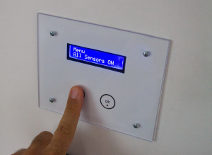
[Trent M. Wyatt]’s CPUVolt library provides a fast way to measure voltage using no external components, and no I/O pin. It only applies to certain microcontrollers, but he provides example Arduino code showing how handy this can be for battery-powered projects.
The usual way to measure VCC is simple, but has shortcomings.
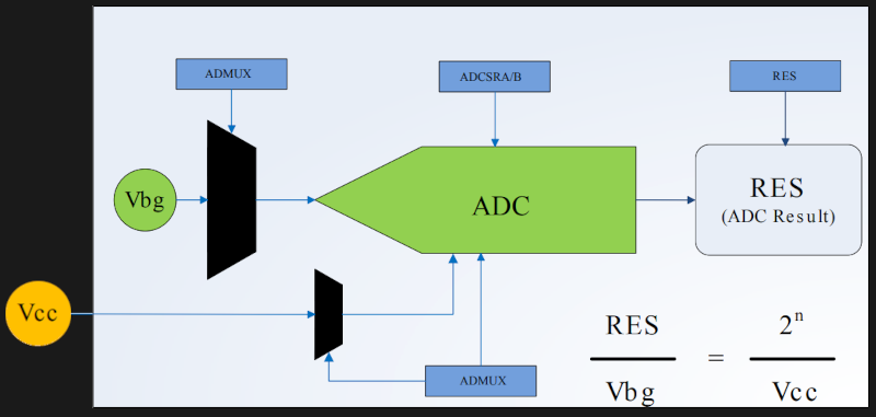
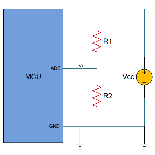
The classical way to measure a system’s voltage is to connect one of your MCU’s ADC pins to a voltage divider made from a couple resistors. A simple calculation yields a reading of the system’s voltage, but this approach has two disadvantages: one is that it constantly consumes power, and the other is that it ties up a pin that you might want to use for something else.
There are ways to mitigate these issues, but it would be best to avoid them entirely. Microchip application note 2447 describes a method of doing exactly that, and that’s precisely what [Trent]’s Arduino library implements.
What happens in this method is one selects Vbg (a fixed internal voltage reference that is temperature-independent) as Vin, and selects Vcc as the ADC’s voltage reference. This is essentially backwards from how the ADC is normally used, but it requires no external hookup and is only a bit of calculation away from determining Vcc in millivolts. There is some non-linearity in the results, but for the purposes of measuring battery power in a system or deciding when to send a “low battery” signal, it’s an attractive solution.
Being an Arduino library, CPUVolt makes this idea very easy to use, but the concept and method is actually something we have seen before. If you’re interested in the low-level details, then check out our earlier coverage which goes into some detail on exactly what is going on, using an ATtiny84.
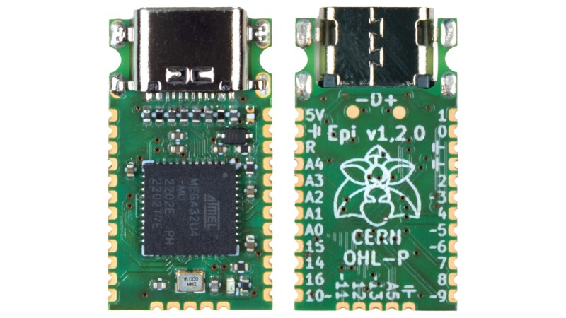
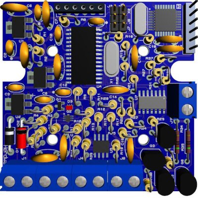
Integrated circuits, chipsets, memory modules, and all kinds of other transistor-based technology continues to get smaller, cheaper, and more energy efficient as time moves on. Not only are the components themselves smaller, but their supporting infrastructure is as well. Computers like the Raspberry Pi are about the size of a credit card and have computing power on the order of full-sized PCs from a few decades ago. The Arduino is no exception to this trend, either, and this new dev board called the Epi 32U4 might be the smallest ATmega platform we’ve seen so far.
As the name suggests, the board is based around the ATmega32U4 which is somewhat unique among Atmel chips in that it includes support for USB within the chip itself rather than relying on external translating circuitry. This makes it an excellent choice for any project which involves sending keyboard, mouse, or other peripheral information to a computer. This goes a few steps further with eliminating “bloat” compared to other boards, too. There’s no on-board voltage regulator, no LEDs except for a single one on pin 13, and even the pins and screw terminals are hemispherical rather than through-hole to save space.
One of the other features this board boasts over other small form factor boards is on-board USB-C, which is definitely a perk as more and more devices switch away from the various forms of older USB-type plugs. The project’s specifications are also available on this GitHub page for anyone that wants to produce their own. And, if you don’t have a 32U4 on hand and still want to build a keyboard project, it’s possible to get some other Arduinos to support these features but it’ll take a little more work.
If you’ve been hanging around microcontrollers and electronics for a while, you’re surely familiar with the concept of the breakout board. Instead of straining to connect wires and components to ever-shrinking ICs and MCUs, a breakout board makes it easier to interface with the device by essentially making it bigger. The Arduino itself, arguably, is a breakout board of sorts. It takes the ATmega chip, adds the hardware necessary to get it talking to a computer over USB, and brings all the GPIO pins out with easy to manage header pins.
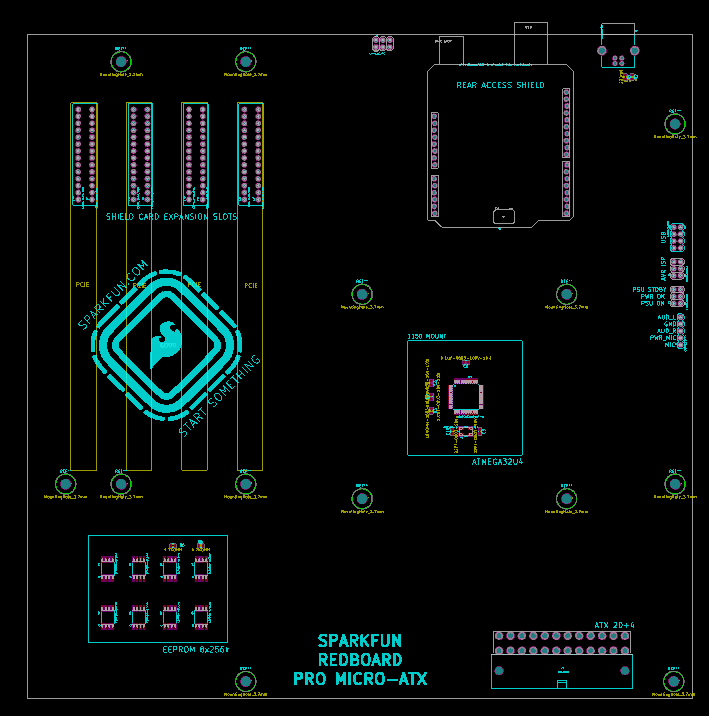
But what if you wanted an even bigger breakout board for the ATmega? Something that really had some leg room. Well, say no more, as [Nick Poole] has you covered with his insane RedBoard Pro Micro-ATX. Combining an ATmega32u4 microcontroller with standard desktop PC hardware is just as ridiculous as you’d hope, but surprisingly does offer a couple tangible benefits.
RedBoard PCB layout
The RedBoard is a fully compliant micro-ATX board, and will fit in pretty much any PC case you may have laying around in the junk pile. Everything from the stand-off placement to the alignment of the expansion card slots have been designed so it can drop right into the case of your choice.
That’s right, expansion slots. It’s not using PCI, but it does have a variation of the standard Arduino “shield” concept using 28 pin edge connectors. There’s a rear I/O panel with a USB port and ISP header, and you can even add water cooling if you really want (the board supports standard LGA 1151 socket cooling accessories).
While blowing an Arduino up to ATX size isn’t exactly practical, the RedBoard is not without legitimate advantages. Specifically, the vast amount of free space on the PCB allowed [Nick] to add 2Mbits of storage. There was even some consideration to making removable banks of “RAM” with EEPROM chips, but you’ve got to draw the line somewhere. The RedBoard also supports standard ATX power supplies, which will give you plenty of juice for add-on hardware that may be populating the expansion slots.
Musicians have an array of electronic tools at their disposal to help make music these days. Some of these are instruments in and of themselves, and [Wai Lun] — inspired by the likes of Choke and Shawn Wasabi — built himself a midi fighter
Midi fighters are programmable instruments where each button can be either a note, sound byte, effect, or anything else which can be triggered by a button. [Lun]’s is controlled by an ATmega32u4 running Arduino libraries — flashed to be recognized as a Leonardo — and is compatible with a number of music production programs. He opted for anodized aluminum PCBs to eliminate flex when plugging away and give the device a more refined look. Check it out in action after the break!
[Lun] designed the project in Fusion 360 and KiCad with plenty of room to spare for some electronic art — gotta love Daft Punk. He’s using Sanwa OBSC 24mm arcade buttons for their premium quality and two SK6812 mini LEDs apiece for a slick lighting effect when they’re pressed.
After receiving the manufactured boards and parts, a quick test fit flowed right into final assembly. With the ATmega32u4 flashed and programmed, he was ready to rock. Down the line, [Lun] wants to have a GUI to configure the notes each button plays without tinkering around in the code, but it works great for now.
For an astounding acoustic to electronic instrument conversion, check out this MIDI accordion!
I am a crappy software coder when it comes down to it. I didn’t pay attention when everything went object oriented and my roots were always assembly language and Real Time Operating Systems (RTOS) anyways.
So it only natural that I would reach for a true In-Circuit-Emulator (ICE) to finish of my little OBDII bus to speed pulse generator widget. ICE is a hardware device used to debug embedded systems. It communicates with the microcontroller on your board, allowing you to view what is going on by pausing execution and inspecting or changing values in the hardware registers. If you want to be great at embedded development you need to be great at using in-circuit emulation.
Not only do I get to watch my mistakes in near real time, I get to make a video about it also.
Getting Data Out of a Vehicle
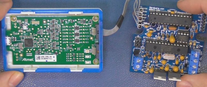
I’ve been working on a small board which will plug into my car and give direct access to speed reported on the Controller Area Network (CAN bus).
To back up a bit, my last video post was about my inane desire to make a small assembly that could plug into the OBDII port on my truck and create a series of pulses representing the speed of the vehicle for my GPS to function much more accurately. While there was a wire buried deep in the multiple bundles of wires connected to the vehicle’s Engine Control Module, I have decided for numerous reasons to create my own signal source.
At the heart of my project is the need to convert the OBDII port and the underlying CAN protocol to a simple variable representing the speed, and to then covert that value to a pulse stream where the frequency varied based on speed. The OBDII/CAN Protocol is handled by the STN1110 chip and converted to ASCII, and I am using an ATmega328 like found on a multitude of Arduino’ish boards for the ASCII to pulse conversion. I’m using hardware interrupts to control the signal output for rock-solid, jitter-free timing.
Walk through the process of using an In-Circuit Emulator in the video below, and join me after the break for a few more details on the process.
The Hardware
I revised the board since the last video and removed the support for the various protocols other than CAN, which is the non-obsolete protocol of the bunch. By removing a bunch of parts I was able to change the package style to through-hole which is easier for many home hobbyists, so you can leave the solder-paste in the ‘fridge.
The “Other Connector” on your Arduino
Unlike the Arduino which is ready to talk to your USB port when you take it out of the box, the ATmega chips arrive without any knowledge of how to go and download code, in other words it doesn’t have a boot loader. Consequently I have the In-Circuit-Serial-Programming (ICSP) pins routed to a pin header on my board so that I can program the part directly.
On this connector you’ll find the Reset line, which means with this header I can use a true ICE utilizing the debugWIRE protocol. Since the vast majority of designs that use an AVR chip do not repurpose the reset pin for GPIO, it is a perfect pin to use for ICE. All of the communications during the debug process will take place on the reset pin.
Enter the ICE
When designing a computer from scratch there is always the stage where nothing yet works. Simply put, a microprocessor circuit cannot work until almost every part of the design works; RAM, ROM, and the underlying buses all need to (mostly) work before simple things can be done. As a hardware engineer by trade I would always reach for an ICE to kick off the implementation; only after the Beta release would the ICE start to gather dust in the corner.
In the case of the ATmega, the debugging capabilities are built into the microcontroller itself. This is a much more straightforward implementation than the early days when we had to have a second isolated processor running off-board with its own local RAM/ROM.
One note mentioned in the video is that a standard Arduino’ish board needs to have the filter capacitors removed from the RESET line to allow the high speed data on the line for its debugWIRE usage.
The ICE I am using here is the one made by Atmel, and is compatible with Atmel Studio, there are also other models available such as the AVR Dragon.
ICEyness
The ICE allows us to download and single step our code while being able to observe and overwrite RAM and I/O Registers from the keyboard. We are able to watch the program step by step or look underneath at the actual assembly code generated by the compiler. We can watch variables and locations directly in RAM or watch the C language counterparts. It’s also possible to jump over a sub-routine call in the instance of just wanting to see the result without all of the processing.
This video was really about finishing the OBDII circuit so I didn’t really have the time to go over everything an ICE can do, maybe I will do a post dedicated to just the ICE and development environment next time.
Putting an full microcontroller platform in a DIP format is nothing new – the Teensy does it, the Arduino nano does it, and a dozen other boards do it. [Alex] and [Alexey] aren’t content with just a simple microcontroller breakout board so they’re adding a radio, an OLED, an SD card reader, and even more RAM to the basic Arduino platform, all in a small, easy to use package.
The DIPDuino, as [Alex] and [Alexy] are calling it features an ATmega1284 processor. To this, they’re adding a 128×32 pixel OLED, a micro SD slot, and 1Mbit of SRAM. The microcontroller is a variant that includes a 2.4 GHz Zigbee radio that allows for wireless connections to other DIPDuinos.
What are [Alex] and [Alexey] going to do with their cool little board? They’re planning on using the OLED for a watch, improve their software so the firmware can be updated from the SD card, and one of [Alex]’s friends wants to build a RepRap controller with one of these. There’s a lot of potential with this board, and we’re interested in seeing where the guys take the project from here.
Arduino is one of those boards that has become synonymous with hacking and making. Since its introduction in 2005, over 700,000 official Arduino boards have been sold, along with untold millions of compatible and clone boards. Hackers and makers around the world have found the Arduino platform a cheap and simple way to get their projects off the ground. This weeks Hacket focuses on some of the best Arduino based projects we’ve found on Hackday.io!
[Niazangels] gets the ball – or ballpoint pen – rolling with Roboartist, a robot which creates line drawings. Roboartist is more than just a plotter though. [Niazangels] created a custom PC program which creates line drawings from images captured by a webcam. The line drawings are converted to coordinates, and sent to an Arduino, which controls all the motors that move the pen. [Niazangels] went with Dynamixel closed loop servo motors rather than the stepper motors we often see in 3D printers.
[Peter Edwards] is preserving the past with Tapuino, the $20 C64 Tape Emulator. Plenty of programs for the Commodore 64, 128, and compatibles were only distributed on tape. Those tapes are slowly degrading, though the classic Commodore herdware is still going strong. Tapuino preserves those tapes by using an Arduino nano to play the files from an SD card into the original Datasette interface. [Peter] also plans to add recording functionality to the Tapuino, which will make it the total package for preserving your data. All that’s missing is that satisfying clunk when pressing the mechanical Play button!
[Dushyant Ahuja] knows what time it is, thanks to his Infinity Mirror Clock. This clock tells time with the help of some WS2812B RGB LED. [Dushyant] debugged the clock with a regular Arduino, but when it came time to finish the project, he used an ATmega328 to create an Arduino compatible board from scratch. Programming is easy with an on-board Bluetooth module. [Dushyant] plans to add a TFT lcd which will show weather and other information when those power-hungry LEDs are switched off.
[IngGaro] built an entire home alarm system with his project Arduino anti-theft alarm shield. [IngGaro] needed an alarm system for his home. That’s a lot to ask of a standard ATmega328p powered Arduino Uno. However, the extra I/O lines available on an Arduino Mega2560 were just what the doctor ordered. [IngGaro] performed some amazing point-to-point perfboard wiring to produce a custom shield that looks and works great! The alarm can interface with just about any sensor, and can be controlled via the internet. You can even disarm the system through an RFID keycard.
Want MORE Arduino in your life? Check out our curated Arduino List!
That’s about all the millis() we have for this weeks Hacklet. As always, see you next week. Same hack time, same hack channel, bringing you the best of Hackaday.io!
While newer Arduinos and Arduino compatibles (including the Hackaday.io Trinket Pro. Superliminal Advertising!) either have a chip capable of USB or rely on a V-USB implementation, the old fogies of the Arduino world, the Uno and Mega, actually have two chips. An ATMega16u2 takes care of the USB connection, while the standard ‘328 or ‘2560 takes care of all ~duino tasks. Wouldn’t it be great is you could also use the ’16u2 on the Uno or Mega for some additional functionality to your Arduino sketch? That’s now a reality. [Nico] has been working on the HoodLoader2 for a while now, and the current version give you the option of reprogramming the ’16u2 with custom sketches, and use seven I/O pins on this previously overlooked chip.
Unlike the previous HoodLoader, this version is a real bootloader for the ’16u2 that replaces the DFU bootloader with a CDC bootloader and USB serial function. This allows for new USB functions like HID keyboard, mouse, media keys, and a gamepad, the addition of extra sensors or LEDs, and anything else you can do with a normal ‘duino.
Setup is simple enough, only requiring a connection between the ‘328 ISP header and the pins on the ’16u2 header. There are already a few samples of what this new firmware for the ’16u2 can do over on [Nico]’s blog, but we’ll expect the number of example projects using this new bootloader to explode over the coming months. If you’re ever in an Arduino Demoscene contest with an Arduino and you’re looking for more pins and code space, now you know where to look.
Stephen Wylie , “Program two ATmegas w/an Arduino & AVRDUDE without re-cabling in between!”
Those of you who have programmed an Arduino through the Arduino or AVR Studio IDE may have noticed the utility that is really doing the work: AVRDUDE (AVR Downloader/UploaDEr). This is a powerful program that can facilitate programming new sketches on top of a bootloader, load a brand new bootloader or chip image, capture the current firmware programmed on the chip, and set fuse bits (which can render your chip unusable without special tools if you’re not careful).
These days, it’s easy enough to play games on the go. If you have a smart phone, you are pretty much set. That doesn’t mean you can’t still have fun designing and building your own portable gaming system, though.
[randrews] did just that. He started out by purchasing a small memory LCD display from Adafruit. The screen he chose is low power as far as screens go, so it would be a good fit for this project. After testing the screen with a quick demo program, it was time to start designing the circuit board.
[randrews] used Eagle to design the circuit. He hand routed all of the traces to avoid any weird issues that the auto router can sometimes cause. He made an efficient use of the space on the board by mounting the screen over top of the ATMega chip and the other supporting components. The screen is designed to plug in and out of the socket, this way it can be removed to get to the chip. [randrews] needs to be able to reach the chip in order to reprogram it for different games.
Once the board design was finished, [randrews] used his Shapeoko CNC mill to cut it out of a copper clad board. He warns that you need to be careful doing this, since breathing fiberglass dust is detrimental to living a long and healthy life. Once the board was milled out, [randrews] used a small Dremel drill press to drill all of the holes.
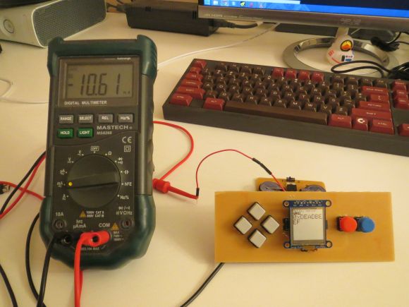
The final piece of the puzzle was to figure out the power situation. [randrews] designed a second smaller PCB for this. The power board holds two 3V coin cell batteries. The Arduino expects 5V, so [randrews] had to use a voltage regulator. This power board also contains the power switch for the whole system.
The power board was milled and populated. Then it was time to do some measurements. [randrews] measured the current draw and calculates that he should be able to get around 15 hours of play time using the two 3V coin cell batteries. Not bad considering the size.
Planet Arduino is, or at the moment is wishing to become, an aggregation of public weblogs from around the world written by people who develop, play, think on Arduino platform and his son. The opinions expressed in those weblogs and hence this aggregation are those of the original authors. Entries on this page are owned by their authors. We do not edit, endorse or vouch for the contents of individual posts. For more information about Arduino please visit www.arduino.cc
You are currently browsing the archives for the ATmega category.