
13
Getting Started with Arduino – Chapter Ten
arduino, Arduino Tutorial, ATmega, ATmega328, bootrom, education, learning electronics, microcontrollers, Relay, timing systems, tronixstuff, Uncategorized Comments Off on Getting Started with Arduino – Chapter Ten
This is part of a series titled “Getting Started with Arduino!” by John Boxall – A tutorial on the Arduino universe.
The first chapter is here.
Welcome back fellow arduidans!
This week we will minimise an Arduino Duemilanove board, use time to control, and then mix all of that up. The hardware, not the readers… ![]()
So let’s go!
As time goes by, you will want to build projects to use away from the bench, or that are permanent. Although doing so is infinitely fun, it can become expensive if you keep buying Arduino boards for each project or proof-of-concept prototype, or even finished products. However, as always, the Arduino team have solved this problem for us as well. The actual microcontroller integrated circuit (e.g. ATmega328P-PU) can operate with a lot less circuitry than that is contained on your Duemilanove or compatible board. In fact, you can have a functioning Arduino system with three components and a 5V power supply.
How?
To start, please download the Duemilanove schematic from here. Upon glancing at it for the first time, there seems to be a lot of things required. However if you just want to use the digital and analogue pins, you can cut that schematic down to a lot less, however you need to make a couple of changes to how you upload the sketch. Here is what you can get away with:

X1 is the 16 MHz resonator. Using only the main circuit on the left, to upload your sketch you need to place the ATmega chip in your Arduino board, upload the sketch, then very carefully remove the chip and place it into your circuit, breadboard, etc. Please make sure to observe anti-static precautions, and always use a chip puller (below).

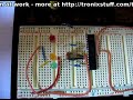
Furthermore, if you only have one chip, it would be very wise to have a second or third as a backup. A programmed ATmega with the Arduino bootloader can be had for less than US$6. Below is a shot of my barebones Arduino system at work. It is setup to run this basic example: example 10.1.pdf

The blue and yellow wires run off to a 5 volt power supply. And here is it working:
To recreate this at home, you will need:
- One ATmega328P-PU microcontroller with Arduino bootrom
- solderless breadboard
- 10k ohm resistor
- 16 MHz resonator
- (optional – for USB cable) 6-pin header pin
- (optional – for USB cable) 0.1 uF ceramic capacitor
- (optional – for USB cable) FTDI cable (the 5 volt version!)
A note about the resonator. Your Arduino board will most likely have a metal crystal, however a resonator is a little cheaper and easier to use, as it has the capacitors in built. If you look at the Arduino schematic, they use a crystal and two 22 picofarad capacitors. So if you use the resonator, pins 1 and 3 go to chip pins 9 and 10, and resonator pin 2 goes to GND. Here is the data sheet for the resonator. They should be easily available, for example from here or here. The USB cable option will make life a lot easier. The cable is called an FTDI cable, and contains the electronics within to interface between the USB port on your computer and the TX/RX pins on the microcontroller. The wiring details are in the schematic above. Inside the cable can roughly be described as this part of the Arduino board:

The cable contains the FTDI chip circuitry and so on. It also supplies power whilst programming, or leaving the cable plugged in. Here is my board with the extra wiring connected:

So if you have this kind of setup, you can just plug the cable into the computer USB port and upload sketches as normal. However there are some modifications that may need to be done with your computer’s operating system to make it work. If you are running Linux or MacOS, please visit here; if you are running windows of some sort, go to device manager, right click the USB serial port you are using, select properties, port-settings tab, advanced, and turn on set RTS on Close.
When purchasing an FTDI cable – make sure you get the 5 volt version! ![]() So now you can integrate the Arduino chip into your prototypes much easier and cheaper. However, if you are going to use SPI or I2C devices, more circuitry will be required. We will examine creating these interfaces in more detail later. A good compromise in this situation may be a barebones Arduino product such as a Boarduino, or Arduino Pro Mini.
So now you can integrate the Arduino chip into your prototypes much easier and cheaper. However, if you are going to use SPI or I2C devices, more circuitry will be required. We will examine creating these interfaces in more detail later. A good compromise in this situation may be a barebones Arduino product such as a Boarduino, or Arduino Pro Mini.

Next on the agenda is a small project to consolidate some previous learning. At the end of chapter nine, we made a (relatively) user friendly clock with an alarm. And in chapter three, we controlled a relay with our arduino. So now we have the ability to create our own on/off timer of which possible uses could be limitless.
In doing so, we can start by modifying the sketch from exercise 9.3. It has the ability to set an alarm time (let’s call it a start time from now on), so we can add the ability to set an end time – it just requires some more variable to store the end time data, and another menu function to set these. Finally, another function is required to check if it is time to turn off (basically identical to the checkalarm() function.
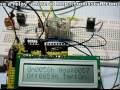
The hardware side of things for the example will be quite simple as well, below is my schematic, and the basic board:


I am using 12v relays as currently that is all I have in stock. The 12V power supply is just an LM7812 regulator from a 20V DC plugpack. For demonstration purposes any low-voltage relay would be fine. A 5V relay such as this would be perfect as you could run it from the Arduino’s 5V rail.
Note: From here on you understand that one can use an arduino to switch a very high current and/or voltage with some relays. Please exercise care and consult a qualified, licensed person if you are working with mains voltage (100~250V AC… the stuff that comes out of power points/outlets). They can KILL you!
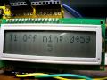
So for this example, I have modified the sketch as described earlier to accept a start time, end time, and display relevant data on the screen. It will switch on and off the relay, which controls a light globe drawing 100mA – 5 times the current an Arduino digital out pin can deliver. It only operates using 24-hour time, to save user confusion. You could control anything as long as you do not exceed the current and voltage maximums for your particular relay.
So here it is in action. The time has already been set previously, so you can watch the setting of the on/off time, and watch it in action. You can skip ahead from 01:03s to 01:48s to save time.
and here is the sketch for your perusal: example 10.2.pdf.
As as example the user interface wasn’t that flash, but naturally it can be worked on to be more intuitive. So now it is your chance to do so, with…
Exercise 10.1
Create a timing system for a hypothetical lighting system that controls two independent circuits. Each timer can turn on or off at a specified time, either daily, only on weekdays, only on a certain day of the week (e.g. only Fridays) or only on weekends. The menu system should be easy and quick to use.
For the purpose of the exercise, you can switch on or off an LED to represent each lighting circuit – you already know how to use the relays.
You will need:
- Your standard Arduino setup (computer, cable, Duemilanove)
- Two usual LEDs of your choice
- 2 x 560 ohm 0.25 W resistors. For use as current limiters between the LEDs and ground
- 1 x 10k resistor
- one push button
- a breadboard and some connecting wire
- some water
- DS1307 timer IC circuit components (see this schematic from chapter seven) or a pre-built module
- one 10k linear potentiometer
- LCD module as per chapter two
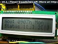
Here are some videos of my interpretation. To save time I have not connected the LEDs, however timer running status is indicated on the second line of the display – an “!” is shown when a circuit has been activated. The first video shows setting the real time, timer data and displaying the results:
and the sketch: exercise 10.1.pdf.
How did you go? With a little more hardware this exercise could become a real product – you could control sprinkler systems instead of lights, thermostats, anything is really possible. Having a larger LCD screen would help with the user interface, perhaps a 20 character by 4 line unit. As long as such a screen has the standard HD44780 interface, you would be fine.
![]()
Due to unforeseen circumstances, this week’s chapter has been shorter than usual, and for that – I apologise.
However, kindly subscribe (see the top right of this page) to receive notifications of new articles.
High resolution photos are available from flickr.
If you have any questions at all please leave a comment (below). We also have a Google Group dedicated to the projects and related items on the website – please sign up, it’s free and we can all learn something. If you would like to showcase your work from this article, email a picture or a link to john at tronixstuff dot com. You might even win a prize!
Don’t forget to check out the range of gear at Little Bird Electronics!
So have fun, stay safe and see you soon for our next instalment!


