Posts | Comments

Planet Arduino

Archive for the ‘SI5351’ Category

In retrocomputing circles, it’s often the case that the weirder and rarer the machine, the more likely it is to attract attention. And machines don’t get much weirder than the DEC Rainbow 100-B, sporting as it does both Z80 and 8088 microprocessors and usable as either a VT100 terminal or as a PC with either CP/M or MS-DOS. But hey — at least it got the plain beige box look right.

Weird or not, all computers have at least a few things in common, a fact which helped [Dr. Joshua Reichard] home in on the problem with a Rainbow that was dead on arrival. After a full recapping — a prudent move given the four decades since the machine was manufactured — the machine failed to show any signs of life. The usual low-hanging diagnostic fruit didn’t provide much help, as both the Z80 and 8088 CPUs seemed to be fine. It was then that [Joshua] decided to look at the heartbeat of the machine — the 24-ish MHz clock shared between the two processors — and found that it was flatlined.

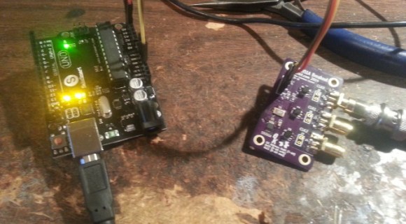
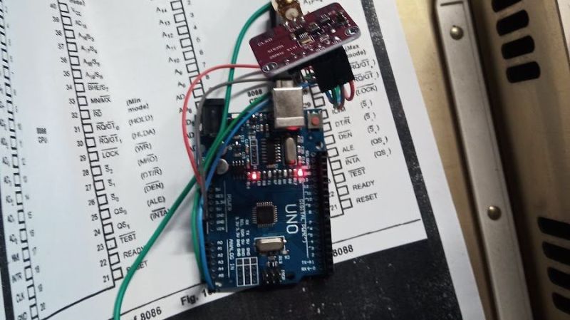
Unwilling to wait for a replacement, [Joshua] cobbled together a temporary clock from an Arduino Uno and an Si5351 clock generator. He connected the output of the card to the main board, whipped up a little code to generate the right frequency, and the nearly departed machine sprang back to life. [Dr. Reichard] characterizes this as a “defibrillation” of the Rainbow, and while one hates to argue with a doctor — OK, that’s a lie; we push back on doctors all the time — we’d say the closer medical analogy is that of fitting a temporary pacemaker while waiting for a suitable donor for a transplant.

This is the second recent appearance of the Rainbow on these pages — [David] over at Usagi Electric has been working on the graphics on his Rainbow lately.

A radio receiver is always a fun project. [Jayakody2000lk] decided that his new superheterodyne design would use an Arduino and it looks like it came out very nicely. The system has four boards. An off-the-shelf Arduino, a Si5351 clock generator board (also off-the-shelf), and two custom boards that contain the IF amplifier and mixer.

The receiver started out in 2015 without the Arduino, and there’s a link in the post to that original design. Using the Si5351 and the Arduino replaces the original local oscillator and their have been other improvements, as well. You can see a video about the receiver below.

Tuning is by a rotary encoder and the current software lets you tune from about 4.75 MHz to a little over 15.8 MHz. Of course, you could change to any frequency the Si5351 can handle as long as the mixer and other components can handle it. The IF frequency is the usual 455 kHz.

If you decide to build this yourself, the design files are on GitHub. Overall a very nice and neat design. We are always amazed how little radio architecture has changed since Edwin Armstrong’s day. Of course, we have better components, even if they aren’t meant for radio purposes.

[Tom Hall], along with many hams around the world, have been hacking the Silicon Labs Si5351 to create VFOs (variable frequency oscillators) to control receivers and transmitters. You can see the results of his work in a video after the break.

vfo board
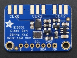
[Tom] used a Teensy 3.1 Arduino compatible board, to control the Si5351 mounted on an Adafruit breakout board. An LCD display shows the current frequency and provides a simple interface display for changing the output. A dial encoder allows for direct adjustment of the frequency. The ham frequency band and the frequency increment for each encoder step are controlled by a joystick. When you get into the 10 meter band you definitely want to be able to jump by kHz increments, at least, since the band ranges from 28 mHz to 29.7 mHz.

So what is the Si5351? The data sheets calls it an I2C-Programmable Any-Frequency CMOS Clock Generator + VCXO. Phew! Let’s break that down a bit. The chip can be controlled from a microprocessor over an I2C bus. The purpose of the chip is to generate clock outputs from 8 kHz to 160 kHz. Not quite any frequency but a pretty good range. The VCXO means voltage controlled crystal oscillator. The crystal is 25 mHz and provides a very stable frequency source for the chip. In addition, the Si5351 will generate three separate clock outputs.

[Tom] walks through the code for his VFO and provides it via GitHub. An interesting project with a lot of the details explained for someone who wants to do their own hacks. His work is based on work done by others that we’ve published before, which is what hacking is all about.


Filed under: Arduino Hacks, radio hacks

Historically when hams built low power (QRP) transmitters, they’d use a crystal to set the frequency. Years ago, it was common to find crystals in all sorts of radios, including scanners and handheld transceivers. Crystals are very stable and precise and it is relatively easy to make a high quality oscillator with a crystal and a few parts.

The big problem is you can’t change the frequency much without changing crystals. Making a high quality variable frequency oscillator (VFO) out of traditional components is quite a challenge. However, today you have many alternatives ranging from digital synthesis to all-in-one IC solutions that can generate stable signals in a wide range of frequencies.

[N2HTT] likes to build radio projects and he decided to take an Si5351 clock generator and turn it into a three frequency VFO for his projects. The Si5351 uses a crystal, so it is very stable. However, you can digitally convert that crystal frequency into multiple frequencies over a range of about 8kHz to 160MHz.

The chip has two PLLs that multiply the crystal frequency by a programmable amount. Then you can set each channel to start with the crystal frequency or either PLL and divide it by an integer or a fractional amount. As you might expect, the integer divisions result in a more stable output, but if you really need a particular frequency and can accept some jitter, you can get almost anything you want out of the device.

The device [N2HTT] used is in a tiny 10 pin MSOP package, but there are plenty of inexpensive breakout boards available. You control all the multiplying and dividing by sending configuration data to the chip via I2C. There’s even a software package that can tell you the best settings for the frequencies you want to generate.

One thing of interest is the breadboard the VFO is built on. [N2HTT] used an Arduino and a small display along with an encoder to control the chip. But the chip generates some high frequencies and common wisdom is that solderless breadboards aren’t good for high frequency. Acting on a tip he read in a magazine article [N2HTT] took a bamboo cutting board and then affixed standard solderless breadboards to unetched copper PCB material. He then made sure the PCB ground planes were well connected and grounded. It seems to work (you can see it working in the video below).

The output of the chip is a square wave, so if you wanted to use it for radio applications, you’d probably have to low pass filter the output to get a sine wave. The device is only as accurate as the crystal and will exhibit some phase noise and jitter (especially if you don’t have integer divisions). However, having a wide range programmable frequency source for a few bucks is a great building block for lots of different projects.

In fact, we covered a project to use the same part to implement a digital communications mode a few months ago. There’s also more than one Arduino library out there. Since it is I2C, you can use it with many other processors, too.


Filed under: Arduino Hacks, wireless hacks

[jmilldrum] really gets a lot of use out of his Si5351A breakout board. He’s a ham [NT7S], and the Si5351A can generate multiple square waves ranging from 8 kHz to 160 MHz, so it only stands to reason that it is going to be a useful tool for any RF hacker. His most recent exploit is to use the I2C-controllable chip to implement a Fast Simple QSO (FSQ) beacon with an Arduino.

FSQ is a relatively new digital mode that uses a form of low rate FSK to send text and images in a way that is robust under difficult RF propagation. There are 32 different tones used for symbols so common characters only require a single tone. No character takes more than two tones.

The Si5351A can easily handle the encoding job. Since the output is a square wave, you do need a low-pass filter to put it on the air. [jmilldrum] also used some relatively small amplifiers to get the output up to 20 watts.

You might remember, we’ve talked about [jmilldrum’s] work with the Si5351A before. We also recently were talking about hams experimenting with digital modes and this is a great example, both by the developers of FSQ and [jmilldrum] for implementing it with an Arduino. If you want to learn more about FSQ, see the video below.


Filed under: Arduino Hacks, radio hacks, wireless hacks
Jun
27

Generate Clocks with the SI5351 and an Arduino

arduino, arduino hacks, clock, PLL, radio, radio hacks, SI5351 Comments Off on Generate Clocks with the SI5351 and an Arduino 

A SI5351 clock generator chip and an Arduino

If you’re dealing with RF, you’ll probably have the need to generate a variety of clock signals. Fortunately, [Jason] has applied his knowledge to build a SI5351 library for the Arduino and a breakout board for the chip.

The SI5351 is a programmable clock generator. It can output up to eight unique frequencies at 8 kHz to 133 MHz. This makes it a handy tool for building up RF projects. [Jason]‘s breakout board provides 3 isolated clock outputs on SMA connectors. A header connects to an Arduino, which provides power and control over I2C.

If you’re looking for an application, [Jason]‘s prototype single-sideband radio shows the chip in action. This radio uses two of the SI5351 clocks: one for the VFO and one for the BFO. This reduces the part count, and could make this design quite cheap.

The Arduino library is available on Github, and you can order a SI5351 breakout board from OSHPark.


Filed under: Arduino Hacks, radio hacks


  • Newsletter

    Sign up for the PlanetArduino Newsletter, which delivers the most popular articles via e-mail to your inbox every week. Just fill in the information below and submit.

  • Like Us on Facebook