Hello readers!
Today we are going to examine the 74HC4066 quad bilateral switch IC. My reason for writing this comes from a comment left by a reader on chapter nine of the Arduino tutorial. They suggested using a 4066 IC to control the cathodes of the LED matrix instead of resistors and NPN transistors. This was a good suggestion, however the 4066 can only switch a current of 10mA per pin. Luckily the 74HC4066 can handle up to 25mA per switch – so we’ll look into this instead.
First of all, let’s say hello:

This is the 14-pin DIP package. It is also available in surface mount, and other newer package styles. Although we are looking at an example from NXP, according to my main component supplier (Farnell/Newark) this IC is also manufactured by Texas Instruments, ON Semi, ST Microelectronics and Fairchild.
So, what is a quad-bilateral switch? Four switches in one IC. Here is a diagram:
 Imagine a simple normally-open push button. You press the button, and current can flow through the switch. Using the 74HC4066, when current is applied to the E pin, current can pass through from the matching Y pin to the Z pin. As you can see above, there are four of these switches in the IC. This is where the benefit of the IC comes to mind, normally one might use a 1k ohm resistor and an NPN switching transistor as an electronic switch, and I have done so myself. But when you need a few of them, it can be easier to start using these 74HC4066s as long as the current requirements are met.
With regards to the current the IC can switch, Is, the maximum is 25mA per switch. This is more than enough to run a typical LED, TTL logic gate, etc. The other interesting parameter is the turn-on and turn off times – at 6 volts it can turn on in around 10 nanoseconds and turn off at around 13 nanoseconds (so a rough calculation – say it takes 30 nanoseconds to switch on and then switch off, that’s 33.3 million times per seconds (33.3 MHz). All these parameters and more are available from the data sheet (pdf). Someone correct me if I’m wrong!
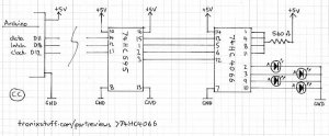
That’s enough theory – let’s put it to work now. Our first demonstration is quite simple – just switch on and off some LEDs via a 74HC595 shift register and an Arduino. We send a number (0, 1, 2, 4, 8 ) to the shift register, which stays off, then sets pins Q0, Q1, Q2, Q3 high in order, which in turn activate the switches 1~4 on the 74HC4066. The 74HC4066 sends a current to each LED connected to the switch outputs.
Here is the schematic:
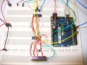
Laid out on the breadboard:
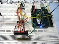
And the ubiquitous video:
And here is the Arduino sketch: demo1.pdf. Well that was interesting. I know these simple demonstrations may be… well a little simple, but after taking the time to build them from scratch you get a better understanding of the part and how they work. Practice makes perfect and all that. Anyhow, let’s have a look at something much more interesting – a very basic (!) digital to analogue converter. Consider the circuit below:
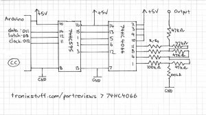
The 74HC4066 switches creates a final voltage through the sum of various currents being switched into the final output. First of all, here is a video of the switches being turned on and off one at a time:
and the corresponding Arduino sketch:demo2.pdf. The next video shows the results of sending decimal numbers 0~15 to the shift register – in effect continually adding the outputs of the pins until all pins are on, then in reverse:
and the corresponding Ardiono sketch:demo3.pdf.
Well I hope you found this part review interesting, and helped you think of something new to make. In conclusion I would consider the 74HC4066 easier and quicker for end user to use in projects (less pins to solder, etc) however using it could cost more depending on the volume required. Furthermore, this would only apply if the current restrictions of the IC are met.

As always, thank you for reading and I look forward to your comments and so on. Furthermore, don’t be shy in pointing out errors or places that could use improvement. Please subscribe using one of the methods at the top-right of this web page to receive updates on new posts. Or join our new Google Group. High resolution photos are available on flickr.
Otherwise, have fun, be good to each other – and make something! 
Notes: In writing this post, I used information from NXP, plus information and circuit inspiration from various books by Forrest Mims III.
Thank you!


