The Arduino Project Hub (powered by Hackster.io) is a community dedicated to discovering how fun and rewarding tinkering with electronics and software can be, so any project made with Arduino and Genuino boards is welcome! Each day, the Arduino Team will select some of the best tutorials and highlight them on our social channels.
The Arduino Project Hub is also a great place to keep your latest projects and easily share them with your friends, students and the rest of the community!
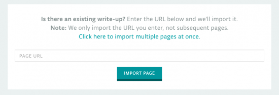
If you have tutorials and articles on other platforms, we’ve got some good news! There is a cool import function so you can just paste the link and we’ll take care of the transfer. When you click on ‘New Project’ you will be presented with two options, create a tutorial from scratch or import one via URL.
We first thought [Alexis Ospitia]’s watch was a sports watch made with an Arduino, but it’s actually a sporty watch made with an Arduino. This explains the watch’s strange ability to tell you the current temperature and humidity.
The core of the watch is an Arduino Mini. To make it good for time telling, a real-time clock module was added. A DHT11 monitors the temperature and humidity. A charge circuit and lithium battery provide power. Finally, the watch displays the date, time, and other data with an LCD from a Nokia 5110. We can tell you the last part that’s going to break on this.
Even if you think the watch is a bit chunky, the tutorial is very slick. [Alexis] has taken the trouble to individually draw and describe each portion of the watch’s construction. He explains each pin, what they do, and provides a Fritzing drawing of the wires to the Arduino. The code is provided; to program the watch a USB-to-serial module must be used.
For the housing he made a box from a thin gauge aluminum sheet and attached leather straps to the assembly. The final construction is cool looking in a techno-punk way, and is fairly compact. One might even say sporty.
Massimo Banzi is among the judges on “America’s Greatest Makers” a reality competition from Mark Burnett (the reality-TV king behind “Survivor,” “The Apprentice,” and “The Voice”) in partnership with Intel which debuted last week on TBS.
In a first of its kind competition, the tv show takes 24 teams of makers from across US and puts them in head-to-head challenges to invent disruptive projects and win $1 million. The team are composed by unique people from 15 years old to 59 with ideas going to inspire a whole new audience of potential makers.
In the first two episodes, each team pitched their device idea to the judging panel composed by Intel CEO Brian Krzanich; business and financial expert Carol Roth; comedian, serial entrepreneur and co-host of truTV’s Hack My Life Kevin Pereira; and one of the celebrity guests.
At the end of April during 4th episode guest judge Massimo Banzi joins the panel as the remaining makers compete in the “Make or Break” rounds for $100,000 and a spot in the million dollar finale. If you are not in the USA, watch the episode at this link after April 27th.
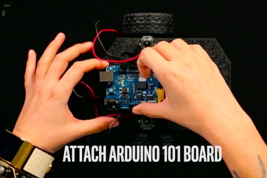
In the meanwhile you can also watch a beginner maker project to learn how to do obstacle avoidance using Arduino 101. Cara Santa Maria is the trainer who’s going to guide you into the tutorial about this really important topic for projects involving moving objects like robots and drones:
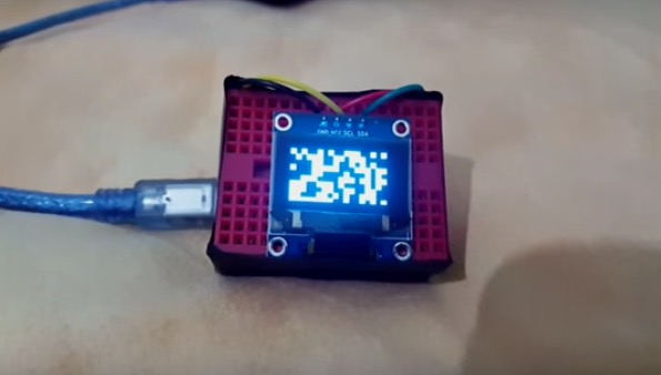
RuntimeProject made a tutorial to create a little cellular automata on a small 126×64 OLED using Arduino Nano.
He worked on one type of cellular automata, the Game of Life by John Conway, which has a grid of cells each having 2 states True or False/on or off/alive or dead. These cells are governed by 2 simple rules:
Rule 1: A cell which is dead and is surrounded by exactly 3 alive cells, will be born
Rule 2: A cell which is alive and has either 3 or 2 alive cells will remain alive, else it dies
The Arduino-based Cellular Automata works using 2 libraries the, Adafruit GFX library to handle all graphics and text displayed on the OLED; Adafruit SSD1306 library which is the driver for the OLED.
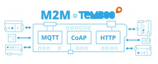
Is there a cool Internet of Things idea that you’ve wanted to try out with your Arduino, but just haven’t had time for? Building a network that integrates multiple sensors and boards into one cohesive application can be time-consuming and difficult. To make it a bit easier, Temboo just introduced new Machine-to-Machine programming that lets you connect Arduino and Genuino boards running locally in a multi-device network to the Internet. Now, you can bring all the power and flexibility of Internet connectivity to Arduino applications without giving up the benefits of using low power, local devices.
Our friends at Temboo now support three M2M communication protocols for Arduino boards: MQTT, CoAP, and HTTP. You can choose which to use based on the needs of your application and, once you’ve made your choice, automatically generate all the code you need to connect your Arduinos to any web service. You can also save the network configurations that you specify, making it easy to add and subtract devices or update their behavior remotely.
With Temboo M2M, you can program flexible distributed device applications in minutes. From monitoring air quality and noise levels in cities to controlling water usage in agricultural settings, networked sensors and devices enable all sorts of powerful IoT applications. You can see it all in action in the video below, which shows how they built an M2M network that monitors and controls different machines working together on a production line.
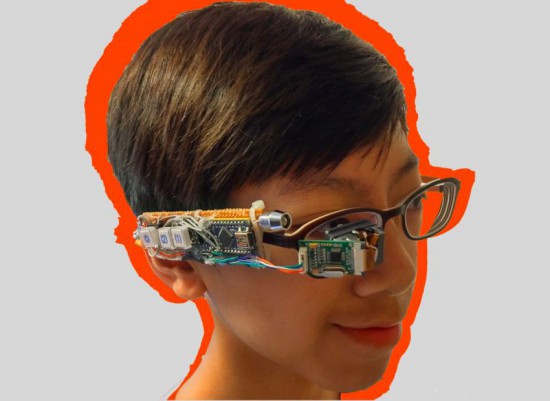
Jordan Fung is a 13-year-old maker and programmer based in Hong Kong. He recently developed Arduino-based smart glasses called Pedosa Glass, which are able to activate, in this first release, a flashlight and a timer:
The Pedosa Glass is powered by a single Arduino Nano running an “operating system” developed by me.
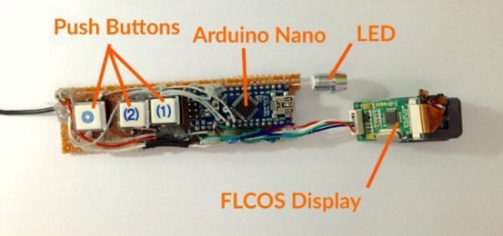
There is a tiny FLCOS display in the front. The AV signal from the Arduino will be displayed on it. It is equipped with 3 push buttons, in which 2 of them are control buttons and one of them be the home button, also equipped with a super-bright white LED for use as a flashlight.
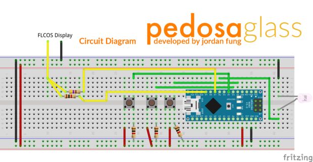
In the picture below you can explore the electronic scheme:
Jordan is working hard to add new applications and features to the project but in the meanwhile he shared his work on a great tutorial on Instructables.
Halloween time is a great moment to explore nice interactive projects and get inspired for installations for other selfie occasions. To spice up the office Donnie Plumly, a creative technologist, decided to make and share with us a molded zombie arm that takes pictures and post them to Twitter.
He used a silicone arm (molded on his own hand ), a custom steel mount to clip to an office partition, and a vibration sensor hooked up to an Arduino Uno. Once the arm is slapped a photo will be taken using an IR Led and passed to the Eye-Fi card in the camera.
The photo is then saved into a Dropbox folder and, using If This Then That (IFTTT), posted to Twitter on the account @ZombieSelfie.
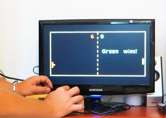
Everyone knows Pong, the first commercially successful arcade video game machine originally release by Atari in 1972. In those years the game helped to establish the video game industry and nowadays is often used by makers to experiment with creating game consoles with Arduino.
Thanks to the VGAx library done by Smaffer, based on the previous work done by Nick Gammon, I have done a little color game for an Arduino Uno working for a VGA monitor. See for details here:
The target was to use an Arduino Uno board without special shields and supporting IC.
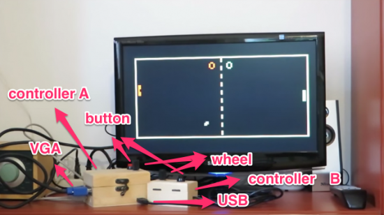
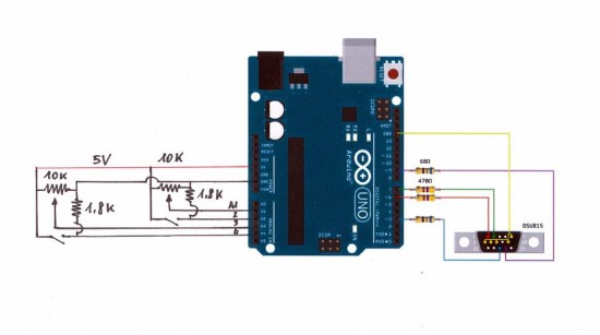
the fundamental components are a button, a potentiometer, few resistors and DSUB15 connector.
Tale a look at the video to see it in action:
Follow the step-by-step guide on Instructables to build one yourself.
There are many ways of remotely-controlling your Arduino or compatible hardware over the Internet. Some are more complex than others, which can be a good thing or a bad thing depending on your level of expertise. Lately we’ve become more interested in this topic and have come across Blynk, which appeared to be a simple solution – and thus the topic of our review.
What is Blynk?
From their website: “Blynk is a Platform with iOS and Android apps to control Arduino, Raspberry Pi and the likes over the Internet. It’s a digital dashboard where you can build a graphic interface for your project by simply dragging and dropping widgets.
It’s really simple to set everything up and you’ll start tinkering in less than 5 mins. Blynk is not tied to some specific board or shield. Instead, it’s supporting hardware of your choice. Whether your Arduino or Raspberry Pi is linked to the Internet over Wi-Fi, Ethernet or this new ESP8266 chip, Blynk will get you online and ready for the Internet Of Your Things.” Here is the original launch video:
Blynk started off as an idea, and raised initial funding through Kickstarter – which was successful and the system has now launched. Blynk comprises of an app on your smartphone (Android or iOS) inside which you can add widgets (controls) to send commands back to your development board (Arduino etc.).
For example, you can add a switch to turn a digital output on or off. Furthermore, data from sensors connected to the development board can be send back to the smartphone. The data passes through the Blynk Cloud server, or you can download and run your own server on your own hardware and infrastructure.
How much does it cost?
Right now (September 2015) the Blynk system is free. We downloaded the app and experimented without charge. We believe that over time there will be payment required for various functions, however you can try it out now to see if Blynk suits your needs then run with it later or experiment with other platforms.
Getting Started
Well enough talk, let’s try Blynk out. Our hardware is an Android smartphone (the awesome new Oppo R7+) for control, and a Freetronics EtherTen connected to our office modem/router:
You can also use other Arduino+Ethernet combinations, such as an Arduino Uno with an Ethernet shield. First you need to download the app for your phone – click here for the links. Then from the same page, download the Arduino library – and install it like you would any other Arduino library.
For our first example, we’ll use an LED connected to digital pin 7 (via a 560 ohm resistor) shown above. Now it’s time to set up the Blynk app. When you run the app for the first time, you need to sign in – so enter an email address and password:
Then click the “+” at the top-right of the display to create a new project, and you should see the following screen:
You can name your project, select the target hardware (Arduino Uno) – then click “E-mail” to send that auth token to yourself – you will need it in a moment. Then click “Create” to enter the main app design screen. Next, press “+” again to get the “Widget Box” menu as shown below, then press “Button”:
This will place a simple button on your screen:
Press the button to open its’ settings menu:
From this screen you can name your button, and also determine whether it will be “momentary” (i.e., only on when you press the button) – or operate as a switch (push on… push off…). Furthermore you need to select which physical Arduino pin the button will control – so press “PIN”, which brings up the scrolling menu as shown below:
We set ours to D7 then pressed “Continue”. Now the app is complete. Now head back to your computer, open the Arduino IDE, and load the “Arduino_Ethernet” sketch included with the library:
Then scroll down to line 30 and enter the auth key that was sent to you via email:
Save then upload the sketch to your Arduino. Now head back to your smartphone, and click the “Play” (looks like a triangle pointing right) button. After a moment the app will connect to the Blynk server… the Arduino will also be connected to the server – and you can press the button on the screen to control the LED.
And that’s it – remote control really is that easy. We’ve run through the process in the following short video:
Data can also travel in the other direction – from your Arduino over the Internet to your smartphone. At the time of writing this (September 2015) you can monitor the status of analogue and digital pins, and widgets can be added in the app to do just that. They can display the value returned from each ADC, which falls between zero and 1023 – and display the values in various forms – for example:
The bandwidth required for this is just under 2 K/s, as you can see from the top of the image above. You can see this in action through the video below:
Conclusion
We have only scratched the surface of what is possible with Blynk – which is an impressive, approachable and usable “Internet of Things” platform. Considering that you can get an inexpensive Android smartphone or tablet for under AU$50, the overall cost of using Blynk is excellent and well worth consideration, even just to test out the “Internet of Things” buzz yourself. So to get started head over to the Blynk site.
A few weeks ago I found a DIODER LED strip set from a long-ago trek to IKEA, and considered that something could be done with it. So in this article you can see how easy it is to control the LEDs using an Arduino or compatible board with ease… opening it up to all sorts of possibilities.
This is not the most original project – however things have been pretty quiet around here, so I thought it was time to share something new with you. Furthermore the DIODER control PCB has changed, so this will be relevant to new purchases. Nevertheless, let’s get on with it.
So what is DIODER anyhow?
As you can see in the image below, the DIODER pack includes four RGB LED units each with nine RGB LEDs per unit. A controller box allows power and colour choice, a distribution box connects between the controller box and the LED strips, and the whole thing is powered by a 12V DC plugpack:
The following is a quick video showing the DIODER in action as devised by IKEA:
Thankfully the plugpack keeps us away from mains voltages, and includes a long detachable cable which connects to the LED strip distribution box. The first thought was to investigate the controller, and you can open it with a standard screwdriver. Carefully pry away the long-side, as two clips on each side hold it together…
… which reveals the PCB. Nothing too exciting here – you can see the potentiometer used for changing the lighting effects, power and range buttons and so on:
Our DIODER has the updated PCB with the Chinese market microcontroller. If you have an older DIODER with a Microchip PIC – you can reprogram it yourself.
The following three MOSFETs are used to control the current to each of the red, green and blue LED circuits. These will be the key to controlling the DIODER’s strips – but are way too small for me to solder to. The original plan was to have an Arduino’s PWM outputs tap into the MOSFET’s gates – but instead I will use external MOSFETs.
So what’s a MOSFET?
In the past you may have used a transistor to switch higher current from an Arduino, however a MOSFET is a better solution for this function. The can control large voltages and high currents without any effort. We will use N-channel MOSFETs, which have three pins – Source, Drain and Gate. When the Gate is HIGH, current will flow into the Drain and out of the Source:
A simplistic explanation is that it can be used like a button – and when wiring your own N-MOSFET a 10k resistor should be used between Gate and Drain to keep the Gate low when the Arduino output is set to LOW (just like de-bouncing a button). To learn more about MOSFETS – get yourself a copy of “The Art of Electronics“. It is worth every cent.
However being somewhat time poor (lazy?), I have instead used a Freetronics NDrive Shield for Arduino – which contains six N-MOSFETs all on one convenient shield – with each MOSFET’s Gate pin connected to an Arduino PWM output.
So let’s head back to the LED strips for a moment, in order to determine how the LEDs are wired in the strip. Thanks to the manufacturer – the PCB has the markings as shown below:
They’re 12V LEDs in a common-anode configuration. How much current do they draw? Depends on how many strips you have connected together…
For the curious I measured each colour at each length, with the results in the following table:
So all four strips turned on, with all colours on – the strips will draw around 165 mA of current at 12V. Those blue LEDs are certainly thirsty.
Moving on, the next step is to connect the strips to the MOSFET shield. This is easy thanks to the cable included in the DIODER pack, just chop the white connector off as shown below:
By connecting an LED strip to the other end of the cable you can then determine which wire is common, and which are the cathodes for red, green and blue.
The plugpack included with the DIODER pack can be used to power the entire project, so you will need cut the DC plug (the plug that connects into the DIODER’s distribution box) off the lead, and use a multimeter to determine which wire is negative, and which is positive.
Connect the negative wire to the GND terminal on the shield, and the positive wire to the Vin terminal. Then…
the red LED wire to the D3 terminal,
the green LED wire to the D9 terminal,
and the blue LED wire to the D10 terminal.
Finally, connect the 12V LED wire (anode) into the Vin terminal. Now double-check your wiring. Then check it again.
Testing
Now to run a test sketch to show the LED strip can easily be controlled. We’ll turn each colour on and off using PWM (Pulse-Width Modulation) – a neat way to control the brightness of each colour. The following sketch will pulse each colour in turn, and there’s also a blink function you can use.
// Controlling IKEA DIODER LED strips with Arduino and Freetronics NDRIVE N-MOSFET shield
// CC by-sa-nc John Boxall 2015 - tronixstuff.com
// Components from tronixlabs.com

#define red 3
#define green 9
#define blue 10
#define delaya 2

void setup()
{
  pinMode(red, OUTPUT);
  pinMode(green, OUTPUT);
  pinMode(blue, OUTPUT);
}

void blinkRGB()
{
  digitalWrite(red, HIGH);
  delay(1000);
  digitalWrite(red, LOW);
  digitalWrite(green, HIGH);
  delay(1000);
  digitalWrite(green, LOW);
  digitalWrite(blue, HIGH);
  delay(1000);
  digitalWrite(blue, LOW);
}

void pulseRed()
{
  for (int i=0; i<256; i++)
  {
    analogWrite(red,i);
    delay(delaya);
  }
  for (int i=255; i>=0; --i)
  {
    analogWrite(red,i);
    delay(delaya);
  }
}

void pulseGreen()
{
  for (int i=0; i<256; i++)
  {
    analogWrite(green,i);
    delay(delaya);
  }
  for (int i=255; i>=0; --i)
  {
    analogWrite(green,i);
    delay(delaya);
  }
}

void pulseBlue()
{
  for (int i=0; i<256; i++)
  {
    analogWrite(blue,i);
    delay(delaya);
  }
  for (int i=255; i>=0; --i)
  {
    analogWrite(blue,i);
    delay(delaya);
  }
}

void loop()
{
  pulseRed();
  pulseGreen();
  pulseBlue();
}
As always, there’s a better way of doing things and one example of LED control is the awesome FASTLED library by Daniel Garcia and others. Go and download it now – https://github.com/FastLED/FastLED. Apart from our simple LEDS, the FASTLED library is also great with WS2812B/Adafruit NeoPixels and others.
One excellent demonstration included with the library is the AnalogOutput sketch, which I have supplied below to work with our example hardware:
#include <FastLED.h>

// Example showing how to use FastLED color functions
// even when you're NOT using a "pixel-addressible" smart LED strip.
//
// This example is designed to control an "analog" RGB LED strip
// (or a single RGB LED) being driven by Arduino PWM output pins.
// So this code never calls FastLED.addLEDs() or FastLED.show().
//
// This example illustrates one way you can use just the portions
// of FastLED that you need.  In this case, this code uses just the
// fast HSV color conversion code.
//
// In this example, the RGB values are output on three separate
// 'analog' PWM pins, one for red, one for green, and one for blue.

#define REDPIN   3
#define GREENPIN 9
#define BLUEPIN  10

// showAnalogRGB: this is like FastLED.show(), but outputs on
// analog PWM output pins instead of sending data to an intelligent,
// pixel-addressable LED strip.
//
// This function takes the incoming RGB values and outputs the values
// on three analog PWM output pins to the r, g, and b values respectively.
void showAnalogRGB( const CRGB& rgb)
{
  analogWrite(REDPIN,   rgb.r );
  analogWrite(GREENPIN, rgb.g );
  analogWrite(BLUEPIN,  rgb.b );
}


// colorBars: flashes Red, then Green, then Blue, then Black.
// Helpful for diagnosing if you've mis-wired which is which.
void colorBars()
{
  showAnalogRGB( CRGB::Red );   delay(500);
  showAnalogRGB( CRGB::Green ); delay(500);
  showAnalogRGB( CRGB::Blue );  delay(500);
  showAnalogRGB( CRGB::Black ); delay(500);
}

void loop()
{
  static uint8_t hue;
  hue = hue + 1;
  // Use FastLED automatic HSV->RGB conversion
  showAnalogRGB( CHSV( hue, 255, 255) );

  delay(20);
}


void setup() {
  pinMode(REDPIN,   OUTPUT);
  pinMode(GREENPIN, OUTPUT);
  pinMode(BLUEPIN,  OUTPUT);

  // Flash the "hello" color sequence: R, G, B, black.
  colorBars();
}
You can see this in action through the following video:
So if you have some IKEA LED strips, or anything else that requires more current than an Arduino’s output pin can offer – you can use MOSFETs to take over the current control and have fun. And finally a plug for my own store – tronixlabs.com – offering a growing range and Australia’s best value for supported hobbyist electronics from adafruit, DFRobot, Freetronics, Seeed Studio and much much more.
As always, have fun and keep checking into tronixstuff.com. Why not follow things on twitter, Google+, subscribe for email updates or RSS using the links on the right-hand column, or join our forum – dedicated to the projects and related items on this website.
Planet Arduino is, or at the moment is wishing to become, an aggregation of public weblogs from around the world written by people who develop, play, think on Arduino platform and his son. The opinions expressed in those weblogs and hence this aggregation are those of the original authors. Entries on this page are owned by their authors. We do not edit, endorse or vouch for the contents of individual posts. For more information about Arduino please visit www.arduino.cc
You are currently browsing the archives for the tutorial category.