Posts | Comments

Planet Arduino

Archive for the ‘Arduino Tutorial’ Category

This is part of a series titled “Getting Started with Arduino!” by John Boxall – A tutorial on the Arduino universe. The first chapter is here, the complete series is detailed here.

Welcome back fellow arduidans!

This chapter we will examine piezo buzzers, continue with our alarm clock, and then spend more time with the wireless radio modules by creating some remote control systems and sending various data over the airwaves. So let’s go!

Sometimes you would like to make some noise. For warnings, fun, or to annoy people. A very simple and inexpensive way to do this is with a piezoelectric buzzer. In simple terms, it contains a disc of metal that can deform when a current is applied to it. If you apply an alternating current at a high enough frequency, the disc will move fast enough to create a sound wave, something we can hear.

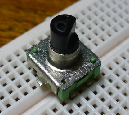
This is an example of a small piezo buzzer:

bzzzzz

This example was very cheap, less than $2.  Here is the data sheet: PS1240.pdf. It can run from between 3 and 30 volts AC – which thankfully the output from our Arduino falls between. But how do you output AC from an Arduino? There are several ways, however the easiest is using pulse-width modulation (PWM). If you look at your Arduino’s digital output sockets, some are labelled PWM. Using the function analogWrite(); you can send a PWM signal to the buzzer. For example:

/*
Example 13.0
Drive a piezoelectric buzzer with Arduino
http://tronixstuff.wordpress.com/tutorials > Chapter 13
*/
void setup()
{
     pinMode(11, OUTPUT);   // sets the pin as output
}
void loop()
{
     analogWrite(11,128);
     delay(500);
     digitalWrite(11, LOW);
     delay(500);
}

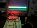
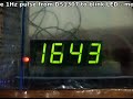
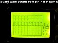
The sketch above will beep the piezo on and off, and be somewhat annoying. Perfect. However with the analogWrite(); function it is impossible to use the full frequency range of the piezo buzzer. With a value of 254 for the duty cycle, the frequency generated is around 1500 Hz:

Later on we will explore ways to create a better range of sounds. But now to use that buzzer in our alarm clock to help wake people up.

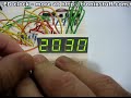
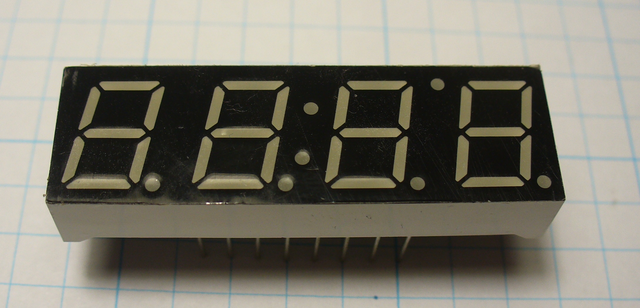
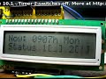
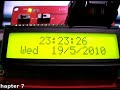
Continuing on from exercise 12.1, this chapter we will add some more features to the clock. First of all is the piezo buzzer. As we just discussed above, using it is quite simple. On the hardware side of things, we can replace the resistor and LED connected between digital pin 6 and ground with our piezo buzzer. On the software side of things, instead of digitalWrite(6, HIGH); we use analogWrite(6,128);. Very easy. And here is a short video – with sound!

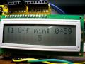
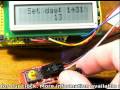
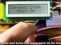
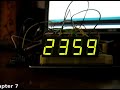
Moving on, it’s time to clean up the alarm function in general. Most alarm clocks have a snooze function, so let’s add one as well. When the alarm sounds, the user presses button four to turn off the buzzer, and is then asked if they want to snooze. Button one is yes and four is no. If yes, add ten minutes to the alarm time and carry on as normal. When adding the ten minutes be sure to check for increasing the hour as well, and also take into account the jump from 2359h to 0000h (or 2400h). If the user presses no, the alarm is switched off and the user warned with the flashing “OFF”.

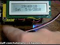
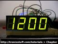
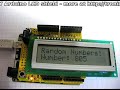
Example 13.1 – Here is a demonstration of what I came up with:

and the accompanying sketch: example13p1.pdf. The hardware is the same as exercise 12.1, except the LED and resistor from digital pin 6 to GND has been replaced by the piezo buzzer as described earlier. You will find the snooze function is controlled in the checkalarm(); function in the sketch.

In chapter eleven we started to examine the inexpensive serial data transmitter/receiver pairs. In this chapter we will continue working with them, to create the backbone of various remote control and data transmission ideas for you to use.

Example 13.2

First of all, a simple remote control with four channels. That is, it has four buttons, and the transmitter will send out the state of the four buttons, high or low. This would be useful for a remote control toy or a perhaps robot. The sketches are quite simple. The transmitter reads the buttons with digitalRead(); then transmits a single letter a~h – which is code for a button and its state. For example, a means button 1 is low, h means button 4 is high. The receiver just decodes that a~h code and sends the result to the serial monitor window. Here is the sketch for the transmitter – tx.pdf and receiver – rx.pdf.

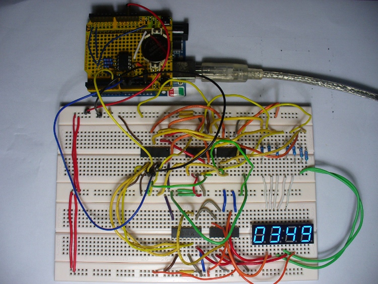
To save time I will use the button board created in example 12.3. Here are the schematics for the transmitter and receiver sections:
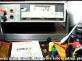
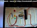
And set up:

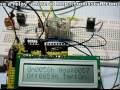
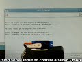
And finally a video of the serial monitor showing the button states:

Now that we have the data being sent across, let’s get some switching happening.

Example 13.3

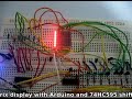
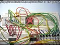
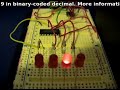
Using the same transmitter system as example 13.2, we will turn on or off four LEDs at the receiving end. Of course you could use relays, transistors, 74HC4066s, etc instead. Our sketch (ex13.3rx.pdf) decodes the transmitted data once more, but sets the digital pins high or low depending on the received code. Here is the schematic for the new receiver:

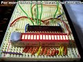
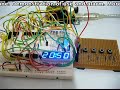
… and the board laid out:

And again a quick demonstration video:

Now that you can turn the LEDs on or off with a push of a button, there are a few other ways of controlling those digital outputs with the remote control rig without altering the hardware.

Example 13.4

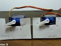
This time, we will control two digital outputs with the four buttons, as each output will have an on and off button. Consider this sketch; and the following demonstration video:

So there you have various ways to control digital outputs and send basic data across a wireless radio serial data link. In the coming chapters we will examine sending more detailed data, such a numbers, and more complex variables using a faster and more reliable hardware link.

Well that is another chapter over. However, as usual I’m already excited about writing the next instalment… Congratulations to all those who took part and built something useful!

Please subscribe (see the top right of this page) to receive notifications of new articles. High resolution photos are available from flickr.

If you have any questions at all please leave a comment (below). We also have a Google Group dedicated to the projects and related items on the website – please sign up, it’s free and we can all learn something. If you would like to showcase your work from this article, email a picture or a link to john at tronixstuff dot com. You might even win a prize!

Don’t forget to check out the range of gear at Little Bird Electronics!

So have fun, stay safe and see you soon for our next instalment, hopefully by 7th August 2010.

Hello readers

Today we are going to examine the Texas Instruments TLC5940 16-channel LED driver IC. My reason for doing this is to demonstrate another, easier way of driving many LEDs as well as LED display modules that are common-anode. If you have a common-cathode display module, you should have a look at the Maxim MAX7219. Moving along, here is the IC:

Another nice big DIP IC. Also available in HTSSOP and QFN packaging. What can this IC do for us? It can control 16 LEDs per IC, and also be cascaded to control more and more, with the display data arriving via a serial line in the same manner as a 74HC595 shift register. Furthermore, another benefit of this IC is that you don’t need matching current-limiting resistors for your LEDs, as this IC is a current sink, in that the current flows from the 5V rail, through the LED, then into the IC. However, it can control the brightness of the LEDs using pulse-width modulation over 4096 steps via software, or using a single resistor.

What is pulse-width modulation? Normally an LED might be on, or off. But if you switch it on and off very quickly, it does not look as bright (as it is not on 100% of the time). If you alter the period of time between on and off, you can alter the perceived brightness of the LED. Here is an example, compare the brightness of the LED bars against the display of the CRO – as the brightness increases, the voltage (amplitude [vertical thickness]) spreads across the entire time period (horizontal axis); as the brightness decreases, the voltage spread across time retreats:

Using the IC is very easy on the hardware front. Here is the data sheet: TLC5940.pdf. The pinout diagram is quite self-explanatory:

Pins OUT0~OUT15 are the current-sink pins for each LED. When one is selected they allow current to flow into the IC from the 5V rail, with the LED in between – turning it on. However it is easier to understand with a practical example, such as this (click to enlarge):

Here we have our Arduino board or compatible sending serial data to the TLC5940 to control sixteen LEDs. The 2k ohm resistor is required to set the maximum current available to flow through the LEDs, thereby adjusting their brightness. Using software you can adjust the brightness with PWM for each LED by itself. Very important: this circuit will need external power into the Arduino or a separate 5V power supply. The circuitry on the breadboard draws up to ~318 mA by itself – running the Arduino from USB only made it somewhat flaky in operation. Here is the circuit in action with an ammeter between the breadboard and 5V out on the Arduino:

Anyhow, let’s get moving once more – here is the assembled demonstration circuit:

For our example, we will be using the Arduino way of doing things. Thankfully (once more) there is a library to make controlling the IC exponentially easier. The library page and download files are available from here; the documentation page is here.  If you need guidance on installing a library, please visit here. However the commands to control the IC are quite simple with the Arduino library.

First of all, include the TLC5940 library, as such:

#include “Tlc5940.h”

Then in void setup(); you create the object using the function:

Tlc.init();

You can insert a number between 0 and 4095 to set the starting PWM (LED brightness) value, however this is optional.

Setting an output for display requires two functions, first Tlc.set(l, p); where l is the output (0~15) and p is the PWM brightness level – then execute Tlc.update(); which sends the command to the IC to be executed. The sketch below is easy to follow and understand the process involved.

Moving forward with the demonstration, here is the sketch  – TLC5940demo.pdf, and the video clip of operation:

When the LEDs are glowing from dim to bright and return, we are altering the PWM value of the LEDs to adjust their brightness. This also occurs during the last operation where the LEDs are operating like the bonnet of KITT.

Well once again that’s enough blinkiness for now, again this is another useful IC that helps simplify things and be creative. As always, avoid the risk of counterfeit ICs  – so please avoid disappointment, support your local teams and buy from a reputable distributor. Living in Australia, mine came from Farnell (part number 1226306). So have fun!

Remember, if you have any questions at all please leave a comment (below). We also have a Google Group dedicated to the projects and related items on the website – please sign up, it’s free and we can all learn something. High resolution photos are available from flickr.

Otherwise, have fun, stay safe, be good to each other – and make something! :)

[Note – the TLC5940 was purchased by myself personally and reviewed without notifying the manufacturer or retailer]

Hello readers

Today we are going to examine the 74HC238 decoder/demultiplexer IC. My reason for writing this was to examine another way to get more output pins when using an Arduino or compatible board. However you can use any combination of three logic lines to turn on or off eight mutually exclusive outputs. How? Let’s find out…

First of all, here is the IC:

It is also available in SO16, SSOP16,  TSSOP16 and DHVQFN16 packages. What? Here is a good list of various SMD packaging types. Although my sample is from NXP, a quick search shows it is also made by Texas Instruments and ST Microelectronics. Here is the NXP data sheet.

The pin layout is very simple, apart from +5V and ground, you have six pins that control the outputs, and eight output pins, however in reality you only need to control three from the microcontroller or other logic lines. Here is the pinout diagram:

To get the output pins high, you use a combination of levels on pins A0~A2 and possibly E3. If you leave E3 low, no outputs can be set to high. The input combination required for each output is described in this table from the data sheet (click to enlarge):

Notice that columns with an X can be set either high or low, but you must not leave them floating, so always connect or set an X to high or low. If you need to have active low outputs (that is, outputs are high instead of low), there is the 74HC138. So now to do this in real life! Here is a demonstration schematic to use the 74HC238 with an Arduino Duemilanove or 100% compatible board:


… and in real life:

And here is a demonstration video, using this arduino sketch: 74HC238Arduino.pdf

Question: In real life, in which country is the Hoff a popular singer?

As with most other ICs of this type, you can only source 25 milliamps of current from each output, so if you need more you will have to consider the use of a switching NPN transistor etc. Although only one output can be high at a time, if you scan them quick enough, you can create the illusion that all are on at once (as in the video). Apart from LEDs and other items, you could use this IC to control stepper motors or even create a safeworking environment on a model train layout.

To conclude, the 74HC238 offers one of several ways to control more things with less control pins. Ideal for mutually exclusive outputs, however if you needed more than one high at once, the 74HC595 shift register would be the better solution. (See here for a 74HC595 tutorial).

As always, avoid the risk of counterfeit ICs and get yours from a reputable distributor. Living in Australia, mine came from Little Bird Electronics.

Once again, thank you for reading and I look forward to your comments and so on. Furthermore, don’t be shy in pointing out errors or places that could use improvement. Please subscribe using one of the methods at the top-right of this web page to receive updates on new posts. Or join our new Google Group. High resolution photos are available on flickr.

Otherwise, have fun, be good to each other – and make something! :)

This is part of a series titled “Getting Started with Arduino!” by John Boxall – A tutorial on the Arduino universe. The first chapter is here, the complete series is detailed here.

Welcome back fellow arduidans!

This chapter we will spend some more time with the rotary encoder by using it to control a clock, look at ways of driving a common-anode LED display with Arduino, and make a usable alarm clock with which we can start to move from the prototype stage to an actual finished product – something you would be proud to give to someone.

So off we go…

In chapter eleven, we looked at getting some values from the rotary encoder. Not the easiest way of receiving user input, but certainly interesting. This week I have an example for you where the encoder is used for setting the time of a digital clock.

Example 12.1

This example is basically two previous projects mashed together. It consists of the LED digital clock from exercise 7.1, and the rotary encoder sketch from example 11.2. The sketch was quite simple in theory, but somewhat complex in execution. The idea was to read the decoder, and after every read, display the time. However, if the encoder’s button was pressed, the time set function would be activated. At this point, you turn the encoder in one direction to set the hours, and the other direction to set the minutes. Then press the button again to set that time and return to normal operations.

To recreate it you will need:

  • Your standard Arduino setup (computer, cable, Duemilanove or 100% compatible)
  • Seven 560 ohm 1/4 watt resistors
  • Four 1 kilo ohm 1/4 resistors
  • Four BC548 NPN transistors (if you cannot find these, you can use 2N3904)
  • Two 74HC595 shift registers
  • DS1307 timer IC circuit components (see this schematic from chapter seven) or a pre-built module
  • Solderless breadboard and connecting wires

Here is the sketch for your perusal: example 12.1.pdf, and the matching schematic (sorry, I forgot to add the DS1307 module – see example 12.2 schematic below for how to do this):

… in real life:

and a video clip:

After watching that clip you can soon see that there is an issue with the encoder. As a normal switch can bounce (turn on and off very very quickly in the latter part of operation), so can a rotary encoder. That is why it would sometimes return a result of clockwise, instead of anti-clockwise. Furthermore, they are right little pains when trying to use in a breadboard, so if you were going to use one in greater lengths, it would pay to make up your own little breakout board for it. Therefore at this stage we will leave the encoder for a while.

You may also have noticed the extra shield between the real time clock shield (yellow) and the TwentyTen arduino board. It is the Screwshield for Arduino – reviewed here. It is very useful to making a stronger connection to the I/O pins, or using normal multi-core wires.

Next on the agenda is the common-anode LED display. Normally the LED display we have demonstrated in the past has been common-cathode, and very easy to use. Current would flow from the power supply, through the shift register’s outputs (for example the 74HC595), through current-limiting resistors, into the LED segment, then off to earth via the cathode. Current flows through a diode from the anode to the cathode, and finally back to earth/ground. For a refresher on diodes, please read this article.

The other month I found this useful LED display:

Absolutely perfect for our clock experimentations. A nice colon in the middle, and another LED between the third and fourth digit which could make a good indicator of some sort. However the one catch (always a catch…) is that is was common-anode. This means that current starts from the power supply, through the common anode pin for the particular digit, then the LED segment, the LED’s individual cathode pin, through the current-limiting resistor and then to ground. With the current flowing in the opposite direction via a common anode, we can’t just hook the display up to our 74HC595 shift register.

Therefore, we will need the shift register to control switches to allow the current to flow through each segment, just like we have done previously controlling the cathodes of a common cathode display (see example 12.1). So to control the digits of this new display, we will need twelve switches (eight for the segments of the digit, and four to control the anodes). That would mean twelve BC548  transistors and 10k ohm resistors, and a lot of mess.

Example 12.2

Instead we will now use the 74HC4066 quad bilateral switch IC. I have reviewed this chip being used with Arduinos in a separate article here. The 74HC4066 is quite a common chip, available from many suppliers including: Farnell/Newark (part number 380957), Digikey (part number 568-1463-5-ND) or Mouser (771-74HC4066N). If you cannot find them, email me and I can sell you some at cost plus postage. Once you have a understanding of this IC, please consider the following circuit:


Most of this should be easily understood. One shift register is controlling the anodes, turning them on and off via a 74HC4066. In past examples this shift register would have turned off common cathodes via a 10k resistor and an NPN transistor. The other shift register is controlling the individual LEDs for each digit via a pair of 74HC4066s (as they only have four switches per IC).

Here is the sketch, this should be quite a familiar piece of code for you by now: example 12.2.pdf.

To recreate it you will need:

  • Your standard Arduino setup (computer, cable, Duemilanove or 100% compatible)
  • Seven 560 ohm 1/4 watt resistors
  • DS1307 timer IC circuit components (see this schematic from chapter seven) or a pre-built module
  • Two 74HC595 shift registers
  • Three 74HC4066 quad bilateral switch ICs
  • Solderless breadboard and connecting wires
  • LED clock display module

And here is the result, with red and a blue display.

And the usual board layout:

QuestionDo you think the time shown on the display was correct when I took the photo? :) Personally the blue looks really good in a dark background. You can also get them in yellow and green.

Moving along. Now and again, you often want to have a few buttons in use for user input, however the cheap ones don’t really like to sit in a breadboard. Naturally, you could make your own “button shield”, which would be very admirable, but then it would be preset to certain pins, which could interfere with your project. I had the same problem in writing this chapter, so came up with this example of an external “button panel” to make life easier.

Example 12.3

Here is the schematic, nothing complex at all – just four buttons and the required 10k ohm pull-down resistors:

and the finished product:

This was a quick job, as I will need to use a few buttons in the near future. Have also put some rubber feet on the bottom to stop the solder joints scratching the surface of the bench. Originally I was going to chop off the excess board at the top, but instead will add some LEDs to it after finishing this article. However using this button board will save a lot of frustration by not trying to jam the buttons into a breadboard.

Exercise 12.1

Now it is time for you to do some work. From this chapter onwards, we will be working on making a small alarm clock – something you could use. Just like the six million dollar man, we have the capability, the technology, and so on … except for Steve Austin. So this chapter, your task is to create and breadboard the  circuit and the underlying sketch. Using the LED display from example 12.1, your clock will have a menu option to set the time, alarm time, turn on and off the alarm, a snooze button – and also switch the display on and off (so you don’t stare at it when you should be trying to sleep).

You could either use a DS1307 module, or the raw parts. For an explanation of the circuitry, please see this post about making a RTC shield. You can always change it when we get to making a real prototype. The same with the Arduino – but for this exercise just stick with the normal board. Later on we will use a bare circuit the same as in chapter ten. With regards to user input, it’s up to you. A rotary encoder could be a real PITA, my example below just uses buttons. Anyhow, off you go!

Parts you will need:

  • Your standard Arduino setup (computer, cable, Duemilanove or 100% compatible)
  • Seven 560 ohm 1/4 watt resistors
  • DS1307 timer IC circuit components (see this schematic from chapter seven) or a pre-built module
  • Two 74HC595 shift registers
  • Three 74HC4066 quad bilateral switch ICs
  • Four normally open buttons or a board as described in example 12.3
  • Solderless breadboard and connecting wires
  • LED clock display module

Here is my interpretation of the answer to the exercise, the sketch: exercise 12.1.pdf. Although this is a particularly long sketch for our examples, it is broken up into many functions which are quite modular, so you can easily follow the flow of the sketch if you start at void loop(). All of the types of functions used have been covered in the past tutorials. In then next chapters we will add more functions, such an an adjustable snooze, selectable blinking colon, and so on. If you have any questions, please ask.

The buttons have several functions. In normal clock display mode, button one is for menu, two turns the alarm on, three turns it off, and four turns the display on and off. If you press menu, button two is to select time set, three for alarm set, and four is like an enter button. When in the time/alarm set modes, button one increases the hour, button two increases minutes in units of ten, and button three increases minutes in ones, and four is enter. When the alarm activates, button four turns it off.

The schematic is just example 12.2 and example 12.3 connected together, however the first button on the external board is connected to digital pin 8 instead of 1.

So here is a photo of our work in progress:

And a video clip showing the various functions of the clock in operation:


Well that is another chapter over. However, as usual I’m already excited about writing the next instalment… Congratulations to all those who took part and built something useful!

Please subscribe (see the top right of this page) to receive notifications of new articles. High resolution photos are available from flickr.

If you have any questions at all please leave a comment (below). We also have a Google Group dedicated to the projects and related items on the website – please sign up, it’s free and we can all learn something. If you would like to showcase your work from this article, email a picture or a link to john at tronixstuff dot com. You might even win a prize!

Don’t forget to check out the range of gear at Little Bird Electronics!

So have fun, stay safe and see you soon for our next instalment, hopefully by 23rd July 2010.

This is part of a series titled “Getting Started with Arduino!” by John Boxall – A tutorial on the Arduino universe. The first chapter is here

Welcome back fellow arduidans!

Finally it is wireless week here in the tiny tronixstuff lab, as we will start to investigate radio data transmission; then followed by starting to make sense of rotary encoders.

So let’s go!

As technology has marched along and generally improved on the past, things have been getting small and relatively cheaper. What was once jaw-droppingly amazing is now just meh. But as you are reading this, you know differently. We can now take control of this technology for our own devices. What has been in the past quite unapproachable is now relatively – the concept of wireless data transmission. But no just sending a signal, like a remote-control garage door opener – but sending actual,  useful data – numbers and characters and so on.

How is it so? With this pair of tiny devices:

Quite small indeed – the pins are spaced 2.54mm apart, and the graph paper is 5mm square. The transmitter is on the right. This pair operates at 315 kHz, over up to a theoretical 150 metres. The data transmission speed is 2400 bps (bits per second). These units are serial passthrough, that is they can replace a link of wire between the serial TX (pin 1) from one Arduino, and the RX of another Arduino (pin 0). They don’t need aerials for very short distances, but the use of one will extend the range towards the maximum. And finally, the transmitter needs between 2 and 10 volts; the receiver 5. Here is the data sheet for these modules: 315MHz.pdf. Normally they are sold individually, for example the transmitter and receiver. You can also find faster (data speed) modules, however we will use these ones today.

In preparation to use these modules, another library needs to be installed – the VirtualWire library. Download the latest revision from the following location: http://www.open.com.au/mikem/arduino/.

There is also a guide to using the library in .pdf format as well. Please note the library author’s instructions with regards to licensing on the last page of the guide. For a refresher on how to install a library, please head back to chapter two. This library will save us a lot of time, it takes care of checking for errors, and only allows complete, correct data (i.e. what is received matches what is sent) to be used in the receiver’s sketch. However, as wireless is not 100% reliable, you need to take into account that transmissions may not be received, or erroneous ones will be ignored by the receiver’s sketch. You can reduce the data speed to improve reliability and range.

Therefore if you are using this for some important communications, have the transmitter repeatedly sent the message. Later on in this series we will investigate more powerful solutions. Anyhow, moving along …

Example 11.1

First of all, we will demonstrate the use of these modules with a basic sketch. It sends some text from one Arduino to another. The receiving Arduino sends the data to the serial monitor box. Of course you could always use an LCD module instead. In my own inimitable style the sketches are very simple, yet allow you to use their contents in your own work. Here is the sketch for the transmitter – tx.pdf and the receiver – rx.pdf.

When working with two sketches at the same time, you can have two Arduinos connected to your PC simultaneously,  just remember to select the correct USB port for the correct Arduino. Do this with the tools > serial port menu option in the IDE. Otherwise you will become very frustrated if you upload the rx sketch to the tx Arduino. :) Furthermore, you will need to remove the wire from digital 0 to the data pin on the receiving units before uploading the sketch. And finally, remember to set the serial monitor window at 9600 baud. Now I can laugh, but earlier I kept setting it to 2400 as that number was in my mind from the sketch.

Here are my two boards in action:

Although having both boards connected to the one computer is only useful for demonstration purposes, in real life this is obviously useless. Remember that once you upload your sketch the Arduino doesn’t need a computer, only a power supply. You can feed yours between 7 and 12 volts DC through the socket. A nice switchmode power pack will do nicely, or if you are a cheapskate like me, a PP3 battery and clip soldered to a DC plug:

You may find that when you use a battery powered Arduino that it basically does not work. Arduino genius Jon Oxer (co-author of Practical Arduino) has found a solution for this issue – place a 10k resistor between GND and digital 0 (RX), or between digital pins 0 and 1. The next thing to consider it improving the reception range. This can be done using two methods – the first by connecting an external antenna, either a length of wire, or perhaps a purpose-built aerial. The second method is to increase the supply voltage of the transmitter up to 12 volts.

Now it is your time to do some work:

Exercise 11.1

You now are able to send characters using the radio link from one Arduino to another. Now it is time to control things remotely. For the purpose of the exercise, we will just control three LEDs, turning them on and off. You already know how to control other things with digital output pins, so we just need to focus on getting the switching on and off. Hint – you can send characters via the wireless link, so create your own codes.

You will need:

Here is the schematic of my interpretation:


… the transmitter:

… the receiver:

and the video:

So how did you go? Hopefully this exercise was easier than you had first expected. If not, here are the example sketches: exercise 11.1 tx.pdf and exercise 11.1 rx.pdf. A basic transmit/receive system like this would also be handy for testing the range that wireless modules can operate over, or testing a particular site to see if you could implement such wireless modules. It’s always better to test before agreeing to make something for someone.

If you are having trouble understanding the sketches, please feel free to ask for help via email, leaving a comment, or asking the question in our Google Group.

That concludes our work with radio wireless links – for now.

Next on the agenda is the rotary encoder. Recall how we used a potentiometer in the previous chapters as a dial, to select menu options using the readdial() function. It was simple, cheap and it worked, but some may say it was a kludge. There must be a better way! And there is, with the rotary encoder. A rotary encoder looks like a potentiometer, but it is a knob that can be rotated in either direction infinitely. Furthermore, the knob is also a normally-open button. The encoder we will be using in this chapter is a 12-step encoder, in that you can feel it physically resist rotation slightly twelve times over the 360 degrees of rotation.

Here is our example:

On one side there are three pins, and two on the opposing side. On the perpendicular sides are legs for strength, that is they are meant to be soldered into a PCB to lock it in nicely. The problem for us is that those legs interfere when trying to use the encoder in a breadboard, so I have bent them up and cut them off:

The pins are easy to understand. The two pins on one side are the button contacts, just like any simple button. The other side with the three pins – the centre goes to ground, and the outside pins are the forwards and backwards output pins. The data sheet for our encoder is here. After fooling about with this all afternoon, the quickest way to get a feel for how it works is with a simple demonstration. So first we will test it out, then see how we can use it in our user-interfaces.

Example 11.2

This example is very easy to assemble. You only need an encoder, and the usual Arduino setup. Here is the sketch: example 11.2.pdf; and the schematic:

and in real life:

and finally a snapshot of the output. Don’t forget to set the speed in your serial monitor box to 115200 baud:

So as you can see, this is a much better solution that then potentiometer that we used in the past. Plus having the button integrated in the encoder is very convenient, you can really create a user interface with only one control. In the next instalment of this series we will implement the encoder in an existing design.

At this point I would like to ask you for some feedback. Would you like shorter, weekly articles – or longer, fortnightly (every two weeks) articles? Please leave a comment with your opinion.

Subscribe (see the top right of this page) to receive notifications of new articles. High resolution photos are available from flickr.

If you have any questions at all please leave a comment (below). We also have a Google Group dedicated to the projects and related items on the website – please sign up, it’s free and we can all learn something. If you would like to showcase your work from this article, email a picture or a link to john at tronixstuff dot com. You might even win a prize!

Don’t forget to check out the range of gear at Little Bird Electronics!

So have fun, stay safe and see you soon for our next instalment! (Hopefully the 10th of July) :)


This is part of a series titled “Getting Started with Arduino!” by John Boxall – A tutorial on the Arduino universe.

The first chapter is here.

Welcome back fellow arduidans!

This week we will minimise an Arduino Duemilanove board, use time to control, and then mix all of that up. The hardware, not the readers… :)

So let’s go!

As time goes by, you will want to build projects to use away from the bench, or that are permanent. Although doing so is infinitely fun, it can become expensive if you keep buying Arduino boards for each project or proof-of-concept prototype, or even finished products. However, as always, the Arduino team have solved this problem for us as well. The actual microcontroller integrated circuit (e.g. ATmega328P-PU) can operate with a lot less circuitry than that is contained on your Duemilanove or compatible board. In fact, you can have a functioning Arduino system with three components and a 5V power supply.

How?

To start, please download the Duemilanove schematic from here. Upon glancing at it for the first time, there seems to be a lot of things required. However if you just want to use the digital and analogue pins, you can cut that schematic down to a lot less, however you need to make a couple of changes to how you upload the sketch. Here is what you can get away with:

X1 is the 16 MHz resonator. Using only the main circuit on the left, to upload your sketch you need to place the ATmega chip in your Arduino board, upload the sketch, then very carefully remove the chip and place it into your circuit, breadboard, etc. Please make sure to observe anti-static precautions, and always use a chip puller (below).

Furthermore, if you only have one chip, it would be very wise to have a second or third as a backup. A programmed ATmega with the Arduino bootloader can be had for less than US$6. Below is a shot of my barebones Arduino system at work. It is setup to run this basic example: example 10.1.pdf

The blue and yellow wires run off to a 5 volt power supply. And here is it working:

To recreate this at home, you will need:

A note about the resonator. Your Arduino board will most likely have a metal crystal, however a resonator is a little cheaper and easier to use, as it has the capacitors in built. If you look at the Arduino schematic, they use a crystal and two 22 picofarad capacitors. So if you use the resonator, pins 1 and 3 go to chip pins 9 and 10, and resonator pin 2 goes to GND. Here is the data sheet for the resonator. They should be easily available, for example from here or here. The USB cable option will make life a lot easier. The cable is called an FTDI cable, and contains the electronics within to interface between the USB port on your computer and the TX/RX pins on the microcontroller. The wiring details are in the schematic above. Inside the cable can roughly be described as this part of the Arduino board:

The cable contains the FTDI chip circuitry and so on. It also supplies power whilst programming, or leaving the cable plugged in. Here is my board with the extra wiring connected:

So if you have this kind of setup, you can just plug the cable into the computer USB port and upload sketches as normal. However there are some modifications that may need to be done with your computer’s operating system to make it work. If you are running Linux or MacOS, please visit here; if you are running windows of some sort, go to device manager, right click the USB serial port you are using, select properties, port-settings tab, advanced, and turn on set RTS on Close.

When purchasing an FTDI cable – make sure you get the 5 volt version! :) So now you can integrate the Arduino chip into your prototypes much easier and cheaper. However, if you are going to use SPI or I2C devices, more circuitry will be required. We will examine creating these interfaces in more detail later. A good compromise in this situation may be a barebones Arduino product such as a Boarduino, or Arduino Pro Mini.

Next on the agenda is a small project to consolidate some previous learning. At the end of chapter nine, we made a (relatively) user friendly clock with an alarm. And in chapter three, we controlled a relay with our arduino. So now we have the ability to create our own on/off timer of which possible uses could be limitless.

In doing so, we can start by modifying the sketch from exercise 9.3. It has the ability to set an alarm time (let’s call it a start time from now on), so we can add the ability to set an end time – it just requires some more variable to store the end time data, and another menu function to set these. Finally, another function is required to check if it is time to turn off (basically identical to the checkalarm() function.

The hardware side of things for the example will be quite simple as well, below is my schematic, and the basic board:

I am using 12v relays as currently that is all I have in stock. The 12V power supply is just an LM7812 regulator from a 20V DC plugpack. For demonstration purposes any low-voltage relay would be fine. A 5V relay such as this would be perfect as you could run it from the Arduino’s 5V rail.

Note: From here on you understand that one can use an arduino to switch a very high current and/or voltage with some relays. Please exercise care and consult a qualified, licensed person if you are working with mains voltage (100~250V AC… the stuff that comes out of power points/outlets). They can KILL you!

So for this example, I have modified the sketch as described earlier to accept a start time, end time, and display relevant data on the screen. It will switch on and off the relay, which controls a light globe drawing 100mA – 5 times the current an Arduino digital out pin can deliver. It only operates using 24-hour time, to save user confusion. You could control anything as long as you do not exceed the current and voltage maximums for your particular relay.

So here it is in action. The time has already been set previously, so you can watch the setting of the on/off time, and watch it in action. You can skip ahead from 01:03s to 01:48s to save time.

and here is the sketch for your perusal: example 10.2.pdf.

As as example the user interface wasn’t that flash, but naturally it can be worked on to be more intuitive. So now it is your chance to do so, with…

Exercise 10.1

Create a timing system for a hypothetical lighting system that controls two independent circuits. Each timer can turn on or off at a specified time, either daily, only on weekdays, only on a certain day of the week (e.g. only Fridays) or only on weekends. The menu system should be easy and quick to use.

For the purpose of the exercise, you can switch on or off an LED to represent each lighting circuit – you already know how to use the relays.

You will need:

  • Your standard Arduino setup (computer, cable, Duemilanove)
  • Two usual LEDs of your choice
  • 2 x 560 ohm 0.25 W resistors. For use as current limiters between the LEDs and ground
  • 1 x 10k resistor
  • one push button
  • breadboard and some connecting wire
  • some water
  • DS1307 timer IC circuit components (see this schematic from chapter seven) or a pre-built module
  • one 10k linear potentiometer
  • LCD module as per chapter two

Here are some videos of my interpretation. To save time I have not connected the LEDs, however timer running status is indicated on the second line of the display – an “!” is shown when a circuit has been activated. The first video shows setting the real time, timer data and displaying the results:

and the sketch: exercise 10.1.pdf.

How did you go? With a little more hardware this exercise could become a real product – you could control sprinkler systems instead of lights, thermostats, anything is really possible. Having a larger LCD screen would help with the user interface, perhaps a 20 character by 4 line unit. As long as such a screen has the standard HD44780 interface, you would be fine.

Due to unforeseen circumstances, this week’s chapter has been shorter than usual, and for that – I apologise.

However, kindly subscribe (see the top right of this page) to receive notifications of new articles.

High resolution photos are available from flickr.

If you have any questions at all please leave a comment (below). We also have a Google Group dedicated to the projects and related items on the website – please sign up, it’s free and we can all learn something. If you would like to showcase your work from this article, email a picture or a link to john at tronixstuff dot com. You might even win a prize!

Don’t forget to check out the range of gear at Little Bird Electronics!

So have fun, stay safe and see you soon for our next instalment!


This is part of a series titled “Getting Started with Arduino!” by John Boxall – A tutorial on the Arduino microcontrollers, to be read with the book “Getting Started with Arduino” (Massimo Banzi).

The first chapter is here.

Welcome back fellow arduidans!

Just a note: this is the tenth instalment, I hope you have been enjoying the posts, and I sincerely thank you for reading. Let’s go!

This week we will start looking at LED matrix displays, designing user interfaces, implementing a user interface for  a clock, and finish up making an alarm clock.

Firstly, let’s have plenty of fun with 64 LEDs! Using an 8×8 LED display module:

Previously we have used 74HC595 shift registers to drive strips of LEDs, single and four-digit LED displays. An LED matrix seems complex at first, but after further investigation quite simple. With sixteen pins you can control 64 LEDs. It works by having 8 row pins, each pin connected to all the anodes on one row; and 8 pins each connected to the cathodes on one column:

It does look like a mess, but we can work it out. As we did with the 4-digit 7-segment display module, we just need one shift register for the anodes, and one for the cathodes. Moving along from exercise 6.2, it will be easy to drive the an LED matrix display – one shift register (the left hand side) will apply current to the rows (anodes) and the other shift register will apply current to NPN transistors to allow current to flow from the cathodes (columns) to ground. So we can make an example quite easily. You will need:

  • Your standard Arduino setup (computer, cable, Duemilanove or compatible)
  • One 8×8 LED matrix. Try to find one that has LEDs with a forward voltage of 2 volts and a current of less than 20mA. If it is bicolour, that’s ok – just use one colour for now
  • Eight 560 ohm 1/4 watt resistors
  • Eight 1 kilo ohm 1/4 resistors
  • Eight BC548 NPN transistors
  • Two 74HC595 shift registers
  • Solderless breadboard and connecting wires

Here is a circuit diagram for our example (click on it to enlarge):

Please note that there are eight transistor/resistor combinations from the second shift register – I just have not drawn them in to save my sanity. They’re on the bottom right of my board:

Now how are we going to light up those LEDs? We need to send two bytes of data to the shift registers, one byte for the row, and one for the column. For this example we will work with individual pixels. For example, say you want to turn on the pixel at 8 across, 8 down – the bottom right. You need to send the following bytes of data to the shift registers: b00000001 and b00000001. In decimal those two numbers are 128 and 128. Or the top-left LED, at 1 across, 1 down – it would be b10000000, b10000000 or decimal 1,1. Once again we can use the functions:

digitalWrite(latchpin, LOW);
shiftOut(datapin, clockpin, MSBFIRST, 1); // byte of data for the right-hand shift register (cathode controller)
shiftOut(datapin, clockpin, MSBFIRST, 1);  // for the left-hand shift register (anode controller)
digitalWrite(latchpin, HIGH);

… to send the data to the shift registers. This example sketch for the above circuit should be pretty well self-explanatory if you have been following my tutorials: Example 9.1.pdf.

Here is is in action:

Once again, quite mesmerising. Did you notice that the horizontal solid rows were dimmer than the solid vertical columns? This is because when you light up one row, all eight LEDs are drawing current from one pin of the shift register – so there is less current for each LED; whereas in the column, each LED has its own source of current, so can therefore operate at full brightness. So a hint – when you are creating images or characters for your display, use scrolling columns to display the image.

Experiment with the example 9.1 sketch, if you display only vertical columns, and make the delay zero – you can give the illusion that the entire display is on, but it is not.

Which leads us into the first exercise for the week!

Exercise 9.1

We can display entire columns with our matrix display. We can position these columns on demand. And without a delay, fill up the entire matrix. Now you can create images, or characters and display them on the matrix, one column at a time. For example, the little yellow dude from that popular arcade game many years ago might look like this:

Using the circuit described for example 9.1, create a character, shape, or whatever tickles your fancy, and animate it to move across the screen. To make it easier to calculate the byte values for the columns, I have placed a spreadsheet to use in our Google Group’s file section (matrix-ss.xls or .odt).

Hint – To animate an image, you will need to map the matrix every time the image changes – just like a normal animation or cartoon. However, store all the values for the entire animation in one array, otherwise you will go bonkers. When you need to read the array, each matrix image can be read as they are multiples of eight (then add the reference to the value you want).

For inspiration, here is what I came up with:

and the corresponding exercise 9.1.pdf.

How did you go? If you have an interesting animation, and you can do so – please email a link to Youtube, Vimeo, etc showing your creation – you could win a prize.

Time to get a little more serious now. :(

Over time you have been making things, some useful, some more experimental than anything. Hopefully you will reach the stage of designing something that has a real-world use and could be used by people other than yourself or your immediate circle of friends. In the next few weeks we will look at methods of transitioning projects from prototypes to standalone products you can develop!

A major part of your design should be the user interface, or how your project responds to user input and displays data, results and so on. If something is difficult to use, or understand, it will not be a good product. So what can we do about this? This week we will examine the clock made in example 7.4 and change it to be independent of a computer, and easy for the user to operate. But now for some design inspiration…

The humble alarm clock (it has been staring at me every morning). Here is my late grandfather’s clock from the 1960s:

Simple, yet functional. It does what it is supposed to do with the minimum of fuss. (It’s German). And that is how our project user interfaces should be. As technical people it is very easy to get carried away and put buttons, lights, and all sorts of things together, but at the end of the day, less is more. How can we emulate this with Arduino – but in a simple method?

Looking at the face of the clock, it displays the time (hours, minutes, seconds) and the alarm time. We can use an LCD for that. On the top is the alarm off button. We can use a button for that. On the rear there are winders for the time and alarm spring – we have electricity for that. There are two knobs, one to adjust the time, and one to adjust the alarm – here we have several options. We could use up/down buttons… perhaps we could use a knob as well? And finally there is the gain control – we don’t need this as our DS1307 is infinitely more accurate.

A rough map of how you want things to work is always a good start, for example my mess below:

How can this be implemented? Let’s see. The clock will normally display the date, time, etc. If a button is pressed, it will switch to menu mode (on the right). A knob will be used to select one of the options listed on the right, when the required option is displayed, the user presses the button to select the option. Then the user can use the knob to adjust the variable for that option, and press the button to return to the menu. The last menu option is to return to the clock display. So we can control the whole lot with only one button and one knob.

The button is easy with Arduino, and to save money we can use a potentiometer as a knob. Remember we did this in in exercise 6.2. Normally it can return a value between 0 and 1023, but with our clock we need it to return a value that falls within a variety of ranges – from 0 to 6 for day of the week, to 0 to 59 for the minute adjustment.

Exercise 9.2

Create a function to use a potentiometer to return an integer between zero and a maximum range value. The function will accept the maximum range value, and return an integer which represents the position of the knob. For example:

int dialposition(int maxrange);

Here is a short video of my interpretation in action.

And the resulting sketch: exercise 9.2.pdf. The value rangemax that is fed into the function is the number of positions in the range you want to work with. For example, if I want the knob to return a value between zero and fifty-nine (sixty values in the range) I would set rangemax to 60. The value dialpin is the number of the analogue pin the potentiometer is connected to. You should use a linear potentiometer to ensure a nice smooth adjustment.

Great – now we have a way of reading our knob and customising the result for our range requirements. Our clock example’s menu will require eight options, each with their own function (e.g. set hours, set minutes, set year, return to clock, etc). We have one button, so you could use that to trigger an interrupt to start the menu display (interrupts were covered in chapter three). However if you have made an LCD shield use the interrupt pins, you will need to check the button status while displaying the time. We will make the display of the menu a separate function as well.

For now we will make our clock respond to the ‘menu’ button, and display the eight options when the knob is rotated. We will build on the sketch from example 7.4. Here is the result of doing this:

… and the resulting sketch: example 9.2.pdf.

Now it is time (ha!) to make those menu options actually do something. First we need our displaymenu() function to call the selected option. This can be done with a switch…case function. For example, I will put this code after the while loop:

  switch(readdial(8,1))

  {

    case 0: msethours; break;

    case 1: msetminutes; break;

    case 2: mset1224; break;

    case 3: msetday; break;

    case 4: msetmonth; break;

    case 5: msetyear; break;

    case 6: msetdow; break;

  }

There is no need for a seventh option (return to clock display) as this will default if the knob is in the ’7′ range. Notice I have already declared the name of the functions to call. All we have to do is create the individual functions. However there is one catch to work around, when it comes to setting time and date data, this is all done with the one function:

setDateDs1307(second, minute, hour, dayOfWeek, dayOfMonth, month, year);

So inside the function that (for example) sets the hour, immediately before setting the hour, read the rest of the values from the clock, and reset them back in with the setDateDS1307() function.

Once again the basic work has been done for you, please see this video:

… and the sketch: example 9.3.pdf. Although the contents of the LCD during the menus may be brief, the framework of the user interface has been created and can now be easily modified. For example, if you had a 20 x 4 character LCD, you could offer more help to the user.

But returning to the original task – emulating Grandfather’s alarm clock. We need an alarm!

Exercise 9.3

You guessed it – modify the clock in example 9.3 to have an alarm as well. User can set the alarm, and turn it on or off with the menu system. When the alarm sounds, the user should be able to turn off the alarm, Have fun!

How did you go? Here is a video demonstration of my work:

… and the sketch: exercise 9.3.pdf. That was really fun – I have a lot more clock ideas now.

I hope you enjoyed the change of pace this week and have a greater understanding on why we should create simpler human-machine interfaces wherever possible.

Well that is another week over. However, as usual I’m already excited about writing the next instalment… Congratulations to all those who took part and built something useful!

Please subscribe (see the top right of this page) to receive notifications of new articles.

High resolution photos are available from flickr.

If you have any questions at all please leave a comment (below). We also have a Google Group dedicated to the projects and related items on the website – please sign up, it’s free and we can all learn something. If you would like to showcase your work from this article, email a picture or a link to john at tronixstuff dot com. You might even win a prize!

Don’t forget to check out the range of gear at Little Bird Electronics!

So have fun, stay safe and see you soon for our next instalment!


This is part of a series titled “Getting Started with Arduino!” by John Boxall – A tutorial on the Arduino microcontrollers, to be read with the book “Getting Started with Arduino” (Massimo Banzi).

The first chapter is here.

Welcome back fellow arduidans!

This week we will continue to examine the features of the DS1307 real time clock, receive user input in a new way, use that input to control some physical movement, then build a strange analogue clock. So let’s go!

Recall from chapter seven, that the DS1307 is also has an inbuilt square wave generator, which can operate at a frequency of 1Hz. This is an ideal driver for a “seconds” indicator LED. To activate this you only need to send the hexidecimal value 0×10 after setting the date and time parameters when setting the time. Note this in line 70 of the solution for exercise 7.1. This also means you can create 1Hz pulses for timing purposes, an over-engineered blinking LED, or even an old-school countdown timer in conjunction with some CMOS 4017 ICs.

For now, let’s add a “seconds” LED to our clock from exercise 7.1. The hardware is very simple, just connect a 560 ohm resistor to pin 7 of our DS1307, thence to a normal LED of your choice, thence to ground. Here is the result:

Not that exciting, but it is nice to have a bit more “blinkiness”.

Finally, there is also a need to work with 12-hour time. From the DS1307 data sheet we can see that it can be programmed to operate in this way, however it is easier to just work in 24-hour time, then use mathematics to convert the display to 12-hour time if necessary. The only hardware modification required is the addition of an LED (for example) to indicate whether it is AM or PM. In my example the LED indicates that it is AM.

Exercise 8.1

So now that is your task, convert the results of exercise 7.1 to display 12-hour time, using an LED to indicate AM or PM (or two LEDs, etc…)

Here is my result in video form:

and the sketch: exercise8.1.pdf.

OK then, that’s enough about time for a while. Let’s learn about another way of accepting user input…

Your computer!

Previously we have used functions like Serial.write() and Serial.print() to display data on the serial monitor box in the Arduino IDE. However, we can also use the serial monitor box to give our sketch data. At first this may seem rather pointless, as you would not use an Arduino just to do some maths for you, etc. However – if you are controlling some physical hardware, you now have a very simple way to feed it values, control movements, and so on. So let’s see how this works.

The first thing to know is that the serial input has one of two sources, either the USB port (so we can use the serial monitor in the Arduino IDE) or the serial in/out pins on our Arduino board. These are digital pins 0 and 1. You cannot use these pins for non-serial I/O functions in the same sketch. If you are using an Arduino Mega or compatible board (lucky you) the pins are different, please see here.  For this chapter, we will use the USB port for our demonstrations.

Next, data is accepted in bytes (remember – 8 bits make a byte!). This is good, as a character (e.g. the letter A) is one byte. Our serial  input has a receiving buffer of 128 bytes. This means a project can receive up to 128 bytes whilst executing a portion of a sketch that does not wait for input. Then when the sketch is ready, it can allow the data to serially flow in from the buffer. You can also flush out the buffer, ready for more input. Just like a … well let’s keep it clean.

Ok, let’s have a look. Here is a sketch that accepts user input from your computer keyboard via the serial monitor box. So once you upload the sketch, open the serial monitor box and type something, then press return or enter. Load this sketch, example 8.1.pdf. Here is a quick video clip of it in operation:

Notice in the line Serial.print(character, BYTE); that we force the display to byte, this is to show the value as the matching ASCII character; otherwise it would return the ASCII value of the character instead. For the young ones out there, please read this for an explanation of the ASCII table.

So now we can have something we already know displayed in front of us. Not so useful. However, what would be useful is converting the keyboard input into values that our Arduino can work with.

Consider this example – example 8.2.pdf. It accepts an integer from the input of serial monitor box, converts it to a number you can use mathematically, and performs an operation on that number. Here is a shot of it in action:

If you are unsure about how it works, follow the sketch using a pen and paper, that is write down a sample number for input, then run through the sketch manually, doing the computations yourself. I often find doing so is a good way of deciphering a complex sketch. Once you have completed that, it is time for…

Exercise 8.2

Create a sketch that accept an angle between 0 and 180, and a time in seconds between 0 and (say) 60. Then it will rotate a servo to that angle and hold it there for the duration, then return it to 0 degrees. For a refresher on servo operation, visit chapter three before you start.

Here is a video clip of my interpretation at work:

and the example solution sketch: exercise 8.2.pdf

So now you have the ability to generate user input with a normal keyboard and a PC. In the future we will examine doing so without the need for a personal computer…

Finally, let’s have some fun by combining two projects from the past into one new exercise.

Exercise 8.3

Create an analogue clock using two servos, in a similar method to our analogue thermometer from chapter three. The user will set the time (hours and minutes) using the serial monitor box.

Here is a photo of my example. I spared no expense on this one…

And of course a video demonstration. First we see the clock being set to 12:59, then the hands moving into position, finally the transition from 12:59 to 1:00.

If you had more servos and some earplugs, a giant day/date/clock display could be made… If you like different clocks, have a look at these kits.

Nevertheless, we have had another hopefully interesting and educational lecture. Or at least had a laugh

Another week over. I apologise for this chapter being a little shorter than usual, unfortunately we have some sickness in the family. However, as usual I’m already excited about writing the next instalment… Congratulations to all those who took part and built something useful! Please subscribe (see the top right of this page) to receive notifications of new articles. High resolution photos are available from flickr.

If you have any questions at all please leave a comment (below). We also have a Google Group dedicated to the projects and related items on the website – please sign up, it’s free and we can all learn something -

If you would like to showcase your work from this article, email a picture or a link to john at tronixstuff dot com.

You might even win a prize. Don’t forget to check out the range of gear at Little Bird Electronics!

So have fun, stay safe and see you soon for our next instalment!


May
20

Hello fellow Arduidans

Today we are going to make an Arduino shield with an LCD module. More often than not I have needed to use an LCD shield in one of my projects, or with the Arduino tutorials. Sometimes I would use the Electronic Brick parts, which in themselves are a great product, but the chassis blocks some of the pins that we need to use. So instead of complaining, we’re doing something about it.

Before we start, let me say this: “to fail to plan is to plan to fail”.  That saying is very appropriate when it comes to making your own shields.

The first step is to gather all of the parts you will need. In this case:

  • an LCD module (backlit if possible, but I’m being cheap and using a non-backlit module)
  • a 10k linear trimpot, used to adjust the LCD contrast
  • a blank protoshield that matches your Arduino board (Duemilanove or Mega)
  • various header pins required to solder into the shield (they should be included with your protoshield)
  • plenty of paper to draw on

For example:

Next, test your parts to ensure everything works. So, draw a schematic so you have something to follow:

And then build the circuit on a solderless breadboard, so you can iron out all the hardware bugs before permanently soldering into the shield. If you have a backlit LCD, pins 15 and 15 are also used, 15 for backlight supply voltage (check your data sheet!) and 16 for backlight ground:

In this example, I wrote a simple sketch to send some random numbers to the LCD. (Very similar to tutorial example 2.2) Excellent, everything is working as it should.

Now to make the transition from temporary to permanent. Place your components onto the protoshield, and get a feel for how they can sit together. Whilst doing this, take into account that you will have to solder some jumper wires between the various pads and the digital pin contacts and the 5V strip at the top row, as well as the GND strip on the bottom row. You may find that you have to solder jumper wires on the bottom of the shield – that’s fine, but you need to ensure that they won’t interfere with the surface of your Arduino board as well.

Furthermore, some protoshields have extra functions already added to the board. For example, the shield I am using has two LEDs and a switch, so I will need to consider wiring them up as well – if something is there, you shouldn’t waste the opportunity to not use them.

If your shield has a solder mask on the rear, a great way to plan your wiring is to just draw them out with a whiteboard marker:


Remember to solder these wires in *before* the LCD … otherwise you will be in a whole world of pain. The LCD should be soldered in second-last, as it is the most difficult thing to desolder if you have made any mistakes. The last items to solder will be the header pins. So let’s get soldering…

After every solder joint, I pushed in the LCD module – in order to check my placement. You can never check too many times, even doing so I made a small mistake. Having a magnifying glass handy is also a great idea:

Now just to soldier on, soldering one pad at a time, then checking the joint and its relationship with where it should be on the board. Be very careful when applying solder to the pads, they can act as a “drain” and let lots of solder flow into the other side. If this happens you will spend some time trying to remove that excess solder – a solder sucker and some solder wick is useful for this.

Finally all the wires and pads were connected, and I checked the map once more. Soldering in the LCD was  the easiest part – but it is always the most difficult to remove – so triple check your work before installing the display. Now it was time to sit in the header sockets, and test fit the shield into my arduino board. This is done to make sure there is sufficient space between the wires on the bottom of our shield and the top of the arduino:

Even though you wouldn’t normally put a shield on top of this shield, I used the header sockets to allow access to all of the arduino pins just in case. Soldering the sockets was easy, I used blu-tack to hold them into place. Crude but effective.

And we’re finished. Soldering is not the best of my skills, so I checked continuity between the pins on the LCD and where they were supposed to go, and also electrically checked for bridges between all the soldered pins to check for shorts. A multimeter with a continuity buzzer makes this easy. Naturally I had a short between LCD pin 14 and 13, but some solder wick helped me fix that.

So electrically it was correct… time to see if it actually worked! At this point it is a good idea to clear up the workspace, switch off the soldering iron, put it somewhere safe to cool down, then wash your hands thoroughly.

Here are some photos of the finished product on my arduino board:

The only thing to do was alter the demonstration sketch to take account for the pin placements, and insert some code to blink the LEDs. For example: LCDshielddemo.pdf. I never need an excuse to make a video clip, so here is the result:

So there you have it. With a little planning and care, you too can make your own Arduino shield. An LCD shield would be useful for everyone, as they are great for displaying data and requesting input, yet quite fiddly to use with a solderless breadboard. High resolution photos are available on flickr.

If you have any questions or comments, please leave them below, or consider joining our Google Group!

As always, thank you for reading and I look forward to your comments and so on. Please subscribe using one of the methods at the top-right of this web page to receive updates on new posts!


This is part of a series titled “Getting Started with Arduino!” – A tutorial on the Arduino microcontrollers, to be read with the book “Getting Started with Arduino” (Massimo Banzi).

The first chapter is here.

Welcome back fellow arduidans!

This week is going to focus around the concept of real time, and how we can work with time to our advantage. (Perhaps working with time to our disadvantage is an oxymoron…) Once we have the ability to use time in our sketches, a whole new world of ideas and projects become possible. From a simple alarm clock, to complex timing automation systems, it can all be done with our Arduino and some brainpower. There is no time to waste, so let’s go!

First of all, there are a few mathematical and variable-type concepts to grasp in order to be able to understand the sketch requirements. It is a bit dry, but I will try and minimise it.

The first of these is binary-coded decimal.

Can you recall from chapter four how binary numbers worked? If not, have a look then come back. Binary coded decimal (or BCD) numbers are similar, but different… each digit is stored in a nibble of data. Remember when working with the 74HC595 shift registers, we sent bytes of data – a nibble is half of a byte. For example:

Below is a short clip of BCD in action – counting from 0 to 9 using LEDs:

However, remember each digit is one nibble, so to express larger numbers, you need more bits. For example, 12 would be 0001 0010; 256 is 0010 0101 0110, etc. Note that two BCD digits make up a byte. For example, the number 56 in BCD is 0101 0110,  which is 2 x 4 bits = 1 byte.

Next, we will need to work with variables that are bytes. Like any other variable, they can be declared easily, for example:

byte seconds = B11111;

B11111 is 31 in base 10, (that is, 2^4+2^3+2^2+2^1+2^0     or    16+8+4+2+1)

However, you can equate an integer into a byte variable. Here is a small sketch demonstrating this: example7.1.pdf

And the result:

If you printed off the results of the sketch in example 7.1, it would make a good cheat sheet for the Binary Quiz program in Chapter Five.

Anyhow, moving forward we now take a look at hexadecimal numbers. ‘Hex’ numbers are base-16, in that 16 digits/characters are used to represent numbers. Can you detect a pattern with the base-x numbers? Binary numbers are base-2, as they use 0 and 1; decimal numbers are base-10, as they use 0 to 9 – and hexadecimal numbers use 0 to 9 then A to F. Run the following sketch to see how they compare with binary and decimal: Example 7.2.pdf

Below is a screenshot of the result: the left column is hexadecimal, the centre binary, and the right decimal.

Unfortunately the IC we use for timing uses BCD, so we need to be able to convert to and from BCD to make sense of the timing data.

So now we have an understanding of BCD, binary, base-10 decimal, bytes, hexadecimal and nibbles. What a mouthful that was!

Coffee break.

Before we head back to timing, let’s look at a new function: switch… case. Say you needed to examine a variable, and make a decision based on the value of that variable, but there were more than two possible options. You could always use multiple if…then…else if functions, but that can be hard on the eyes. That is where switch… case comes in. It is quite self-explanatory, look at this example:

switch (zz) {
case 10:
//do something when variable zz equals 10
break;
case 20:
//do something when variable zz equals 20
break;
case 30:
// do something when variable equals 30
break;
default:
// if nothing else matches, do the default
// default is optional
}

OK, we’re back. It would seem that this chapter is all numbers and what not, but we are scaffolding our learning to be able to work with an integrated circuit that deals with the time for us. There is one last thing to look at then we can get on with timing things. And that thing is…

The I2C bus.

(There are two ways one could explain this, the simple way, and the detailed way. As this is “Getting Started with Arduino”, I will use the simple method. If you would like more detailed technical information, please read this document: NXP I2C Bus.pdf, or read the detailed website by NXP here)

The I2C bus (also known as “two wire interface”) is the name of a type of interface between devices (integrated circuits) that allows them to communicate, control and share data with each other. (It was invented by Philips in the late 1970s. [Philips spun off their semiconductor division into NXP]).  This interchange of data occurs serially, using only  two wires (ergo two wire interface), one called SDA (serial data) and the other SCL (serial clock).

I2C bus – image from NXP documentation

A device can be a master, or a slave. In our situation, the Arduino is the master, and our time chip is the slave. Each chip on the bus has their own unique “address”, just like your home address, but in binary or in hexadecimal. You use the address in your sketch before communicating with the desired device on the I2C bus. There are many different types of devices that work with the I2C bus, from lighting controllers, analogue<> digital converters, LED drivers, the list is quite large. But the chip of interest to us, is the:

Maxim DS1307 Serial I2C real-time clock. Let’s have a look:

This amazing little chip, with only a few external components, can keep track of the time in 12-and 24-hour formats, day of week, calendar day, month and year, leap years, and the number of days in a month. Interestingly, it can also generate a square wave at 1Hz, 4kHz, 8kHz, or 32 kHz. For further technical information, here is the DS1307 data sheet.pdf. Note – the DS1307 does not work below 0 degrees Celsius/32 degrees Fahrenheit, if you need to go below freezing, use a DS1307N.

Using the DS1307 with our Arduino board is quite simple, either you can purchase a board with the chip and external circuitry ready to use, or make the circuit yourself. If you are going to do it yourself, here is the circuit diagram for you to follow: (click on image to enlarge)


The 3V battery is for backup purposes, a good example to use would be a CR2032 coin cell – however any 3V, long-life source should be fine. If you purchase a DS1307 board, check the battery voltage before using it…. my board kept forgetting the time, until I realised it shipped with a flat battery. The backup battery will not allow the chip to communicate when Vcc has dropped, it only allows the chip to keep time so it is accurate when the supply voltage is restored. Fair enough. The crystal is 32.768 kHz, and easily available. The capacitor is just a standard 0.1uF ceramic.

Now to the software, or working with the DS1307 in our sketches. To enable the I2C bus on Arduino there is the wire library which contains the functions required to communicate with devices connected to our I2C bus. The Arduino (Duemilanove) pins to use are analogue 4 (data) and analogue 5 (clock). If you are using a mega, they are 20 (data) and 21 (clock). There are only three things that we need to accomplish: initially setting the time data to the chip; reading the time data back from the chip; and enabling that 1Hz square-wave function (very useful – if you were making an LED clock, you could have a nice blinking LED).

First of all, we need to know the I2C address for our DS1307. It is 0×68 in hexadecimal. Addresses are unique to the device type, not each individual device of the same type.

Next, the DS1307 accepts or returns the timing data in a specific order…

  • seconds (always set seconds to zero, otherwise the oscillator in the DS1307 will stay off)
  • minutes
  • hours
  • day of week (You can set this number to any value between 1 and 7, e.g. 1 is Sunday, then 2 is Monday…)
  • day of month
  • month
  • year
  • control register (optional – used to control the square-wave function frequency and logic level)

… but it only accepts and returns this data in BCD. So – we’re going to need some functions to convert decimal numbers to BCD and vice-versa (unless you want to make a BCD clock …)

However, once again in the interests of trying to keep this simple, I will present you with a boilerplate sketch, with which you can copy and paste the code into your own creations. Please examine this file: example 7.3.pdf. Note that this sketch also activates the 1Hz square wave, available on pin 7. Below is a quick video of this square wave on my little oscilloscope:

This week we will look at only using 24-hour time; in the near future we will examine how to use 12-hour (AM/PM) time with the DS1307.

Here is a screen capture of the serial output box:

Now that you have the ability to send this time data to the serial output box, you can send it to other devices. For example, let’s make a simple LCD clock. It is very easy to modify our example 7.3 sketch, the only thing to take into account is the available space on the LCD module. To save time I am using the Electronic Brick kit to assemble this example. Below is a short clip of our LCD clock operating:

and here is the sketch: example 7.4.pdf. After seeing that clock fire up and work correctly, I felt really great – I hope you did too. Now let’s head back in time, to when digital clocks were all the rage…

Exercise 7.1

Using our Arduino, DS1307 clock chip, and the exact hardware from exercise 6.2 (except for the variable resistor, no need for that) – make a nice simple digital clock. It will only need to show the hours and minutes, unless you wish to add more display hardware. Have fun!

Here is my result, in video form:

and the sketch: exercise 7.1.pdf. Just an interesting note – after you upload your sketch to set the time; comment out the line to set the time, then upload the sketch a second time. Otherwise every time your clock loses power and reboots, it will start from the time defined in the sketch!

Another week over! And once again, I’m already excited about writing the next instalment… Congratulations to all those who took part and built something useful! Please subscribe (see the top right of this page) to receive notifications of new articles. High resolution photos are available from flickr.

If you have any questions at all please leave a comment (below). We also have a Google Group dedicated to the projects and related items on the website – please sign up, it’s free and we can all learn something -

If you would like to showcase your work from this article, email a picture or a link to john at tronixstuff dot com.

You might even win a prize. Don’t forget to check out the range of gear at Little Bird Electronics!

So have fun, stay safe and see you soon for our next instalment!


  • Newsletter

    Sign up for the PlanetArduino Newsletter, which delivers the most popular articles via e-mail to your inbox every week. Just fill in the information below and submit.

  • Like Us on Facebook