Posts | Comments

Planet Arduino

Archive for the ‘Ohm’s law’ Category

Feb
18

Arduino Protection: How to Make Sure Your Project Won’t Kill Your Arduino

arduino, learning, Ohm's law, resistor Comments Off on Arduino Protection: How to Make Sure Your Project Won’t Kill Your Arduino 

An Arduino Breadboard ProjectOK, so you’ve bought one of the Arduino boards, downloaded some development software, and figured out how to talk to the Arduino to do simple tasks. Now you want to introduce Arduino to the outside world, so you’ll have to learn something about electronics in order to keep that “magic smoke” (more like the odoriferous black cloud of doom!) from escaping from your new little workhorse.

The easiest way to get the Arduino practicing safe outside world contact is to use one of the many “shields” that are available. These are circuit boards which are especially created to interface the Arduino and plug right on to the Arduino board.

With the aptly named shield in place (a staggering multitude of shields are available!), you can freely experiment with interfacing without fear of turning your Arduino to toast. You might cook the shield, but the Arduino will probably survive. So if you’re working solely with shields, you can breathe your sigh of relief now, bookmark this page for future reference, and get back to your tinkering project.

* Photo Credit: g.p.macklin, distributed under a Creative Commons license.

But I Want to Build my Own Homebrew Shields!

The Ohm’s Law is your friend

If you are a courageous soul, you may want to homebrew your own physical interfaces to the Arduino. When you do, there is one very strict rule that you need to follow:

Obey the Law!

“Always use a current limiting resistor so you never exceed the maximum source or sink current that the Arduino can handle”

Current Limiting Resistors* 
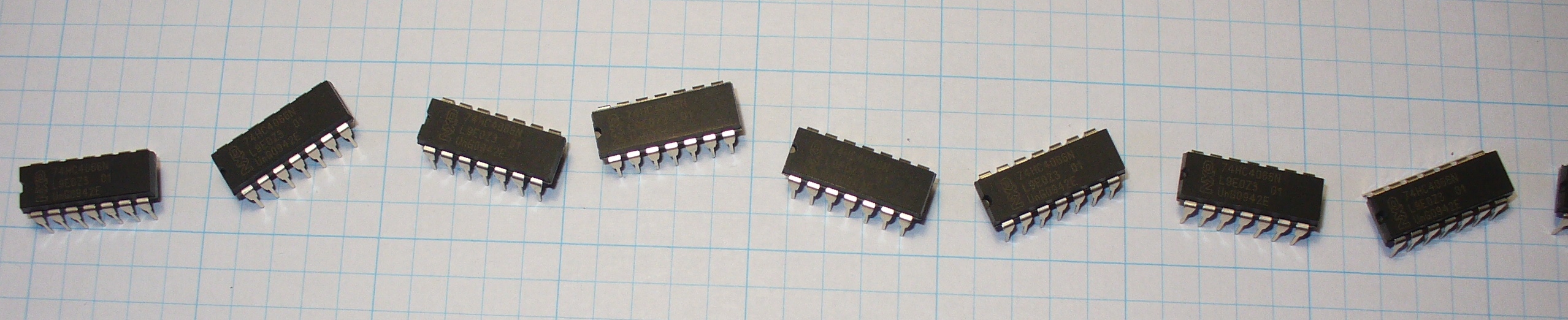
Photo Credit: oskay distributed under a Creative Commons license.

An Assorted Resistor Kit is a Great Starting Point

Joe Knows Electronics 1/4W 86 Value 860 Piece Resistor Kit

Assorted Resistor Kit by Jow Knows ElectronicsI recently bought this kit for myself, and I am happy with it. The resistors come nicely packed and well-organized.

There is a label on top of the box, as well as separate labels that you can stick to each individual bag.

This nifty kit contains 10 each of the 86 most common resistor values, ranging from 0 Ohm to 10M Ohm.

Law? What Law?

Ohm’s Law: a snapshotOhm's Law Triangle Diagram

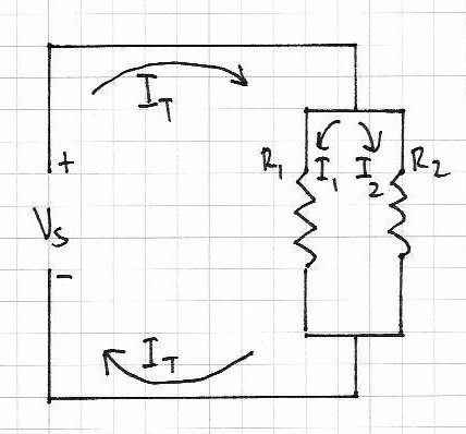
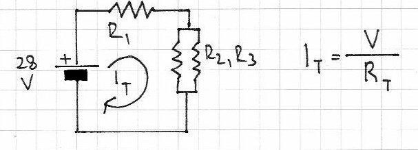
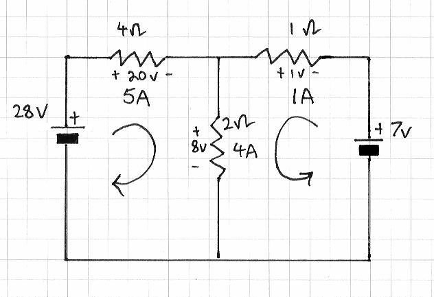
In the diagram to the right you can see a simple circuit illustrating the three variables whose relationship is defined by the Ohm’s Law: Voltage (V), Resistance (R) and Current (I).

The law states that “the current (i) between two points of a conductor is directly proportional to the potential difference (V) across these two points” and is described by the following mathematical expression:

V = IR, where V is the voltage (in volts) across the points marked “+” and “-” in the circuit, R is the resistance (in ohms) of the conductor (the zig-zagged portion in the circuit) and I is the current (in amperes) that flows through the conductor.

For a complete explanation of the Ohm’s Law, read this Wikipedia article.

* Image credit: the two images that were merged together here were kindly released into the public domain by its creators.

Array of LEDs

An Example of Ohm’s Law Applied to a Circuit

A simple Arduino experiment to flash LEDs

OK, so here’s a simple example:

One of the experiments you can perform with the Arduino is a device that can flash Light Emitting Diodes. An LED exhibits a very low resistance in the forward bias direction, so if you apply voltage in that direction from one of the Arduino IO pins without protection, a very large current will flow. This is likely to destroy the LED AND the Arduino in one nifty little “pop.”

Some LEDs have an internal current limiting resistor which prevent this, but it’s best to not take that chance unless you are absolutely sure (redundancy intended). You should put a resistor between the IO pin and the LED anode to keep the current under control.

The value of the resistor is determined by the current rating of the LED and a little math, using, you guessed it, Ohm’s Law!

Let’s say that the LED draws about 10 milliamps of current when fully lit. The Arduino IO pin will usually supply 5 volts in an active high state, so with Ohm’s Law, the voltage divided by the current will equal the amount of resistance required (we’ll ignore the internal voltage drop on the diode here for simplicity).

Doing the math (5 volts divided by .010 amps) yields a resistance value of about 500 ohms. Resistors aren’t available in exactly 500 ohm values, but we can find one at 510 ohms.

There! Now your Arduino is safe from harm!

* Image credit: generously shared under a Creative Commons license by cibomahto, on Flickr.

Want to Get Your Hands “Dirty”?

Here’s a great hands-on volume to keep you mildly challenged and highly entertained!

arduino workshop project book

John Boxall of tronixstuff fame does a great job writing tutorials on his blog, and he now has made it even easier for us to play with the Arduino by bundling 65 awesome projects in his book “Arduino Workshop: A Hands-On Introduction with 65 Projects“.

The 65 DIY projects in this book go from basic to intermediate to sophisticated, as your knowledge of and comfort with the Arduino grow. (I guarantee it will. The learning journey this volume takes you on is painless and fun!)

With fun projects such as digital thermometers and dice, secretly coded lock, GPS logger, binary quiz game and several more, the “Arduino Workshop” will take you from apprentice to sorcerer!

Hint: modifying projects to do things differently or to extend functionality highly encouraged!

But wait!

There’s more!

There is one more thing to say about the Arduino.

Although the single IO pins have individual values, when you view the IO pins as a port and use several simultaneously, there is also a maximum amount of current that can be drawn or dissipated by the combined group.

If you decide to manipulate the port registers,

you must calculate the TOTAL current for all pins in a B, C, or D port configuration by adding the individual values and making sure the sum doesn’t exceed the total allowed for the group.

There are several Arduino web sites that can provide exact values of current and pin configurations for all the different Arduino boards.

A good starting point is the official Arduino website, at arduino.cc. More specifically, this reference article on port manipulation.

And, of course, last, but not least, HAVE FUN tinkering with your new Arduino board!

Arduino Protection: How to Make Sure Your Project Won’t Kill Your Arduino originally appeared on Tinker Hobby on February 18, 2014.

OK, so you’ve bought one of the Arduino boards, downloaded some development software, and figured out how to talk to the Arduino to do simple tasks. Now you want to introduce Arduino to the outside world, so you’ll have to learn something about electronics in order to keep that “magic smoke” (more like the odoriferous […]
Jul
27

Arduino RGB LED Control for the Spinning Night Light | Part 4

arduino, light, Ohm's law, project, resistor, RGB LED, sketch, spinning night light Comments Off on Arduino RGB LED Control for the Spinning Night Light | Part 4 

When looking at the parts list for the Arduino RGB LED spinning night light you must have noticed that current limiting resistors of different values were used for the Red and the Green/Blue pins of the RGB LED. That is due to them having different forward voltage ratings. You can find complete specs for the LED in the datasheet (when buying an electronic component you will have the option to download its datasheet, or the relevant information will be provided by the vendor).

We use Ohm’s Law to calculate current limiting resistor values:

Forward voltage ratings:

RED: 2.1V
GREEN: 3.3V
BLUE: 3.3V

Current:

I = 20mA

Supply voltage:

V = 5V

Ohm’s Law:

I = V/R => R = V/I

So for Red:

(5 – 2.1)/0.02 => R = 145 Ohm

For Green/Blue:

(5 – 3.3)/0.02 => R = 85 Ohm

color fading for the RGB LED night lightAs for the Arduino sketch, I chose to have the lamp fade between two colors, aqua (#00FFFF) and magenta (#FF00FF). For that I kept the Blue value at 255 and varied the Green and Red values between 0-255 to achieve the desired colors, as shown in the diagram:
(You can pick your favorite colors, cycle through the entire spectrum, or go psychedelic and show random colors with random delays)

// fade from aqua to magenta
  for (int i = 0; i < 256; i++) {
    analogWrite(RED, 255-i);
    analogWrite(GREEN, i);
    analogWrite(BLUE, 0);
    delay(50);
  }

  // fade from magenta to aqua
  for (int i = 0; i < 256; i++) {
    analogWrite(RED, i);
    analogWrite(GREEN, 255-i);
    analogWrite(BLUE, 0);
    delay(50);
  }

Here’s the full sketch for the night light.

Arduino RGB LED Control for the Spinning Night Light | Part 4 originally appeared on Tinker Hobby on July 27, 2010.

Hello readers

Today we continue with the series of articles on basic electronics with this continuation of the article about the resistor. Part one can be found here.

With regards to this article, it is only concerned with direct current (DC) circuits.

In this chapter we will examine how two or more resistors alter the flow of current in various ways. First of all, let’s recap what we learned in the previous chapter.

Ohm’s Law – the relationship between voltage, current and resistance:

Resistors in series:


Resistors in parallel:

Dividing voltage with resistors:

However the fun doesn’t stop there. As there is a relationship between voltage, current and resistance, we can also divide current with resistors. For now we will see how this works with two resistors. Please consider the following:

There is a balance between the two resistors with regards to the amount of current each can handle. The sum of the current through both resistors is the total current flowing through the circuit (It). The greater the resistance the less current will flow, and vice versa. That is, they are inversely proportional. And if R1 = R2, I1 = I2. Therefore, I1/I2=R2/R1 – or you can re-arrange the formula to find the other variables.

Here is an example of doing just that:

Our problem here – there is 6 volts DC at half an amp running from left to right, and we want to use an indicator LED in line with the current. However the LED only needs 2 volts at 20mA. What value should the resistors be?

First of all, let’s look at R1. It needs to change 6V to 2V, and only allow 20 mA to pass. R=E/A or R= 4 volts /0.2 amps = 200 ohms.

So R1 is 200 ohms. I1 is .02 A. Now we know that the total current is equal to I1+I2, so I2 will be 0.48A. That leaves us with the known unknown R2 :)  We can re-arrange the formula R2/R1=I1/I2 to get R2 = (R1 x I1)/I2 – which gives us R2 of 8.3 ohms. Naturally this is a hypothetical, but I hope you now understand the relationship between the current through the resistors, and their actual resistance.

What we have just demonstrated in the problem above is an example of Kirchhoff’s current law (KCL). Gustav Kirchhoff was another amazing German physicist who worked on the understandings of electrical circuits amongst other things. More on GK here. His current law states that the amount of current entering a junction in a circuit must be equal to the sum of the currents leaving that junction. And not-coincidentally, there is also Kirchhoff’s voltage law (KVL) – the amount of voltage supplied to a circuit must equal the sum of the voltage drops in the circuit. These two laws also confirm one of the basic rules of physics – energy can not be created nor destroyed, only changed into different forms.

Here is a final way of wrapping up both KCL and KVL in one example:

The current through R3 is equal to I1 + I2

Therefore, using Ohm’s law, V1 = R1I1 + (R3 x (I1+I2)) and V2 = R2I2 + (R3 x (I1+I2))

So with some basic algebra you can determine various unknowns. If algebra is your unknown, here is a page of links to free mathematics books, or have a poke around BetterWorldBooks.

There is also another way of finding the currents and voltages in a circuit with two or more sources of supply – the Superposition Theorem.

This involves removing all the sources of power (except for one) at a time, then using the rules of series and parallel resistors to calculate the current and voltage drops across the other components in the circuit. Then once you have all the values calculated with respect to each power source, you superimpose them (by adding them together algebraically) to find the voltages and currents when all the power sources are active. It sounds complex, but when you follow this example below, you will find it is quite simple. And a lot easier the th.. fourth time.  Just be methodical and take care with your notes and calculations. So let’s go!

Consider this circuit:

With the Superposition theorem we can determine the current flowing through the resistors, the voltage drops across them, and the direction in which the current flows. With our example circuit, the first thing to do is replace the 7V power source with a link:

Next, we can determine the current values. We can use Ohm’s law for this. What we have is one power source, and R1 which is in series with R2/R3 (two parallel resistors). The total current in the circuit runs through R1, so calculate this first. It may help to think of the resistors in this way:

Then the formula for Rt is simple (above), and Rt is And now that we have a value for Rt, and the voltage (28V) the current is simple:

Which gives us a value of 6 amps for It. This current flows through R1, so the current for R1 is also 6 amps.

Next, the current through R2:

Using Kirchhoff’s Current Law, the current flowing through R2 and R2 will equal It. So, this is 4 amps.

At this point, note down what we know so far:

For source voltage 28V, Ir1 = 6A, Ir2 = 2A and Ir3 = 4A; R1=4 ohms, R2 = 2 ohms, R3 = 1 ohm.

Now – repeat the process by removing the 28V source and returning the 7V source, that is:

The total resistance Rt:

Gives us Rt = 2.3333 ohms (or 2 1/3);

Total current It will be 7 volts/Rt = 3 amps, so Ir3 = 3;

So Ir2 = 2A – therefore using KCL Ir1 = 3-2 = 1A.

So, with 7V source: Ir1 = 1A, Ir2 = 2A and Ir3 = 3A.

Next, we calculate the voltage drop across each resistor, again by using only one voltage source at a time. Using Ohm’s law, voltage = current x resistance.

For 28V:

Vr1 = 4 x 6 = 24V; Vr2 = 2 x 2 = 4V; Vr3 = 4 x 1 = 4V. Recall that R2 and R3 are in parallel, so the total voltage drop (24 + 4V) = 28 V which is the supply voltage.

Now, for 7V:

Vr1 = 4V, Vr2 = 4V, Vr3 = 3V.

Phew – almost there. Now time to superimpose all the data onto the schematic to map out the current flow and voltage drops when both power sources are in use:

Finally, we combine the voltage values together, and the current values together. If the arrow is on the left, it is positive; on the right – negative. So:

Current – Ir1 = 6 – 1 = 5A; Ir2 = 2 +2 = 4A; Ir3 = 4-3 = 1A;
Voltage – Vr1 = 24 – 4 = 20V; Vr2 = 4 + 4 = 8V; Vr3 = 4 – 3 = 1V.

And with a deep breath we can proudly show the results of the investigation:

So that is how you use the Superposition theorem. However, there are some things you must take note of:

  • the theorem only works for circuits that can be reduced to series and parallel combinations for each of the power sources
  • only works when the equations are linear (i.e. straight line results, no powers, complex numbers, etc)
  • will not work when resistance changes with temperature, current and so on
  • all components must behave the same way regardless to polarity
  • you cannot calculate power (watts) with this theorem, as it is non-linear.

Well that is enough for today. I hope you understood and can apply what we have discussed today. The final chapter on resistors can be found here.

As always, thank you for reading and I look forward to your comments and so on. Furthermore, don’t be shy in pointing out errors or places that could use improvement. Please subscribe using one of the methods at the top-right of this web page to receive updates on new posts. Or join our new Google Group.

Otherwise, have fun, be good to each other – and make something! :)

Notes: In writing this post, I used information from allaboutcircuits.com, plus information  from various books by Forrest Mims III and “Practical Electronics Handbook” 4th ed., Ian Sinclair. And used a lot of paper working out the theorem for myself. Thank you!


  • Newsletter

    Sign up for the PlanetArduino Newsletter, which delivers the most popular articles via e-mail to your inbox every week. Just fill in the information below and submit.

  • Like Us on Facebook