Posts | Comments

Planet Arduino

Archive for the ‘Arduino Project’ Category

Wanna start your bike without a key? Yes, we have made a project for all tech enthusiasts who wanna integrate the technology into their bikes. with the help of keyless bike project, you can control your bike fully like starting the engine and ignition of the bike. and you can locate your bike by clicking on the locate bike key. i think this is a very interesting project. Also, I will attach this product in my bike too soon and the video will be uploaded on my youtube and Instagram.

Introductions

This keyless bike Arduino project is very easy to use. There is one application for Android mobile phone. through this application you can control your bike properly.

  1. you can turn on and off your bike
  2. you can on self start the bike
  3. you can locate your bike by horn and indicator control

these things you can control by our project. we will use wireless communication to connect the bike with the mobile phone.

To make this project we are going to share all the detail here. if you really want to learn and make this project follow all the steps. you need to learn some basics of electronics which are already given on our website. So, let get started with any delay.

First we need to make a list of required components.

Required components

  • Arduino nano
  • Bluetooth HC-05
  • LEDs
  • 4 channel relay
  • Usb A type cable
  • Breadboard
  • Hook up wires

As you can read in the required components you need only a few components to make this keyless bike project. Now, let’s try to understand what is the purposes of the given components.

Arduino nano is controller and uses as a main part of this task. Arduino nano have the capability to store the data, compare the data, operate sensors , modules and much more. so , arduino nano is controlling the Bluetooth module here. and relays. it getting the data on the Bluetooth module and compare this data with the programmed data and turn on and off relays.

Relays are the electronic switches. which can turn on and off any circuit by a small amount of current such as we need to press any key to turn of the light or fan same as the relay can turn off and on by applying a small voltage. so here we turn off and on the bikes things like ignition, engine, and indicator.

Bluetooth module is the wireless communication in this keyless bike project. which make the connection between bike and the mobile phone. we already make an android app which will connect the bike through the Bluetooth hc-o5 module. the app link is given below.

Download Android app.

Circuit diagram

Keyless bike Project circuit diagram

Code

void setup()  
 {  
 Serial.begin(9600); // buart rate  
 pinMode(12,OUTPUT); //
 pinMode(9,OUTPUT);
pinMode(10,OUTPUT);
 pinMode(11,OUTPUT); // LED  
 //digitalWrite(12,HIGH); // relay module high  
 }  
 void loop()  
 {  
 if(Serial.available()>0)  
 {  
 char data= Serial.read();  
 Serial.println(data);  
 if(data=='A')  
 {  
digitalWrite(10,HIGH);
 delay(300);
 digitalWrite(10,LOW);
 delay(300);
 digitalWrite(10,HIGH);
 delay(300);
 digitalWrite(10,LOW);
 delay(300);
 digitalWrite(10,HIGH);
 delay(300);
 digitalWrite(10,LOW);
 delay(300);
 digitalWrite(10,HIGH);
 delay(300);
 digitalWrite(10,LOW);
 delay(300);
 }  
 else if(data=='C')  
 {  
 
 digitalWrite(11,LOW); // LED OFF  
delay(500); 

 }  


 else if(data=='D')  
 {  
 
 digitalWrite(11, HIGH); // LED OFF  
delay(500); 

 }  


else if(data=='B')  
 {  
 
 digitalWrite(12,LOW); // LED OFF  
 delay(1000);
digitalWrite(12,HIGH); // LED OFF  
 delay(1000);

 }  

 else 
 {    }
 
 }  
 }

Upload the given code in your Arduino by connecting the cable. if you have any trouble uploading the sketch you can get help from our website.

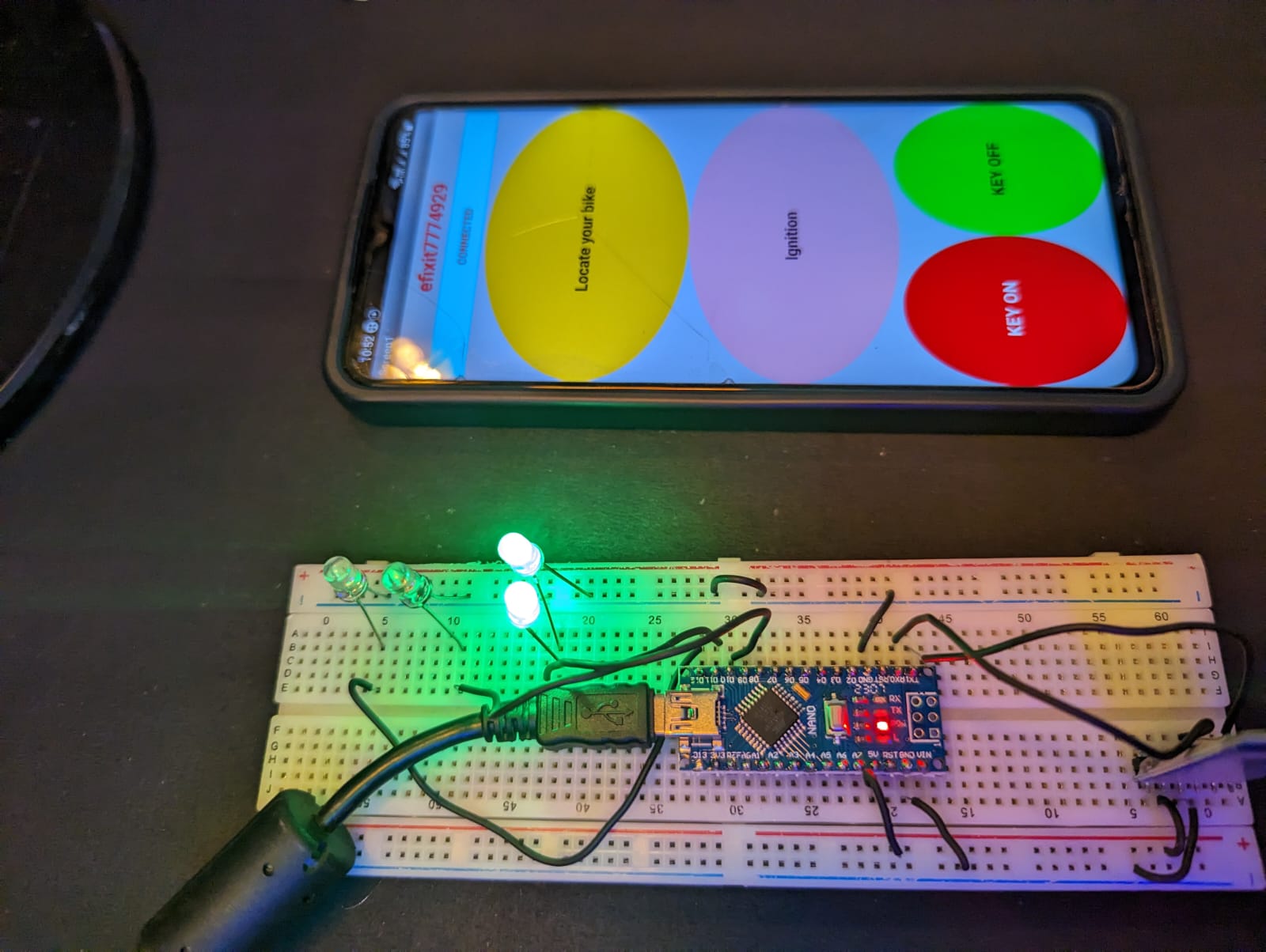
How to operate the application.

step.1

  • give power to the system
  • Go to the phone setting
  • select the Bluetooth setting
  • click on the pair new device tab
  • Select the HC-05 device there
  • now open the given application
  • click on the connect tab in application
  • select the HC-05 device

PCBWay PCB Prototyping Services

I have assembled the whole circuit on a breadboard. As you know breadboard assembly is not effective for this type of project. So, PCBWay offers Rapid PCB Prototyping for Your Research Work. I personally, recommend PCBWay because you can get your first-try boards right in 24 hours!

PCBWay website

The prototyping stage is the most critical period of time for engineers, students, and hobbyists. PCBWay not only makes your boards quick but also makes your job right as well as cost-effective. This greatly reduces your cost and shortens the time for developing your electronic

PCBWay can provide 2 Layer PCBs to highly advanced HDI and flex boards. Even though the PCBs they produce differ a lot regarding functionality and areas of use. I am impressed with the quality of the boards, the delivery time, and the cost-effectiveness

Keyless bike project Working

When application is connected to the device the connect tab will convert top the connected in the application. and when any key is press the phone will sends a character to the Bluetooth module which is attached to thee arduino and system.

For example if you press turn on bike tab in application the phone will sends ‘A’ to the Arduino and system and now Arduino will compare this data to the programmed we have written. if anything found to the similar to this data it will be start that condition.

like if (receive_data==’A’)

then, bike start.

if the condition is not true then bike will not start.

same in this way the whole system will work.

Thanks for reading, if you have any doubt you can ask us in comment section.

The post Keyless bike Project using Arduino and Android app appeared first on Techatronic.

Hey guys, welcome back to Techatronic. Today we will make an smart water heater project using Arduino and DS1820B temperature sensors. if you want to make a portable smart water heater for winter you can make this. this can be used in many things where we need a small , smart and safe water heater they can make this smart water heater.

Introduction

this is a very simple and useful project which can be used at many places. like if you are going anywhere you can carry it with you. these smart water heater are available in the market but this is unique and have some extra feature. so, if you want to make it simply you need to follow the given instructions.

if you have some prior experience in arduino , basic electronics then it will be very easy for you to make this. also, you can learn basic electronics and Arduino programming from our recent article on our website.

We have made this full tutorial with code, circuit and step by step instruction. follow the given instructions and make this smart water heater project by yourself.

Components Required.

  • Arduino nano
  • 16×2 display
  • DS1820B temperature sensor
  • buzzer
  • push button
  • singal channel relay
  • potentiometer
  • Mini water heater

if you can arrange these given components you can make this awesome smart water heater.

Here the arduino nano is the main controller of this project. as we all know the Arduino is a microcontroller and can be control many things. like it can get the information from the sensors and also it is capable to operate the output devices. here the arduino nano getting all the information from the sensors like ultrasonic sensor and temperature sensor. according to the data collect from the sensor it operate the water heater by triggering the relay.

16×2 display is used to show or display the information of the system. in this smart water heater we are showing the current temperature, required temperature, level of water in the container, and operation instructions.

DS1820b is a waterproof temperature sensor. this is also known as the probe temperature sensor and can be use to detect the temperature for liquid.

In this smart water heater we are using 3 push button for set the temperature for water heater. 1st button increases the value and 2nd button decrease the value and third button set the values.

Circuit Diagram

Code


const int buttonPin1 = 2, buttonPin2 = 3;    
int button1_State = 0, button2_State = 0;
int count_value =0;
int prestate =0;
#include <LiquidCrystal.h>

// initialize the library by associating any needed LCD interface pin
// with the arduino pin number it is connected to
const int rs = 12, en = 11, d4 = 10, d5 = 9, d6 = 8, d7 = 7;
LiquidCrystal lcd(rs, en, d4, d5, d6, d7);

#include <OneWire.h>
#include <DallasTemperature.h>

// Data wire is conntec to the Arduino digital pin 4
#define ONE_WIRE_BUS 5

// Setup a oneWire instance to communicate with any OneWire devices
OneWire oneWire(ONE_WIRE_BUS);

// Pass our oneWire reference to Dallas Temperature sensor 
DallasTemperature sensors(&oneWire);

int duration=0;
long distance=0;
int firstduration=0;
long firstdistance=0;
int secondduration=0;
long seconddistance=0;

void setup() {
  // initialize the pushbutton pin as an input:
  sensors.begin();
  pinMode(buttonPin1, INPUT_PULLUP);
  pinMode(buttonPin2, INPUT_PULLUP);
  pinMode(4, INPUT_PULLUP);
  pinMode(A0, OUTPUT);
   pinMode(A1, OUTPUT);
  lcd.begin(16, 2);
  Serial.begin(9600);
  lcd.clear();
  lcd.setCursor(2, 0);
  lcd.print("SMART WATER");
  lcd.setCursor(5, 1);
  lcd.print("HEATER");
  digitalWrite(A0, LOW);
  digitalWrite(A1, HIGH);
 pinMode(A4,OUTPUT);
pinMode(A5,INPUT);
}

void loop() {

  
  // read the state of the pushbutton value:
  button1_State = digitalRead(buttonPin1);
  button2_State = digitalRead(buttonPin2);
  int m = digitalRead(4);
  // check if the pushbutton is pressed. If it is, the buttonState is HIGH:
  if (button1_State == LOW && prestate == 0) {
    count_value++;  
  
  Serial.println(count_value);
  lcd.clear();
  lcd.setCursor(0, 0);
  lcd.print("SET TEMPERATURE");
  lcd.setCursor(7, 1);
  lcd.print(count_value);
    prestate = 1;
    delay(100);
  }
//decrement
  else if (button2_State == LOW && prestate == 0) {
    count_value--;
  
  Serial.println(count_value);
  lcd.clear();
  lcd.setCursor(0, 0);
  lcd.print("SET TEMPERATURE");
  lcd.setCursor(7, 1);
  lcd.print(count_value);
   prestate = 1;
    delay(100);
  } 

else if(m==0)


{
digitalWrite(A4, HIGH);
   delayMicroseconds(10);
   digitalWrite(A4, LOW);
   delayMicroseconds(2);
   duration= pulseIn(A5,HIGH);
   delay(100);
   distance=duration*0.034/2;
   Serial.println(distance);
   if(distance==3 || distance==4)
   {

  digitalWrite(A1, LOW);
   digitalWrite(A0, LOW);

    while(1)
  {
   
   lcd.clear();
  
  lcd.setCursor(11, 1);
  lcd.print(count_value);
  sensors.requestTemperatures(); 
  
  lcd.setCursor(2, 0);
  lcd.print("HEATER START");
  lcd.setCursor(2, 1);
  lcd.print(sensors.getTempCByIndex(0));
  delay(500);

  if(sensors.getTempCByIndex(0)>=count_value)

  {
   
     digitalWrite(A0, HIGH);
      digitalWrite(A1, HIGH);
     //delay(200);
    }
else
{
  digitalWrite(A0, LOW);
      digitalWrite(A1, LOW);
  
  }


  }
   }

   else 

   {

    lcd.clear();
  lcd.setCursor(0, 0);
  lcd.print("FILL MORE WATER");
  lcd.setCursor(0, 1);
  lcd.print(distance);
    digitalWrite(A1, HIGH);
   //digitalWrite(A0, LOW);
    
    }
 
}
  
 else if(button1_State == HIGH && button2_State == HIGH) {
    prestate = 0;
  }
  
}

Upload code to your Arduino Nano with the help of a USB micro cable.

Smart Water heater Working

smart water heater arduino project

the display show you all the instructions how the system will work. first, you have to fill the container. make sure the water level should be good enough to operate the water heater. after that, press the 1st push button and increase the temperature as you need. you can decrease the temperature with another button. and now press third button to set the temperature. the system will start the water heater till the required temperature achieve.

PCBWay PCB Prototyping Services

I have assembled the whole circuit on a breadboard. As you know breadboard assembly is not effective for this type of project. So, PCBWay offers Rapid PCB Prototyping for Your Research Work. I personally, recommend PCBWay because you can get your first-try boards right in 24 hours!

PCBWay website

The prototyping stage is the most critical period of time for engineers, students, and hobbyists. PCBWay not only makes your boards quick but also makes your job right as well as cost-effective. This greatly reduces your cost and shortens the time for developing your electronic

PCBWay can provide 2 Layer PCBs to highly advanced HDI and flex boards. Even though the PCBs they produce differ a lot regarding functionality and areas of use. I am impressed with the quality of the boards, the delivery time, and the cost-effectiveness

once it found the required temperature in water then it will stop the water heater with a buzzer sound.

The post Smart water heater using Arduino DIY Project appeared first on Techatronic.

Hello readers

In this article you can follow the process of making another LCD shield for the Arduino Duemilanove or compatible boards. In the past (which explains the word another in this title) I made a 16 x 2 character LCD shield, however it was not backlit, nor large enough. Recently I acquired a 20 x 4 character backlit LCD for use in my Arduino tutorials, therein making this project necessary. To refresh your memories, here is the original shield:

However this time, I cannot mount the display on the shield, it is just too large. Furthermore, it is preferable to be able to stack other shields on top of the new LCD shield. Therefore the display will be external and connected with lengths of wire. So time to get cracking. The first step was to assemble all the parts together. The new LCD has a standard 16-pin  HD44780 interface, and is very easy to connect:

What we have: one 20×4 character backlit LCD, a Freetronics basic protoshield, some stacking pin headers, a button, 10k ohm trimpot for contrast adjustment, and some spacers and matching screws to give the LCD some legs. Afterwards I got some 0.1uF ceramic capacitors as well, to smooth supply current on the 5V rail of the shield. Here is the data sheet for the LCD: 2004 LCD.pdf.

As usual the first thing to do was to make a plan. The LCD interface is easy enough, but I still like to have something on paper to refer to:

The next step is to breadboard it – to make sure it works. However I did solder in the wires to the LCD at this stage:

And after assembling the circuit, a brief test:

Success. The demonstration sketch is the example provided with the Arduino IDE, modified for a 20×04 LCD – 2004LCDdemo.pdf. During the test above, I used an external 5V power supply for the breadboard. Remember to connect the ground line from the Arduino to the ground line of your breadboard, otherwise it will not work. At this point I was wondering how much current the LCD used by itself. The data sheet claimed it was five milliamps… I think not. Mr Multimeter had a different opinion:

Now it was time to finish the soldering work. Instead of trying to jam all the wires together along the digital pins, I used some wire jumpers to spread out the landing points for the wires from the LCD.

Furthermore, I decided to install a power LED and 560 ohm resistor – you can never have too many LEDs. :) The rear of the protoshield was also quite neat, dollops of solder easily bridged pads when required. Then after a visual inspection it was time to solder in the header pins. The easiest way to do this is to use an existing shield:

After soldering in the pins, the first attempt of using the display was unsuccessful. I had confused a couple of wires, but some reprogramming of the sketch fixed that. (It was Saturday night and my eyes were tired). But once the error had been fixed – success!

If this shield/display needed a name, I would call it the Dog’s breakfast. Now, hardware is only half of the solution – there are one or two things to take into account when writing your sketch. If you do not have the latest version of the Arduino IDE (v18), upgrade so you will have the new LiquidCrystal library. Also, when using .setCursor(x,y); to position the cursor, the top left position on the LCD is 0,0; and the bottom right is 19,3. For example, the image below was created by:

lcd.setCursor(0, 0);
lcd.print("A");
lcd.setCursor(1,1);
lcd.print("B");
lcd.setCursor(2,2);
lcd.print("C");
lcd.setCursor(3,3);
lcd.print("D");

Now to make something slightly more useful to take advantage of the screen area – another clock! (I like clocks) using my DS1307 real time clock shield. Here is the sketch: worldclock.pdf, (doesn’t allow for DST) and an action shot:

Question – from which organisation did my LCD module come from? :)

So there you have it. Another way to use an LCD with an Arduino, and show how you can do things yourself.

If you have any questions at all please leave a comment (below). We also have a Google Group dedicated to the projects and related items on the website – please sign up, it’s free and we can all learn something. High resolution photos are available from flickr. This article is a guide – always check your own work before committing to construction.

Otherwise, have fun, stay safe, be good to each other – and make something! :)


Nov
18
ShapeWays.com

ShapeWays.com

ShapeWays.com has added a $50.00 Coupon to the ArduinoFun – Build It- contest! Have you ever wanted to turn your 3D designs into reality? Enter Shapeways! Just upload your design, we print it and ship it to you – it’s easy. Within ten working days you’ll hold your own design in your hands.

But that’s not all – we’re offering you everything you need to meet fellow Shapeways users, share your work and find inspiration.

We’re using a technique called ‘3D Printing’ which has proven itself as a high-quality production technique, but up to now has always been very expensive. By creating a large community we are able to produce much cheaper, meaning better prices for you.

Enter your Arduino project today!

Prizes:

Share/Bookmark
Side view

Side view

Contest Entry by Steve Hoefer

How many times have you seen a secret hideout with a secret knock?  It’s a staple of cheesy dramas, Saturday afternoon movies, and tree houses throughout the world.

While working on another project I ran across the Arduino knock sensor tutorial.  Sensing a single knock is a great little project for learning about microcontrollers, but what about sensing specific knocks?  Seeeeecret knocks?  And if we could detect a secret knock, shouldn’t it unlock a door?   If you can’t tell by looking this was cobbled together from spare stuff around the lab, it’s not much more than a piezo speaker, a tiny gear reduction motor, and an Arduino. And PVC pipe.

**Disclaimer: This was built with stuff I had lying around the lab.  How about a video to explain:

A microphone (okay, really a speaker) presses against the door and listens for knocks.  If it hears the right number of knocks in the right cadence it triggers the motor to turn the deadbolt and unlock the door.  If the sequence isn’t recognized, the system resets and listens for knocks again.

The default code is Shave and a Hair Cut but if that’s too obvious you can enter a new knock sequence by holding down the red button and knocking your new secret knock (up to 20 knocks).  The rhythm of your favorite song, Morse code, whatever!  The widget will play back your knock (by blinking the lights) so you can be sure it heard everything correctly.

The whole thing is attached to the door with suction cups

The components are simple, most of the work is done in the microcontroller.  The source code for the Arduino is available at the bottom of the page if you’re curious.

How does it work?

First it records the time between knocks.  If there is a long wait for a knock it stops listening and starts analyzing.

Basic circuity

Basic circuity

First it checks the number of knocks.  If that’s right, we go on to more vigorous authentication.   First it converts the absolute timing of the knocks to the rhythm of the knocks.  This lets us knock fast or slow and as long as we get the rhythm right it will unlock.  That way I can still unlock the door if I’m tired or full of caffeine.  After this it compares the timing with the secret key and if any individual knock is off by too much or the whole thing is off by a certain average amount the door stays locked.  If not, we trigger the motor to turn and the lock to unlock.  If the programming button is pressed it saves the rhythm information and then plays it back.

The detection is surprisingly accurate and can even be dialed up so it’s precise enough  to detect an individual person’s variation on a knock, similar to a Morse coder’s ‘fist‘.  (Though when the verifying is this tight it also triggers false negatives which are annoying.)

To keep things simple (and it’s because it’s what I had available) a motor is attached to the deadbolt using two pieces of spring steel bolted across the D shaft of the motor so that the connection will slip when the lock turns as far as it can. A more precise (and probably durable) way to do it would be to use a servo to turn the lock or have a detector sense when the lock had reached its extent.  Or replace the dead bolt with a solenoid.  Or whatever else you can think of.

Circuit fitting

Circuit fitting

The rest of the electronics are nothing special.  Its so simple that just adding feedback LEDs almost doubled the parts count.  The Arduino has a lot of unused potential on this project.

No proper schematic yet, but there’s a layout and parts list at the bottom of the page. Look for a fully documented Instructable soon.

With some extra electronics (an H-bridge) it would be possible to have the door automatically lock as well as unlock. Other improvements or changes that someone could do:

  • Adding a knob to adjust the sensitivity.
  • Building it into an actual door knocker.
  • Using a more economical microcontroller and enabling a sleep mode for better battery life.
  • Making the whole package small enough to fit inside the door.
  • Storing several knocks so several people can have their own private knocks.
  • Adding a real-time clock and using different knocks for different days of the week or times of day.
  • Listening for door bell presses rather than door knocks.
  • Adding a servo or solenoid powered knocker to provide feedback through the door.  It could then offer a challenge-response security where the door starts a knock sequence and the user has to finish it correctly.
  • Rather than listening for knocks, putting a photoresistor in the peep hole and detecting flashes of light from a pocket flashlight or simply by placing your hand over the peephole. Or an infrared receiver and use special key presses on a remote control.
Knock sensor layout (click for larger view)

Knock sensor layout (click for larger view)

Do I have to point out that this is not a great security measure since overhearing a knock sequence is pretty trivial?  No.  But it’s fun to make and play with.

Here’s my code: If you have trouble with cut and paste below you can download the .pde file here.

  1. /* Detects patterns of knocks and triggers a motor to unlock
  2. it if the pattern is correct.
  3.  
  4. By Steve Hoefer http://grathio.com
  5. Version 0.1.09.10.24
  6. Licensed under Creative Commons Attribution-Noncommercial-Share Alike 3.0
  7.  
  8. Analog Pin 0: Piezo speaker (connected to ground with 1M pulldown resistor)
  9. Digital Pin 2: Switch to enter a new code.  Short this to enter programming mode.
  10. Digital Pin 3: DC gear reduction motor attached to the lock. (Or a motor controller or
  11. a solenoid or other unlocking mechanisim.)
  12. Digital Pin 4: Green LED.
  13. Digital Pin 5: Red LED.
  14. */
  15.  
  16. // Pin definitions
  17. const int knockSensor = 0;
  18. // Piezo sensor on pin 0.
  19. const int programSwitch = 2;
  20. // If this is high we program a new code.
  21. const int lockMotor = 3;
  22. // Gear motor used to turn the lock.
  23. const int redLED = 4;
  24. // Status LED
  25. const int greenLED = 5;
  26. // Status LED
  27.  
  28. // Tuning constants.
  29. // Could be made vars and hooked to potentiometers for soft configuration, etc.
  30. const int threshold = 4;
  31. // Minimum signal from the piezo to register as a knock
  32. const int rejectValue = 25;
  33. // If an individual knock is off by this percentage of a knock we don’t unlock..
  34. const int averageRejectValue = 15;
  35. // If the average timing of the knocks is off by this percent we don’t unlock.
  36. const int knockFadeTime = 150;
  37. // milliseconds we allow a knock to fade before we listen for another one. (Debounce timer.)
  38. const int lockTurnTime = 450;
  39. // milliseconds that we run the motor to get it to go a half turn.
  40.  
  41. const int maximumKnocks = 20;
  42. // Maximum number of knocks to listen for.
  43. const int knockComplete = 1200;
  44. // Longest time to wait for a knock before we assume that it’s finished.
  45.  
  46. // Variables.
  47. int secretCode[maximumKnocks] = {50, 25, 25, 50, 100, 50, 0, 0, 0, 0, 0, 0, 0, 0, 0, 0, 0, 0, 0, 0};
  48. // Initial setup: "Shave and a Hair Cut, two bits."
  49. int knockReadings[maximumKnocks];
  50. // When someone knocks this array fills with delays between knocks.
  51. int knockSensorValue = 0; // Last reading of the knock sensor.
  52.  
  53. void setup() {
  54. pinMode(knockSensor, OUTPUT);
  55. pinMode(lockMotor, OUTPUT);
  56. pinMode(redLED, OUTPUT);
  57. pinMode(greenLED, OUTPUT);
  58. pinMode(programSwitch, INPUT);
  59.  
  60. //Serial.begin(19200);
  61. // Uncomment the Serial.bla lines for debugging.
  62. //Serial.println("Program start.");  // This line too.
  63.  
  64. digitalWrite(greenLED, HIGH);
  65. // Green LED on, everything is go.
  66. }
  67.  
  68. void loop() {
  69. // Listen for any knock at all.
  70. knockSensorValue = analogRead(knockSensor);
  71. if (knockSensorValue >=threshold){
  72. listenToSecretKnock();
  73.   }
  74. }
  75.  
  76. // Records the timing of knocks.
  77. void listenToSecretKnock(){
  78. //Serial.println("knock starting");    // debug.
  79. int i = 0;
  80. // First lets reset the listening array.
  81. for (i=0;i=threshold){   //got another knock…
  82. //record the delay time.
  83. now=millis();
  84. knockReadings[currentKnockNumber] = now-startTime;
  85. currentKnockNumber ++;   //increment the counter
  86. startTime=now;
  87. // and reset our timer for the next knock
  88. digitalWrite(greenLED, LOW);
  89. delay(knockFadeTime);
  90. // again, a little delay to let the knock decay.
  91. digitalWrite(greenLED, HIGH);
  92. }
  93.  
  94. now=millis();
  95.  
  96. //did we timeout or run out of knocks?
  97. } while ((now-startTime < knockComplete) &amp;&amp; (currentKnockNumber < maximumKnocks));
  98.  
  99. //we’ve got our knock recorded, lets see if it’s valid
  100.  
  101. if (validateKnock() == true){
  102. triggerDoorUnlock();
  103. } else {
  104. //Serial.println("Secret knock failed.");
  105. digitalWrite(greenLED, LOW);
  106. // We didn’t unlock, so blink the red LED as visual feedback.
  107.     for (i=0;i<4;i++){
  108.       digitalWrite(redLED, HIGH);
  109.       delay(100);
  110.       digitalWrite(redLED, LOW);
  111.       delay(100);
  112.     }
  113.     digitalWrite(greenLED, HIGH);
  114.   }
  115. }
  116.  
  117. // Runs the motor (or whatever) to unlock the door.
  118. void triggerDoorUnlock(){
  119. //Serial.println("Door unlocked!");
  120. int i=0;
  121.  
  122. // turn the motor on for a bit.
  123. digitalWrite(lockMotor, HIGH);
  124. digitalWrite(greenLED, HIGH);
  125. // And the green LED too.
  126.  
  127. delay (lockTurnTime);   // Wait a bit.
  128.  
  129. digitalWrite(lockMotor, LOW);  // Turn the motor off.
  130.  
  131. // Blink the green LED a few times for more visual feedback.
  132. for (i=0; i < 5; i++){
  133. digitalWrite(greenLED, LOW);
  134. delay(100);
  135. digitalWrite(greenLED, HIGH);
  136. delay(100);
  137.   }
  138.  
  139. }
  140.  
  141. // Sees if our knock matches the secret.
  142. // returns true if it’s a good knock, false if it’s not.
  143. // todo: break it into smaller functions for readability.
  144. boolean validateKnock(){
  145. int i=0;
  146.  
  147. // simplest check first: Did we get the right number of knocks?
  148. int currentKnockCount = 0;
  149. int secretKnockCount = 0;
  150. int maxKnockInterval = 0;
  151. // We use this later to normalize the times.
  152.  
  153. for (i=0;i 0){
  154. currentKnockCount++;
  155.     }
  156. if (secretCode[i] > 0){  //todo: precalculate this.
  157. secretKnockCount++;
  158.     }
  159.  
  160. if (knockReadings[i] > maxKnockInterval){
  161. // collect normalization data while we’re looping.
  162. maxKnockInterval = knockReadings[i];
  163.     }
  164.   }
  165.  
  166. // If we’re recording a new knock, save the info and get out of here.
  167. if (digitalRead(programSwitch)==HIGH){
  168. for (i=0;i< maximumKnocks ; i++){
  169. digitalWrite(greenLED, LOW);
  170. digitalWrite(redLED, LOW); // only turn it on if there’s a delay
  171. if (secretCode[i] > 0){
  172. delay( map(secretCode[i],0, 100, 0, maxKnockInterval));
  173. // Expand the time back out to what it was.  Roughly.
  174. digitalWrite(greenLED, HIGH);
  175. digitalWrite(redLED, HIGH);
  176.         }
  177. delay(50);
  178.       }
  179. return false;
  180. // We don’t unlock the door when we are recording a new knock.
  181.   }
  182.  
  183. if (currentKnockCount != secretKnockCount){
  184. return false;
  185.   }
  186.  
  187. /*  Now we compare the relative intervals of our knocks, not the absolute time between them.
  188. (ie: if you do the same pattern slow or fast it should still open the door.)
  189. This makes it less picky, which while making it less secure can also make it
  190. less of a pain to use if you’re tempo is a little slow or fast.
  191. */
  192. int totaltimeDifferences=0;
  193. int timeDiff=0;
  194. for (i=0;i rejectValue){ // Individual value too far out of whack
  195. return false;
  196.     }
  197. totaltimeDifferences += timeDiff;
  198.   }
  199. // It can also fail if the whole thing is too inaccurate.
  200. if (totaltimeDifferences/secretKnockCount>averageRejectValue){
  201. return false;
  202.   }
  203.  
  204. return true;
  205.  
  206. }
Share/Bookmark
Silly String Spider

Silly String Spider

Contest Entry by Todd Harrison

I had great fun this Halloween with a silly string shooting spider!  My plan was to use an Arduino micro-controller developer board to control my son’s “Teenage Mutant Ninja Turtle” RC car that already shoots silly string.  I didn’t get the spider to actually squirt the silly string but when you’re looking at a big black spider and something shoots silly string at you from the same direction it scares you just the same.

I was inspired to do this 4 hour marathon build by a blog posting by Eric on www.Instructables.com. Eric created a silly string shooting pumpkin which was so incredible I just had to build a spider for Halloween that did the same.

My major problem was that once I heard about Eric’s pumpkin I only had a day to get the supplies and about 4 hours of free time to wire-up something, code it and get it out in the front yard before the kids started coming for tricks or treats.

Here is a component breakdown of the final prop.

  • The red dot and arrow point to the RC car hiding under a bush.
  • 2) RC car remote control.
  • 3) Relay used by pin 2 on the Arduino to fire the remote control’s silly string button.
  • 4) Arduino board: Duemilanove with ATmega328 Purchased from adafruit.com
  • 5) Small blue servo to yank on the spiders leg: TowerPro SG-50.
  • 6) Two red LEDs for spider eyes. Not on the spider I know, I ran out of dev time
  • 7) Parallax Ping))) sonar sensor, held up with helping hands.
  • 8 ) Big black spider
Silly String Spider Parts

Silly String Spider Parts

I originally wanted the string to shoot from the spider’s behind but I really didn’t have time for that so I hid the RC car in the bushes behind the spider and loaded it with a fresh can of silly string.  All I really had to do was get the Arduino to sense somebody getting to close to the spider’s face and then “POW!” fire the silly string using the car’s remote control.

Just for extra effect I wanted the spider to move using a servo and have red LED eyes that blinked.  I also wanted the blinking and servo movement to ramp up faster and faster as a person got closer. To get this effect I used a Parallax Ping))) sonar sensor to track the approaching prey as well as to calculate an agitation delay.  The agitation delay was used to make the spider look more and more upset as the person got closer. If somebody was at a great distance the LED eyes flashed slow and the spider made slow jerking motions, but as the distance delay multiplier shortened the eyes flash furiously fast and the spider would jerk like mad!  If the trick-or-treater dared get closer the Arduino would fire a relay connected to the remote control and they would get a face full of silly string.

Silly String Spider Board Control

Silly String Spider Board Control

A lot of people did have the nerve to walk up on the spider but in the dark it took them a second to even realize they had just been doused in the face with silly string, but then they would laugh and do it again just for fun.  It only really scared a few that didn’t expect anything or were just standing behind the intended victim who was fortunately to short to get hit.

I didn’t get time to mount the eyes in the spider’s head but the red flashing LEDs on the control board seemed to have the same effect as they would have had if they were on the spider.  They were only needed to get the kids attention in the dark.

Arduino Sketch:

  1. #include
  2. Servo myservo;  // create servo object to control a servo
  3.  
  4. int pingPin = 7; // pin for ping sensor
  5. int stringPin = 2; // pin that will fire the silly string remote
  6. int LED_Eyes_Pin = 11; // pin for the two eyes
  7. int multiplier; // multiplier for delay
  8. int delay_time; // time to delay before next step
  9.  
  10. void setup() {
  11.   pinMode(LED_Eyes_Pin, OUTPUT);
  12.   pinMode(stringPin, OUTPUT);
  13.   myservo.attach(9);  // attaches the servo on pin 9 to the servo object
  14.   Serial.begin(9600);
  15.   digitalWrite(stringPin, LOW);    //make sure this is off so we don’t shoot string
  16. }
  17.  
  18. void loop() {
  19.   ping();
  20.   eyes_and_servo(0,0);
  21.   delay(delay_time);
  22.  
  23.   ping();
  24.   eyes_and_servo(100,255);
  25.   delay(delay_time);
  26. }
  27.  
  28. void eyes_and_servo(int servo_pos, int eye_pulse)
  29. {
  30.   analogWrite(LED_Eyes_Pin, eye_pulse);
  31.   myservo.write(servo_pos);
  32. }
  33.  
  34. void ping()
  35. {  long duration, inches;
  36.  
  37.   // The PING))) is triggered by a HIGH pulse of 2 or more microseconds.
  38.   // We give a short LOW pulse beforehand to ensure a clean HIGH pulse.
  39.   pinMode(pingPin, OUTPUT);
  40.   digitalWrite(pingPin, LOW);
  41.   delayMicroseconds(2);
  42.   digitalWrite(pingPin, HIGH);
  43.   delayMicroseconds(5);
  44.   digitalWrite(pingPin, LOW);
  45.  
  46.   // The same pin is used to read the signal from the PING))): a HIGH
  47.   // pulse whose duration is the time (in microseconds) from the sending
  48.   // of the ping to the reception of its echo off of an object.
  49.   pinMode(pingPin, INPUT);
  50.   duration = pulseIn(pingPin, HIGH);
  51.   // convert the time into a distance
  52.   inches = microsecondsToInches(duration);
  53.   multiplier = inches/10;
  54.  
  55.   delay_time = inches * multiplier;
  56.  
  57.   if (delay_time > 1000) {delay_time = 500;};
  58.  
  59.   if (delay_time < 300) {
  60.      digitalWrite(stringPin, HIGH);
  61.      delay(500);
  62.      digitalWrite(stringPin, LOW);
  63.      delay(2000);
  64.    };
  65.  
  66.   Serial.print(delay_time);
  67.   Serial.print(” delay time; inches are= “);
  68.   Serial.print(inches);
  69.   Serial.println();
  70. }
  71.  
  72. long microsecondsToInches(long microseconds)
  73. {
  74.   return microseconds / 74 / 2;
  75. }

Project Videos

Share/Bookmark

Halloween Dropping Spider

Halloween Dropping Spider

Contest Entry by Noel Portugal

My Halloween project consisted of a dropping spider triggered by a PIR motion sensor mounted on a Jackolantern. The motion sensor triggered a dropping spider, lights, sounds, low laying fog and finally a tweet with a picture attached.

Setup: It’s all pretty basic. The arduino controlled the PIR motion sensor, the servos for dropping spider reel, Jackolantern LED lights, toy with scary sound, and the X10 CM17A. Then the arduino sent a serial message to the ioBridge serial API telling to GET the URL of my site. Then on my site I had a bash script with a while loop looking for request coming from the ioBridge server, then the script played a sound, grab the picture from a wireless webcam and post it to twitter via twitpic’s API using cURL.

Arduino Halloween Dropping Spider

Arduino Halloween Dropping Spider

Arduino Sketch
Here is the arduino sketch. I used the X10Firecracker and the Servo libraries as well as the PIR sensor example from the arduino playground.

Spider Reel
I end up using an VHS tape as a reel. I had to modify one servo to have continuous rotation. I used this guide to do so. The second servo just did the lift part.

ioBridge Monitor
To establish the arduino-ioBridge serial communication I was planning to use an RF solution, but due to time constraints I had to use a long speaker cable to connect the arduino TX to ioBridge’s Serial Board RX with one wire and the second for GND.

This is the bash script I used to trigger a sound as well as send a twitpic.

  1. #!/bin/bash
  2. booCounter=$1
  3. while true;do
  4. status=`tail -n 1 /private/var/log/apache2/access_log | cut -f 1 -d "-"`
  5. if [ "$status" = "00.00.000.000 " ]
  6. then
  7. echo "Boo" >> /private/var/log/apache2/access_log
  8. afplay /full/path/Halloween/werewolf.mp3
  9. msg="Boo, victim $booCounter just got really scared"
  10. sleep 5
  11. curl -O http://www.mywebcam.com/IMAGE.JPG
  12. curl -F media=@/full/path/Halloween/IMAGE.JPG -F "username=username" -F "password=password" -F
  13. "message=$msg" http://twitpic.com/api/uploadAndPost
  14. let booCounter=booCounter+1
  15. fi
  16. done

I used my mac os x Apache 2 server. I had to give write permissions to the access_log so I could append a bogus line as a “break”.

These are the parts that I used for this project:

Arduino Duemilanove
o Adafruit Protoshield

ioBridge IO-204
o ioBridge Serial Smart Board

x10 Firecracker CM17A
o x10 Transeiver, Appliance and lamp modules

VHS tape
o 2 Futaba S3003 servos
o Nylon rope

Plastic Jackolantern
o Parallax PIR sensor
o 2 red LEDs
+ 2 1K resistors
o Checklane Yada Yada Yada (thanks Erick for the tip http://www.instructables.com/id/Arduino-controlled-Silly-String-shooter/)
+ 1 2N2222 tranisistor
+ 1 10k resistor

Fog Machine
o 125VAC/10A DPDT Plug-In Relay (as a switch combined with x10)
o Styrofoam cooler and dryer hose and Ice to create low laying fog.

Wireless webcam
Lights and accesories
o Incandescent black light, strobe light, black light bulbs.

Project Video:

Share/Bookmark


  • Newsletter

    Sign up for the PlanetArduino Newsletter, which delivers the most popular articles via e-mail to your inbox every week. Just fill in the information below and submit.

  • Like Us on Facebook