Posts | Comments

Planet Arduino

Archive for the ‘soldering’ Category

In general, the cost of electronic components and the tools used to fiddle with them have been dropping steadily over the last decade or so. But there will always be bargain-hunting hackers who are looking to get things even cheaper. Case in point, hot air rework stations. You can pick up one of the common 858D stations for as little as $40 USD, but that didn’t keep [MakerBR] from creating an Arduino controller that can be used with its spare handles.

Now to be fair, it doesn’t sound like price was the only factor here. After all, a spare 858D handle costs about half as much as the whole station, so there’s not a lot of room for improvement cost-wise. Rather, [MakerBR] says the Arduino version is designed to be more efficient and reliable than the stock hardware.

The seven wires in the handle connector have already been mapped out by previous efforts, though [MakerBR] does go over the need to verify everything matches the provided circuit diagrams as some vendors might have fiddled with the pinout. All the real magic happens in the handle itself, the controller just needs to keep an eye on the various sensors and provide the fan and heating element with appropriate control signals. An Arduino Pro Mini is more than up to the task, and a custom PCB makes for a fairly neat installation.

This isn’t the first time we’ve seen somebody replace the controller on one of these entry-level hot air stations, but because there are so many different versions floating around, you should do some careful research before cracking yours open and performing a brain transplant.

We remember going to grandfather’s garage. There he would be, his tobacco pipe clenched between his teeth, wisps of smoke trailing into the air around him as he focused, bent over another of his creations. Inside of a simple glass bottle was something impossible. Carefully, ever so carefully, he would use his custom tools to twist wire. He would carefully place each lead. Eventually when the time was right he would solder. Finally he’d place it on the shelf next to the others, an LED matrix in a bottle.

led-message-in-a-bottle-assemblyWell, maybe not, but [Mariko Kosaka]’s father [Kimio Kosaka] has done it. In order to build the matrix, he needed tools that could reach inside the mouth of the bottle without taking up too much space to allow for precise movement. To do this he bent, brazed, twisted, and filed piano wire into tools that are quite beautiful by themselves. These were used to carefully bend and position the LEDs, wires, and other components inside the bottle.

Once the part was ready, he used a modified Hakko soldering iron to do the final combination. We wonder if he even had to be careful to solder quickly so as not to build up a residue on the inside of the bottle? The electronics are all contained inside the bottle. One of the bottles contained another impressive creation of his: an entire Arduino with only wire, dubbed the Arduino Skeleton. Batteries are attached to the cork so when the power runs low it can be removed and replaced without disturbing the creation.

It’s a ridiculous labor of love, and naturally, we love it. There’s a video of it in operation as well as one with him showing how it was done which is visible after the break. He showed them off at the Tokyo Maker Faire where they were surely a hit.


Filed under: Arduino Hacks, led hacks

So you are interested in learning how to solder electronics? There are several fun kits you can build from scratch, and they require soldering the components onto printed circuit boards (PCBs). If you have never soldered before, the task may seem daunting, but soldering is a skill that you can easily learn. You will need […]

The post How to Solder Electronics appeared first on Tinker Hobby.

petduino1The Tamagotchi is a thing of the past. Bring your virtual pet into the 21st century with LEDs and an Arduino-compatible processor.

Read more on MAKE

The post Petduino Is the DIY Tamagotchi You Can Hack appeared first on Make: DIY Projects, How-Tos, Electronics, Crafts and Ideas for Makers.

If you’ve ever had to move around in a dark room before, you know how frustrating it can be. This is especially true if you are in an unfamiliar place. [Brian] has attempted to help solve this problem by building a vibrating distance sensor that is intuitive to use.

The main circuit is rather simple. An Arduino is hooked up to both an ultrasonic distance sensor and a vibrating motor. The distance sensor uses sound to determine the distance of an object by calculating how long it takes for an emitted sound to return to the sensor. The sensor uses sounds that are above the range of human hearing, so no one in the vicinity will hear it. The Arduino then vibrates a motor quickly if the object is very close, or slowly if it is far away. The whole circuit is powered by a 9V battery.

The real trick to this project is that the entire thing is housed inside of an old flashlight. [Brian] used OpenSCAD to design a custom plastic mount. This mount replaces the flashlight lens and allows the ultrasonic sensor to be secured to the front of the flashlight. The flashlight housing makes the device very intuitive to use. You simply point the flashlight in front of you and press the button. Instead of shining a bright light, the flashlight vibrates to let you know if the way ahead is clear. This way the user can more easily navigate around in the dark without the risk of being seen or waking up people in the area.

This reminds us of project Tacit, which used two of these ultrasonic sensors mounted on a fingerless glove.


Filed under: Arduino Hacks
Jan
24

Fighting games like Mortal Kombat provide you with a variety of different available moves. These include kicks, punches, grabs, etc. They also normally include various combination moves you can perform. These combo moves require you to press the proper buttons in the correct order and also require you to time the presses correctly. [Egzola] realized that he could just hack his controller to simulate the button presses for him. This bypasses the learning curve and allows him to perform more complicated combinations with just the press of a single button.

[Egzola] started by taking apart his Playstation 3 controller. There were two PCB’s inside connected by a ribbon cable. Luckily, each individual pad for this cable was labeled with the corresponding controller button. This made it extremely simple to hack the controller. [Egzola] soldered his own wires to each of these pads. Each wire is a different color. The wires then go to two different connectors to make them easier to hook up to a bread board.

Each wire is then broken out on the breadboard. The signal from each button is run through a 4n25 optoisolator. From there the signal makes its way back to various Arduino pins. The 4n25 chips keeps the controller circuit isolated from the Arduino’s electrical circuit. The Arduino also has two push buttons connected to it. These buttons are mounted to the PS3 controller.

Now when [Egzola] presses one of the buttons, the Arduino senses the button press and simulates pressing the various controller buttons in a pre-programmed order. The result is a devastating combination move that would normally require practice and repetition to remember. You might say that [Egzola] could have spent his time just learning the moves, but that wasn’t really the point was it? Check out the video below for a demonstration.


Filed under: Arduino Hacks
Oct
17

Reflow Master Shield – Arduino Solder Reflow Oven

arduino, Reflow, shield, soldering Comments Off on Reflow Master Shield – Arduino Solder Reflow Oven 

Turn your toaster oven into your own solder reflow factory shop using the Reflow Master Shield!!!

The Reflow Master Shield from Paladin Enabling Technologies is an Arduino shield that turns your normal toaster oven into a reflow oven. A reflow oven is used in the production of electronics to change solder paste from a paste form to a liquid form and lastly to a solid form. This results in all your components being soldered for you in one run.

But let me share with you why I’ve created the Reflow Master Shield and why you would want one.

Reflow Master Shield – Arduino Solder Reflow Oven - [Link]

Sep
13

Temperature controlled reflow oven build

arduino, PID, Reflow, reflow oven, soldering Comments Off on Temperature controlled reflow oven build 

IMG_1187-Copy

Matt of SkyLabs has a nice build log about a temperature controlled reflow oven he built using an Arduino based PID controller and a standard toaster oven:

We have successfully managed to build a temperature controlled reflow oven using an Arduino based PID controller and a standard toaster oven from Robert Dyas! This is a must have accessory for any hobbyist who regularly uses surface mount components within their designs. Below we have a build log documenting the process of constructing the oven including:
Teardown of the original oven
Custom enclosure construction
Control Methods
Arduino Installation

So to start off I will outline a basic parts list of what I used:
Arduino Uno
Reflow Oven Shield
Solid State Relay
K-Type Thermocouple
230v AC to 5v DC Power Supply
Custom Laser Cut Enclosure

[via]

Temperature controlled reflow oven build - [Link]

Screen Shot 2013-09-03 at 3.11.19 PMThere are a lot of different shields out there for Arduino. However, sometimes there arises a need to make your own. Even more plentiful in the world of electronics are integrated circuits that do a lot of nifty things. Some control output, some input, and some are sensors. In this edition of Projects with Ryan Slaugh I show you how to make your own custom proto shield.

Read more on MAKE

Jun
03

Kit review – Altronics/SC PIC Logic Probe Kit

altronics, chip, K2587, kit, kit review, logic, pic, probe, review, silicon, SMT, soldering, test equipment, tronixstuff Comments Off on Kit review – Altronics/SC PIC Logic Probe Kit 

Introduction

Every month Australian electronics magazine Silicon Chip publishes a few projects, and in this quick kit review we’ll look at an older but still current example from September 2007 – the 3-state PIC Logic Probe Kit. This is an inexpensive piece of test equipment that’s useful when checking digital logic states and as a kit, a challenging hand-soldering effort.

Assembly

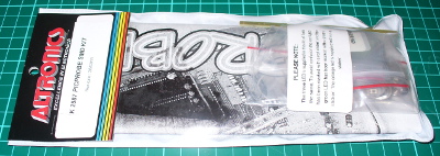
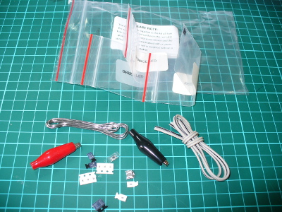
The kit is packaged in typical form, without any surprises:

kitpack

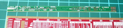
As mentioned earlier this kit is an interesting challenge due to the size of the PCB and the use of surface-mount components. The designer’s goal was to have the entire unit fit inside a biro housing (without the ink!). Thus the entire thing is using SMT parts.

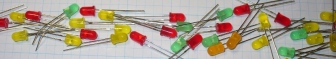
Thankfully the LEDs are packaged individually into labelled bags, as alone they’re identical to the naked eye. Although the kit wasn’t expensive, it would have been nice for one extra component of each type – beginners tend to lose the tiny parts. The cost could perhaps be offset by not including the usual solder which is too thick for use with the kit.

parts

Nevertheless with some care assembly can begin. After cleaning the PCB with some aerosol cleaner, it was tacked it to the desk mat to make life a little easier:

pcb

If you want one of those rulers – click here. Before building the kit it occurred to me that the normal soldering iron tip would be too large, so I ordered a tiny 0.2mm conical tip for the Hakko:

newtip

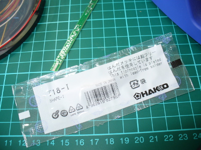
The tip on your average iron may be too large, so take this into account when trying to hand solder SMT components. The instructions include a guide on SMT hand-soldering for the uninitiated, well worth reading before starting.

Moving forward, soldering the parts was a slow and patient process. (With hindsight one could use the reflow soldering method to take care of the SMT and then carefully fit the links to the PCB). The instructions are quite good and include a short “how to solder SMT” guide, a PCB layout plan:

instructions

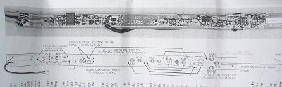
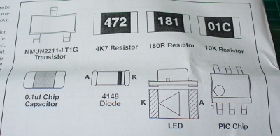
… along with an guide that helps identity the components:

instructionssmt

When soldering, make sure you have the time and patience not to rush the job. And don’t sneeze – after doing so I lost the PIC microcontroller for a few moments trying to find where it landed. Once the LEDs have been soldered in and their current-limiting resistors, it’s a good time to quickly test them by applying 5V and GND. I used the diode test feature of the multimeter which generates enough current to light them up.

Due to the PCB being single-sided (!) you also need to solder in some links. It’s best to do these before the button (and before soldering any other parts near the link holes), and run the wires beneath the top surface, for example:

links

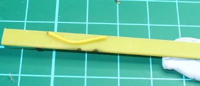
… and after doing so, you’ll need more blu-tack to hold it down!

gettingthere

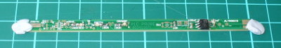
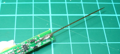
One of the trickiest parts of this kit was soldering the sewing needle at the end of the PCB to act as the probe tip – as you can see in the photo below, solder doesn’t take to them that well – however after a fair amount it does the job:

needle

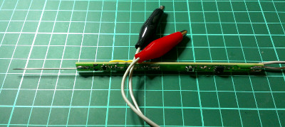
At this point it’s recommended you solder the wires to the PCB (for power) and then insert the probe into the pen casing. For the life of me I didn’t have a spare pen around here so instead we’re going to cover it in clear heatshrink. Thus leaving the final task as soldering the alligator clips to the power wires:

finished

Operation

What is a logic probe anyway? It shows what the logic level is at the probed point in a circuit. To do this you connect the black and red alligator clips to 0V and a supply voltage up to 18V respectively – then poke the probe tip at the point where you’re curious about the voltage levels. If it’s at a “high” state (on, or “1″ or whatever you want to call it) the red LED comes on.

If it’s “low” the green LED comes on. The third (orange) LED has two modes. It can either pulse every 50 mS when the logic state changes – or in “latch mode” it will come on and stay on when the mode changes, ideal for detecting infrequent changes in the logic state of the test point.

The kit uses a Microchip PIC12F20x microcontroller, and also includes the hardware schematic to make a basic RS232 PIC programmer and wiring instructions for reprogramming it if you want to change the code or operation of the probe.

Conclusion

The PIC Logic Probe is a useful piece of equipment if you want a very cheap way to monitor logic levels. It wasn’t the easiest kit to solder, and if Altronics revised it so the PCB was double-sided and changed the parts layout, there would be more space to solder some parts and thus make the whole thing a lot easier.

Nevertheless for under $17 it’s worth it. You can purchase it from Altronics and their resellers, or read more about it in the September 2007 edition of Silicon Chip. Full-sized images available on flickr. This kit was purchased without notifying the supplier. And if you made it this far – check out my new book “Arduino Workshop” from No Starch Press.

In the meanwhile have fun and keep checking into tronixstuff.com. Why not follow things on twitterGoogle+, subscribe  for email updates or RSS using the links on the right-hand column? And join our friendly Google Group – dedicated to the projects and related items on this website. Sign up – it’s free, helpful to each other –  and we can all learn something.


  • Newsletter

    Sign up for the PlanetArduino Newsletter, which delivers the most popular articles via e-mail to your inbox every week. Just fill in the information below and submit.

  • Like Us on Facebook