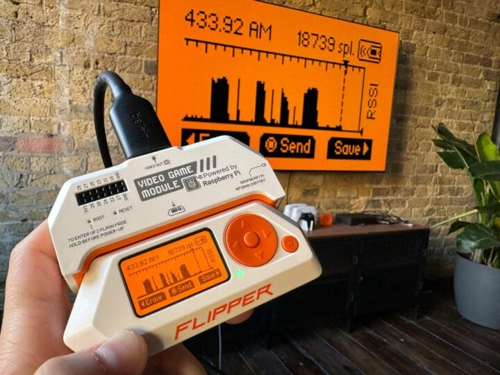
Flipper Zero hardware & wireless hacking tool can now be used as a proper game console thanks to a Raspberry Pi RP2040-powered video game module that mirrors the display of the device on a larger monitor or TV via DVI/HDMI video output, and also adds a 6-axis motion tracking sensor. The Flipper Zero has been in the news in recent days, notably with Canada’s government banning the device due to car theft (although it only seems feasible on older cars), and today the company has announced the launch of a video game module developed in collaboration with Raspberry Pi Ltd. Video game module specifications: MCU – Raspberry Pi RP2040 dual-core Arm Cortex-M0+ microcontroller clocked up to 133 MHz with 264 kB SRAM Video Output – DVI-D at 640х480 with 60 Hz refresh rate. It also supports HDMI. USB – USB Type-C port connected to the microcontroller. Acts as a USB device [...]
Creating a video signal from a computer, a job that once required significant extra hardware, is now a done deal with a typical modern microcontroller. We’ve shown you more NTSC, PAL, and VGA projects than you can shake a stick at over the years. Creating an HDMI video signal however is not so straightforward. It’s not a loosely defined analogue standard but a tightly controlled digital one upon which the clever hacks that eke full colour composite video from a single digital I/O pin will have little effect. Surely creating them from a simple microcontroller will be impossible! Not according to [techtoys], who has created an Arduino shield that creates an HDMI output from an SPI control input.
At its heart are two interesting integrated circuits that give us a little bit of insight into creating graphics at this level. First up is an RA8876 MIPI TFT controller which is a full graphics engine that produces a digital RGB output, followed by a CH7035B HDMI encoder that produces an HDMI output from the RGB. This combination of chips is particularly interesting one, because the RA8876 supports a variety of different interfaces that between them should be able to talk to most microcontrollers. In the Arduino world the only other HDMI options come via the use of an FPGA.
This is a project that seems to have been around for a couple of years, but which is still an active one. The classic Arduino shield form factor may now seem a little past its zenith, but as this board shows it’s still capable of being used for interesting new applications.
Amazon might not be happy about it, but at least part of the success of their Fire TV Stick was due to the large hacking and modification scene that cropped up around the Android-powered device. A quick search on YouTube for “Fire Stick Hack” will bring up a seemingly endless array of videos, some with millions of views, which will show viewers how to install unofficial software on the little media dongle. Now it looks like their latest media device, the Fire TV Cube, is starting to attract the same kind of attention.
The team at [Exploitee.rs] has recently taken the wraps off their research which shows the new Fire TV Cube can be rooted with nothing more than an Arduino and an HDMI cable you’re willing to cut apart. Of course, it’s a bit more complicated than just that, but between the video they’ve provided and their WiKi, it looks like all the information is out there for anyone who wants to crack open their own Cube. Just don’t be surprised if it puts you on the Amazon Naughty List.
The process starts by putting the device’s Amlogic S905Z into Device Firmware Upgrade (DFU) mode, which is done by sending the string “boot@USB” to the board over the HDMI port’s I2C interface. That’s where the HDMI cable comes in: you can cut into one and wire it right up to your Arduino and run the sketch [Exploitee.rs] has provided to send the appropriate command. Of course, if you want to get fancy, you could use an HDMI breakout board instead.
With the board in DFU mode in you gain read and write access to the device’s eMMC flash, but that doesn’t exactly get you in because there’s still secure boot to contend with. But as these things tend to go, the team was able to identify a second exploit which could be used in conjunction with DFU mode to trick the device into disabling signature verification. Now with the ability to run unsigned code on the Fire TV Cube, [Exploitee.rs] implemented fastboot to make it easier to flash their custom rooted firmware images to the hardware.
As with the Fire TV Stick before it, make sure you understand the risks involved when you switch off a device’s security features. They’re often there to protect the end user as much as the manufacturer.
High power of the UDOO “asks” for usage. One of many occasions to make it is to use various available periphery thus gaining a truly universal platform.
Favorite powerful embedded SBC called UDOO (S975-G000-2100-C2) already found many fans. Maybe also because of its compatibility with the Arduino Due platform (hardware and software) and mainly, it´s possible to connect it with various accessories. Thanks to a wide range of interfaces (USB, Ethernet, bluetooth, WiFi, …) is a connection of periphery flawless, what´s also a case of the 5MPx camera (autofocus).
Despite miniature dimensions this camera provides very decent resolution and speed – for example VGA (640×480) @90fps or 1080p @30fps, or QSXGA (2592×1944) @15fps. Also beneficial is recording of a video in a full 70°field of view (FOV).For a practical usage and application development with UDOO also serves the „Starter kit EU” containing an adapter for the third USB, RTC battery holder, HDMI cable with the UDOO logo, USB/ Micro USB Type B cable, SATA power supply cable, power supply adapter and an 8 GB micro SD card.
Perhaps the biggest “attraction” is the spacious 7“ display KIT LCD 7”–Touch 800×480 px RGB with a capacitive touch panel. By connecting of this display with the UDOO microcomputer, we get a ready-made platform usable to control various processes, with a power, which easily suits to majority of applications. Detailed information about the UDOO can be found in our article: Do you want a microcomputer which will „handle everything“?.
Planet Arduino is, or at the moment is wishing to become, an aggregation of public weblogs from around the world written by people who develop, play, think on Arduino platform and his son. The opinions expressed in those weblogs and hence this aggregation are those of the original authors. Entries on this page are owned by their authors. We do not edit, endorse or vouch for the contents of individual posts. For more information about Arduino please visit www.arduino.cc
You are currently browsing the archives for the HDMI category.