Media keyboards are nice in theory. But in practice they never have all the keys you want, and they almost always have a few you don’t. Sure, you could maybe reassign the ones you don’t use, but then the caps are wrong, and it’s a whole thing. So really, the only winning move is to make a micro macro keyboard as [littleSilvr] did to make all your shortcuts one-button accessible.
This lovely input has an Arduino Pro Micro for a brain, and Gateron browns for brawn. That knob there is a rotary encoder, not a potentiometer, because endless volume knob twiddling is just so much nicer. In case you’re wondering, those shortcuts open Fusion 360 and Cura, but we’re still not sure what the hyphen does.
Can we talk about those keycaps, though? [littleSilvr] used [Make Anything]’s process of of printing in multi-color with a single extruder. The technique involves building a vector for each color, each of which gets its own STL file. Then you add retraction as you go up through the layers, slow the print speed, change filament colors while the nozzle and bed are still warm, and voila, a vibrant canvas of colors.
Sometimes it’s necessary to make do with whatever parts one has on hand, but the results of squashing a square peg into a round hole are not always as elegant as [Juan Gg]’s programmable DC load with rotary encoder. [Juan] took a design for a programmable DC load and made it his own in quite a few different ways, including a slick 3D-printed enclosure and color faceplate.
The first thing to catch one’s eye might be that leftmost seven-segment digit. There is a simple reason it doesn’t match its neighbors: [Juan] had to use what he had available, and that meant a mismatched digit. Fortunately, 3D printing one’s own enclosure meant it could be gracefully worked into the design, instead of getting a Dremel or utility knife involved. The next is a bit less obvious: the display lacked a decimal point in the second digit position, so an LED tucked in underneath does the job. Finally, the knob on the right could reasonably be thought to be a rotary encoder, but it’s actually connected to a small DC motor. By biasing the motor with a small DC voltage applied to one lead and reading the resulting voltage from the other, the knob’s speed and direction can be detected, doing a serviceable job as rotary encoder substitute.
We’ve been told that standing at a desk is good for you, but unless you’re some kind of highly advanced automaton you’re going to have to sit down eventually no matter what all those lifestyle magazines say. That’s where desks like the IKEA SKARSTA come in; they use a crank on the front to raise and lower the desk to whatever height your rapidly aging corporeal form is still capable of maintaining. All the health benefits of a standing desk, without that stinging sense of defeat when you later discover you hate it.
But who wants to turn a crank with their hand in 2019? Certainly not [iLLiac4], who’s spent the last few months working in conjunction with [Martin Mihálek] to add some very impressive features to IKEA’s adjustable table. Replacing the hand crank with a motorized system which can do the raising and lifting was only part of it, the project also includes a slick control panel with a digital display that shows the current table height and even allows the user to set and recall specific positions. The project is still in active development and has a few kinks to work out, but it looks exceptionally promising if you’re looking to get a very capable adjustable desk without breaking the bank.
The heart of the project is a 3D printable device which uses a low-RPM DC gear motor to turn the hex shaft where the crank would normally go. A rotary encoder is linked to the shaft of the motor by way of printed GT2 pulleys and a short length of belt, which gives the system positional information and avoids the complexity of adding limit switches to the table itself.
For controlling the motor the user is given the option between using relays or an H-Bridge PWM driver board, but in either event an Arduino Nano will be running the show. In addition to controlling the motor and reading the output of the rotary encoder, the Arduino also handles the front panel controls. This consists of a TM1637 four digit LED display originally intended for clocks, as well as six momentary contact tactile switches complete with 3D printed caps. The front panel’s simple user interface not only allows for setting and recalling three preset desk heights, but can even be used to perform the calibration routine without having to go in and hack the source code to change minimum and maximum positions.
In the era of touch screens and capacitive buttons, we’d be lying if we said we didn’t have the occasional pang of nostalgia for the good old days when interfacing with devices had a bit more heft to it. The physical clunk and snap of switches never seems to get old, and while you can always pick up a mechanical keyboard for your computer if you want to hear that beautiful staccato sound while firing off your angry Tweets, there’s a definite dearth of mechanical interface devices otherwise.
[Jeremy Cook] decided to take matters into his own hands (literally and figuratively) by designing his own multipurpose USB rotary input device. It’s not a replacement for the mouse or keyboard, but a third pillar of the desktop which offers a unique way of controlling software. It’s naturally suited to controlling things like volume or any other variable which would benefit from some fine tuning, but as demonstrated in the video after the break even has some gaming applications. No doubt the good readers of Hackaday could think of even more potential applications for a gadget like this.
The device is built around the diminutive Arduino-compatible PICO board by MellBell, which features a ATmega32u4 and native USB. This allowed him to very rapidly spin up a USB Human Interface Device (HID) with minimal headaches, all he had to do was hang his buttons and rotary encoder on the PICO’s digital pins. To that end, he [Jeremy] used the fantastic I2C rotary encoder designed by [fattore.saimon], which readers may remember as a finalist in the Open Hardware Design Challenge phase of the 2018 Hackaday Prize. He also added a NeoPixel ring around the encoder to use for some visual feedback and because, well, it just looks cool.
Since all of the core components are digital, there’s not a whole lot required in the way of wiring or passive components. This let [Jeremy] put the whole thing together on a piece of perfboard, freeing him up to spend time designing the 3D printed enclosure complete with translucent lid so he can see the NeoPixel blinkenlights. He got the tolerances tight enough that the whole device can be neatly press-fit together, and even thought to add holes in the bottom of the case so he could push the perfboard back out if he needed to down the line.
[Jeremy] spends a good chunk of the video going over the software setup and development of the firmware, and details some of the nuances he had to wrap his head around when working with the I2C encoder. He also explains the math involved in getting his encoder to emulate a mouse cursor moving in a circle, which he thinks could be useful when emulating games that originally used an encoder such as Tempest or Pong.
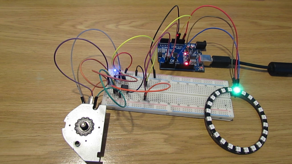
Stepper motors work by alternating a series of magnets in order to rotate its shaft by a certain angle. When the shaft is manually twisted, these magnets produce an electrical signal in a predictable pattern, which as shown in the video below, can be used as an encoder with the help of an Arduino Uno.
More information, including a circuit diagram and the Arduino code used for the stepper-NeoPixel and stepper-stepper examples can be found here. While the write-up notes that this stepper-encoder won’t work reliably if turned too slowly, it seems to work quite well at the fairly low speed shown in the demonstrations.
I want to tell you how to make incremental encoder from stepper motor. When we turning shaft of stepper motor it works like generator. It generates certain impulses on its coils. After some signal processing, we get same impulses as incremental encoder. This encoder has one problem, it can drop steps if you turning very slowly. But for many applications, it doesn’t matter.
We always think it is interesting that a regular DC motor and a generator are about the same thing. Sure, each is optimized for its purpose, but inefficiencies aside, you can use electricity to rotate a shaft or use a rotating shaft to generate electricity. [Andriyf1] has a slightly different trick. He shows how to use a stepper motor as an encoder. You can see a video of the setup below.
It makes sense. If the coils in the stepper can move the shaft, then moving the shaft should induce a current in the coils. He does note that at slow speeds you can miss pulses, however. Again, the device isn’t really optimized for this type of operation.
The circuit uses an opamp-based differential amplifier to read the pulses from the coil. Two opamps on two coils produce a quadrature signal just like a normal encoder. When the shaft turns in one direction, one pulse will lead the other. In the other direction, the lead pulse will be reversed.
There’s code to let an Arduino read the pulses, but we were disappointed it was behind a Patreon paywall. However, there’s plenty of code that will read quadrature on an Arduino or other processors, and that really isn’t the point of the post, anyway. We’ve seen similar hacks done with hard drive motors which are quite similar, by the way.
In a project, repetitive tasks that break the flow of development work are incredibly tiresome and even simple automation can make a world of difference. [Simon Merrett] ran into exactly this while testing different stepper motors in a strain-wave gear project. The system that drives the motor accepts G-Code, but he got fed up with the overhead needed just to make a stepper rotate for a bit on demand. His solution? A grbl man-in-the-middle jog pendant that consists of not much more than a rotary encoder and an Arduino Nano. The unit dutifully passes through any commands received from a host controller, but if the encoder knob is turned it sends custom G-Code allowing [Simon] to dial in a bit acceleration-controlled motor rotation on demand. A brief demo video is below, which gives an idea of how much easier it is to focus on the nuts-and-bolts end of hardware when some simple motor movement is just a knob twist away.
[Simon]’s jog pendant moves a single motor which is exactly what he needs to ease development of his 3D printed strain-wave gear using a timing belt, but it could be programmed with any G-Code at all. Speaking of DIY jog pendants for CNC machines, don’t forget this wireless one made from an Atari 2600 joystick that jogs a plasma cutter in X and Y, and zeroes it with a push of the button.
We’re digging these daisy-chainable encoders built by [fattore.saimon]. Each module consists of a rotary encoder attached to a PCB with a PIC16F15386 on the back. As we’ve covered in the past, the Microchip released their feature-rich PIC16 microprocessor just this year, and it’s great to see them start to crop up in projects. With 4 address jumpers on the back of each PCB, [fattore.saimon] is able to connect up to 16 of the encoders on the bus. The modules also have male and female plugs so he can connect them physically as well, to simplify wiring. Each module also has a PWMable bicolor LED for keeping track of each encoder’s setting.
[Patrick] was looking for an easier way to control music and movies on his computer from across the room. There is a huge amount of remote control products that could be purchased to do this, but as a hacker [Patrick] wanted to make something himself. He calls his creation, “Dial” and it’s a simple but elegant solution to the problem.
Dial looks like a small cylindrical container that sits on a flat surface. It’s actually split into a top and bottom cylinder. The bottom acts as a base and stays stationary while the top acts as a dial and a push button. The case was designed in SOLIDWORKS and printed on a 3D printer.
The Dial runs on an Arduino Pro mini with a Bluetooth module. The original prototype used Bluetooth 2.0 and required a recharge after about a day. The latest version uses the Bluetooth low energy spec and can reportedly last several weeks on a single charge. Once the LiPo battery dies, it can be recharged easily once plugged into a USB port.
The mechanical component of the dial is actually an off-the-shelf rotary encoder. The encoder included a built-in push button to make things easier. The firmware is able to detect rotation in either direction, a button press, a double press, and a press-and-hold. This gives five different possible functions.
[Patrick] wrote two pieces of software to handle interaction with the Dial. The first is a C program to deal with the Bluetooth communication. The second is actually a set of Apple scripts to actually handle interaction between the Dial and the various media programs on his computer. This allows the user to more easily write their own scripts for whatever software they want. While this may have read like a product review, the Dial is actually open source!
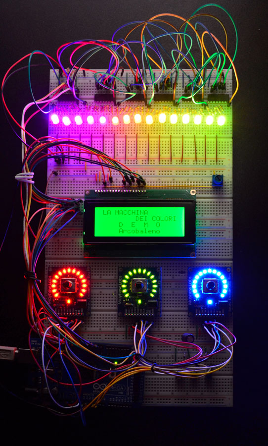
The Color Machine (La macchina dei colori, in Italian language) is a tool to teach children about the use and the operation of RGB color coding, which is used in all digital devices (TVs, smartphones, computers, etc.). It was created with Arduino Mega by an italian duo composed by Fabio Ghidini and Stefano Guerrini:
Using 3 knobs you can increase the percentages of red, green and blue separately, and the LED strip at the top of the machine lights up consistently with the color mix choosen.
The Color Machine has 4 different operating modes: “let’s create colors”, “guess the color”, “the names of the colors” and “demo”. Under the guidance of a teacher, children can play and learn at the same time to recreate colors with additive synthesis. This device is currently used in the educational workshops of Musil – Museum of Industry and Labour of Rodengo Saiano (Italy).
Planet Arduino is, or at the moment is wishing to become, an aggregation of public weblogs from around the world written by people who develop, play, think on Arduino platform and his son. The opinions expressed in those weblogs and hence this aggregation are those of the original authors. Entries on this page are owned by their authors. We do not edit, endorse or vouch for the contents of individual posts. For more information about Arduino please visit www.arduino.cc
You are currently browsing the archives for the rotary encoder category.

 The first thing to catch one’s eye might be that leftmost seven-segment digit. There is a simple reason it doesn’t match its neighbors: [Juan] had to use what he had available, and that meant a mismatched digit. Fortunately, 3D printing one’s own enclosure meant it could be gracefully worked into the design, instead of getting a Dremel or utility knife involved. The next is a bit less obvious: the display lacked a decimal point in the second digit position, so an LED tucked in underneath does the job. Finally, the knob on the right could reasonably be thought to be a rotary encoder, but it’s actually connected to a small DC motor. By biasing the motor with a small DC voltage applied to one lead and reading the resulting voltage from the other, the knob’s speed and direction can be detected, doing a serviceable job as rotary encoder substitute.
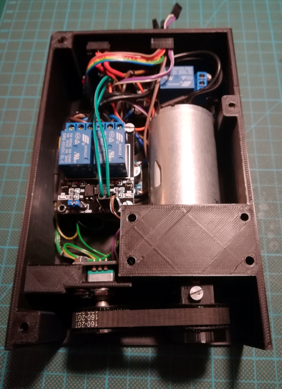

 In a project, repetitive tasks that break the flow of development work are incredibly tiresome and even simple automation can make a world of difference. [Simon Merrett] ran into exactly this while testing different stepper motors in a strain-wave gear project. The system that drives the motor accepts G-Code, but he got fed up with the overhead needed just to make a stepper rotate for a bit on demand. His solution? A