Posts | Comments

Planet Arduino

Archive for the ‘GPIO’ Category

flipper zero video game module

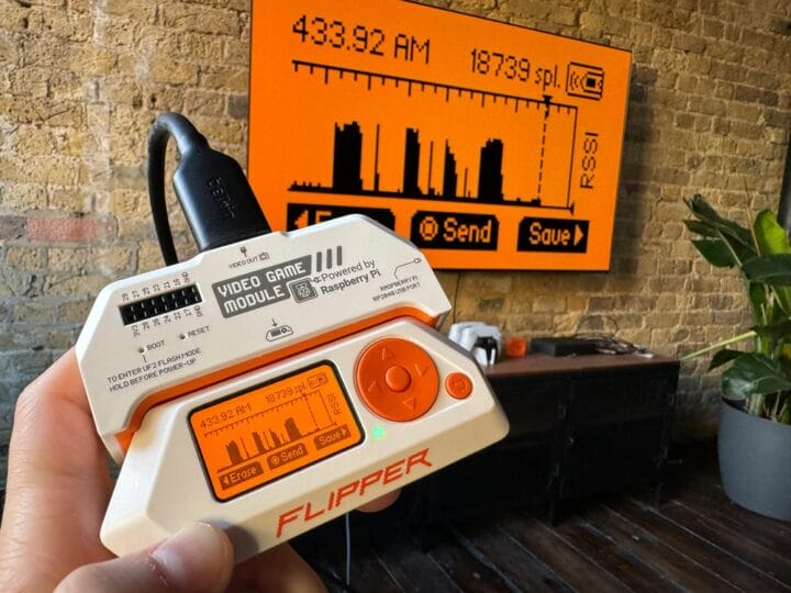
Flipper Zero hardware & wireless hacking tool can now be used as a proper game console thanks to a Raspberry Pi RP2040-powered video game module that mirrors the display of the device on a larger monitor or TV via DVI/HDMI video output, and also adds a 6-axis motion tracking sensor. The Flipper Zero has been in the news in recent days, notably with Canada’s government banning the device due to car theft (although it only seems feasible on older cars), and today the company has announced the launch of a video game module developed in collaboration with Raspberry Pi Ltd. Video game module specifications: MCU – Raspberry Pi RP2040 dual-core Arm Cortex-M0+ microcontroller clocked up to 133 MHz with 264 kB SRAM Video Output – DVI-D at 640х480 with 60 Hz refresh rate. It also supports HDMI. USB – USB Type-C port connected to the microcontroller. Acts as a USB device [...]

The post Flipper Zero gets a Raspberry Pi RP2040-powered video game module appeared first on CNX Software - Embedded Systems News.

We’re all familiar with the wide variety of Arduino development boards available these days, and we see project after project wired up on a Nano or an Uno. Not that there’s anything wrong with that, of course, but there comes a point where some hobbyists want to move beyond plugging wires into header sockets and build the microcontroller right into their project. That’s when one generally learns that development boards do a lot more than break the microcontroller lines out to headers, and that rolling your own design means including all that supporting circuitry.

To make that transition easier, [Sean Hodgins] has come up with a simple Arduino-compatible module that can be soldered right to a PCB. Dubbed the “HCC Mod” for the plated half-circle castellations that allows for easy soldering, the module is based on the Atmel SAMD21 microcontroller. With 16 GPIO lines, six ADCs, an onboard 3.3 V regulator, and a reset button, the module has everything needed to get started — just design a PCB with the right pad layout, solder it on, and surround it with your circuitry. Programming is done in the familiar Arduino IDE so you can get up and running quickly. [Sean] has a Kickstarter going for the modules, but he’s also releasing it as open source so you’re free to solder up your own like he does in the video below.

It’s certainly not the first dev module that can be directly soldered to a PCB, but we like the design and can see how it would simplify designs. [Sean] as shown us a lot of builds before, like this army of neural net robots, so he’ll no doubt put these modules to good use.

How do you tell how much load is on a CPU? On a desktop or laptop, the OS usually has some kind of gadget to display the basics. On a microcontroller, though, you’ll have to roll your own CPU load meter with a few parts, some code, and a voltmeter.

We like [Dave Marples]’s simple approach to quantifying something as complex as CPU load. His technique relies on the fact that most embedded controllers are just looping endlessly waiting for something to do. By strategically placing commands that latch an output on while the CPU is busy and then turn it off again when idle, a PWM signal with a duty cycle proportional to the CPU load is created. A voltage divider then scales the maximum output to 1.0 volt, and a capacitor smooths out the signal so the load is represented by a value between 0 and 1 volt. How you display the load is your own choice; [Dave] just used a voltmeter, but anything from an LED strip to some kind of audio feedback would work too.

Still just looking for a load meter for your desktop? Take your pick: an LED matrixold-time meters, or even Dekatrons.


Filed under: Arduino Hacks
Feb
06

Piconomic FW Library 0.4.2 released

ADC, arduino, arduino uno, ATmega328P, atmel, AVR, GPIO, i2c, Piconomic, SPI Comments Off on Piconomic FW Library 0.4.2 released 

tera_term_cli

by Pieter @ piconomic.co.za:

If you can beg, steal or borrow an Atmel ISP programmer, then you can use the Arduino environment to develop on the Atmel AVR Atmega328P Scorpion Board. An Arduino on Scorpion Board guide, Optiboot bootloader and example sketches have been added.

If you own an Arduino Uno board, you can now try out the Piconomic FW Library risk free without abandoning the creature comforts of the Arduino environment. You can use the existing Optiboot bootloader to upload code. I have added a getting started guide for the Arduino Uno. There are examples, including a CLI (Command Line Interpreter) Application that creates a “Linux Shell”-like environment running on the Arduino Uno so that you can experiment with GPIO, ADC, I2C and SPI using only Terminal software (for example Tera Term)… it is really cool!

Piconomic FW Library 0.4.2 released - [Link]


  • Newsletter

    Sign up for the PlanetArduino Newsletter, which delivers the most popular articles via e-mail to your inbox every week. Just fill in the information below and submit.

  • Like Us on Facebook