Posts | Comments

Planet Arduino

Archive for the ‘metronome’ Category

In the world of music, being able to keep time accurately is vital when playing a piece, as even small deviations in timing can cause the notes played to sound “off.” Ordinarily a device called a metronome is used to provide consistent ticks that the musician can use, but most are not that visually interesting. This is what inspired ChristineNZ over on Instructables to create her own metronome that uses an Arduino Uno to both show the beat and produce a small noise. 

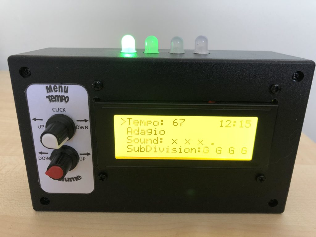
ChristineNZ’s Piano Metronome enables users to select both the rate (tempo) of the beat and its volume by turning one of two rotary encoders. Rather than having some clunky interface, this project has a large 20×4 I2C LCD on the front that displays the current time via an RTC, the sound’s amplitude, and even subdivisions. The top of the enclosure also holds four RGB LEDs that visually indicate the beat and subdivision if present.

One other cool feature of the Piano Metronome is its ability to show various tempo markings, which are the names given to the beats-per-minute value. To observe ChristineNZ’s project in action, check out the video below or visit its write-up to see how it was built along with the accompanying software.

The post The Piano Metronome is key to keeping the beat appeared first on Arduino Blog.

One of the features we wanted to add when re-designing the original metronome kit was to make it much easier for people to hack the kit, and add external connections. To this end, we added six header pin connections at the bottom of the circuit board:

ttm2_expansion_pins

The rest of this post will be an explanation of what each of those pins is doing.

  • Pin G – This pin is the ground connection, tied to the negative terminal of the battery holder. All signals are voltages measured relative to this ground.
  • Pin V – This pin is the voltage connection, tied to the positive terminal of the battery holder when the power switch is in the “on” position. This can be useful if you want to draw a bit of voltage to power your external hardware.
  • Pin B – This pin is the beat connection. The pin goes high (is equal to the V pin’s voltage) whenever the kit is beeping (for the duration of each beep). It outputs a solid (non-PWM) signal. This signal might be useful to trigger external lights or motors or sequencers or synthesizers, etc.
  • Pin X – This pin is a spare GPIO pin on the microcontroller, specifically it’s pin 3 named RA4. We didn’t have anything to use it for, but we added it to this header in case you want to hack the firmware to do something cool with it.
  • Pin S – This pin is the synchronize pin, which could someday be useful for connecting multiple metronomes together with a common timebase. We didn’t end up creating a way for you to connect multiple metronomes, but we thought it would be pretty cool to set one metronome going, then use the sync pins to allow the other metronomes to keep in sync with the “master” metronome started first. As it is, this pin is similar to the spare pin (labeled X), as it’s just connected to a GPIO pin on the microcontroller, specifically it’s pin 12 named RB5.
  • Pin P – This pin is the PWM output from the microcontroller that is used to drive the on-board piezo buzzer. If you want to make an external piezo beep, this is the pin for you, just connect the piezo between pin P and pin G (ground) and it should beep. The output signal is a 4 kHz square wave whenever the kit is beeping. If you want to disable the on-board piezo from beeping, check out the instructions here for which trace to cut.

Here’s a graphical explanation of the difference between the B “beat” and P “pwm_out” signals:

beat_vs_pwm

There are some more photos and information about external connections in the W&L Discussion forum.

You may also be interested in the circuit schematic (PNG).

Feb
13

Nightmare Metronome Reminds You That Time is Money

arduino, high voltage, metronome, music, Photography & Video Comments Off on Nightmare Metronome Reminds You That Time is Money 

spark1  TEMPO, TEMPO! is a piece of kinetic art in the form of a metronome with an audible spark. Or, according to creator Sanela Jahić, it’s “a kinetic object which form a narrative about accelerating the production process and enhancing work performance in order to increase competitiveness and improve profits.” […]

Read more on MAKE


  • Newsletter

    Sign up for the PlanetArduino Newsletter, which delivers the most popular articles via e-mail to your inbox every week. Just fill in the information below and submit.

  • Like Us on Facebook