Posts | Comments

Planet Arduino

Archive for the ‘3d print’ Category

I was intrigued by a recent project I saw that used two LED matrices placed diagonally to create an hourglass. The animated movement of the LEDs seemed a good simulation of the sand particles moving through the hourglass.

As is common, the project emphasized on how the hardware was wired together, which is trivial, without much explanation of its more challenging/interesting software aspects.

Additionally, most of the solutions I saw used an inertial position sensor to determine the position of the matrix, which seemed overkill for the simple functionality required.

So I decided to explore this topic and here is my solution.

Hourglass Basics

Hourglass

An hourglass (also known as a sand clock) is used to measure the passage of time. An hourglass is usually made up of two symmetric glass bulbs connected vertically by a narrow neck through which sand, or other suitable material, goes from the upper to the lower bulb under the action of gravity. The hourglass is turned upside-down to start another timer when all the sand runs into the bottom bulb.

Each hourglass is designed to measure a specific time interval – the time it takes to empty one bulb into the other. This time is regulated by factors that include the amount and size of the sand particles, the bulb size and the neck width.

Hardware Assembly

LED Matrices

The LED matrices are the commonly available 8×8 LED modules controlled by a MAX7219 controller. For this project the matrices with smaller PCBs that fit under the LED module are the best form factor.

Orientation Sensor

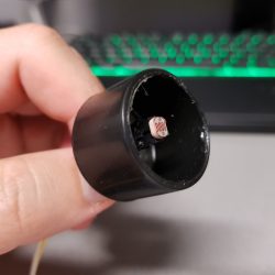
To keep things simple the orientation of the matrix is measured by a simple digital input wired to a tilt switch. These small and inexpensive sensors are available in many shapes and sizes, but all work similarly – a digital signal in one orientation and no signal for the opposite orientation, as shown in the figure below.

Internally the switch commonly has a metal ball that moves to make/break the electrical circuit.

This sensor is not able to detect intermediate states (eg, the hourglass on its side) but I am happy to live with that tradeoff compared to a much more expensive inertial sensor.

Hourglass Bezel

For testing purposes, using Fusion 360, I designed and 3D printed an hourglass shaped bezel to hold the 2 modules a jam fit.

This keeps the modules in the correct diagonal orientation with respect to each other and allows me to conveniently rotate the whole device easily.

Software Implementation

The software discussed in this section is available as the MD_MAX72xx_Hourglass example code with the MD_MAX72xx library.

Simulating the Hourglass

When thinking about this closed system, the top bulb can be considered a silo filled with sand with an exit at the bottom. As the sand passes through the neck, the sand particles above the moved particle also move into the void below and this is repeated all the way to the top of the sand reservoir.

As the mechanism is driven by gravity, it can be thought of as the particles trying to minimize their potential energy with respect to the hourglass neck.

Once the sand passes the neck it will fall (again trying to minimize the potential energy with respect to the base of the lower bulb) until it reaches the rest of the sand pile, at which time it will move over the surface of the existing pile trying to find its minimum energy state.

A good proxy for simulating the energy of each particle could be the distance between each particle and the neck/base, as potential energy is related to the height of each particle from the relevant ‘zero energy’ point.

Some Definitions

As these ‘zero energy’ point are points to which the particles are attracted, I decided to call them attractors in the software.

There are four attractors relevant to the simulation, shown in the figure at left, called HIHI, HI, LO, LOLO. When particles are travelling from the top to the bottom bulb, they are initially attracted to the HI attractor (the bottom of the top bulb) and then the LOLO attractor when they pass through the neck.

Conversely when the hourglass is turned over the attractors become the LO and HIHI attractors.

When wiring the matrices together, the module with the HI and HIHI attractor is module 0 (the first in the chain) and the other is module 1. The electrical connections are from the top to the bottom modules, as shown on the left.

Software Structure

There is a relatively simple structure to this software:

  1. Initialization (ie, the setup() function).
  2. Check if hourglass has changed orientation.
  3. At the appropriate time
    • Moving all the particles in both bulbs
    • Moving a particle from the upper to the lower bulb if one is ready to drop
    • Updating the matrices with the new arrangement

We’ll discuss each of these in turn below.

Data Structures and Static Data

Two simple data structures are defined to help manage the simulation.

The first is small container for the row and column coordinates of a LED ‘particle’.

typedef struct
{
  int8_t r, c;
} coord_t;

The next is the definition of a particle, which comprises its coordinates on the display and the attractor that is controlling its motion.

typedef struct
{
  attractorId_t att;
  coord_t p;
} particle_t;

The attractor enumerated type has the values as discussed earlier. The enumerated values are specifically nominated as they are used as the index into an array of constant coordinates for each of the attractors.

typedef enum 
{ 
  ATT_HIHI = 0,
  ATT_HI = 1,
  ATT_LO = 2,
  ATT_LOLO = 3
} attractorId_t;

Finally, an enumerated type is defined to track the current orientation of the hourglass (ie, the direction in which the particles are flowing due to the action of gravity).

// flow direction for particles (HI->LO or LO->HI)
typedef enum 
{ 
  FLOW_HI2LO, 
  FLOW_LO2HI 
} flowDirection_t;

Initialization

The particle array is statically initialized when it is declared. As the matrix is on the diagonal corner, this seemed an easier way to get a specific pattern in the top bulb at the start.

The normal hardware initialization happens in setup(), and the display is updated with the starting particle arrangement.

Check Hourglass Orientation

The hourglass orientation is given by a simple digital input from the tilt sensor. When that input changes it needs to be processed into a direction indicator (FLOW_* enumerated value) and a different attractor (ATT_*) for each particle.

For example, if a particle is in the top bulb, travelling FLOW_HI2LO directions, is currently attracted to ATT_HI. Once the flow is reversed (to FLOW_LO2HI) that particle is now attracted to HIHI.

Moving Particles

Particle moves occur periodically, controlled by the total timer duration, 30 seconds for the example code. Given that all the particles need to transition to the next bulb by the end of the period, each time slice is a total time divided by the number of particles.

For each particle, each of the 8 points surrounding the particle need to be tested to see if the particle should move into that location. A particle can move into a new location if:

  1. The location is unoccupied.
  2. The location is within the bounds of the hourglass bulb containing the particle.
  3. The distance to the particle’s attractor is the minimum distance of the current set of potential locations.

The distance between the particle and its attractor is the length of the line segment that connects the two points, given by d=√((r2 – r1)² + (c2 – c1)²). As d is just for comparison the square root is unnecessary and the software uses d².

If two or more points are found to be equal minima, then a random choice is made between them.

Transition Particles

Once all the particles have moved, a special check is made to see if a particle is at the ATT_HI or ATT_LO points (depending on the flow direction).

If one is found, it is moved to the top of the lower bulb if there is no other particle there and its attractor is changed so that it travels to the bottom of the hourglass.

Display Update

The display update clears the display and then redraws all the particles at their current coordinates.

So does it work?

Given the simplicity of the approach and simulation code, the LED hourglass display looks good and works surprisingly well.

A cat skull enclosed in a domed security camera enclosure with green LEDs illuminating the eye sockets, sitting on a table with other skulls and rocks.

[Emily Velasco] has an internet provider that provides sub-par connectivity. Instead of repeatedly refreshing a browser tab to test if the network is up, [Emily] decided to create an internet status monitor by embedding indicator lights in a cat skull…for some reason.

The electronics are straightforward, with the complete parts list consisting of an Arduino Nano 33 IoT device connected to a pair of RGB LEDs and 50 Ohm resistors. The Nano attempts to connect to a known site (in this case, the Google landing page) every two seconds and sets the LEDs to green if it succeeds or red if it fails.

The cat skull is thankfully a replica, 3D printed by one of [Emily]’s Twitter acquaintances, and the whole project was housed in a domed security camera enclosure. [Emily] mounts the LEDs into the skull to create a “brain in a jar” effect.

The source is available on GitHub for those wanting to take a look. We’ve featured internet connectivity status indicators in the form of traffic lights here before, as well as various network status monitors and videoconferencing indicator lights.

We’re all familiar with the experience of buying hobby servos. The market is awash with cheap clones which have inflated specs and poor performance. Even branded servos often fail to deliver, and sometimes you just can’t get the required torque or speed from the small form factor of the typical hobby servo.

Enter [James Bruton] and his DIY RC servo from a windscreen wiper motor. Windscreen wiper motors are cheap as chips, and a classic salvage. The motor shaft is connected to a potentiometer via a pulley and some string, providing the necessary closed-loop feedback. Instead of using the traditional analog circuitry found inside a servo, an Arduino provides the brains. This means PID control can be implemented on the ‘duino, and tuned to get the best response from different load characteristics. There’s also the choice of different interfacing options: though [James]’ Arduino code accepts PWM signals for a drop-in R/C servo replacement, the addition of a microcontroller means many other input signal types and protocols are available. In fact, we recently wrote about serial bus servos and their numerous advantages.

We particularly love this because of the price barrier of industrial servomotors; sure, this kind of solution doesn’t have the precision or torque that off-the-shelf products provide, but would be sufficient for many hacks. Incidentally, this is what inspired one of our favourite open source projects: ODrive, which focuses on harnessing the power of cheap brushless motors for industrial use.

Connecting your shiny new ESP8266 to WiFi can be as simple or as complicated as you please. Most people decide to manually add it. Some people find clever ways to make the bloody thing connect itself. [Eduardo Zola] transfers his WiFi password using the flashing light of a smartphone screen.

A simple photo-resistor and a bit of tinkering allows him to easily send credentials — or any data really — to his ESP8266, through the power of LiFi. Short for Light Fidelity, LiFi transmits data using light with on and off states representing digital values. It can use visible light, or reach into either the ultraviolet or infra-red radiation if need be. For the nitty-gritty details on the subject, check out our primer on LiFi.

 A flashing LCD screen and a photo-resistor barely make the cut for a one-way LiFi system, but [Eduardo Zola] makes it work. The approach is to build a resitor divider and watch an input pin on the ESP for changes.

The trick is to keep ambient light out of the mix. The test sensor shown here places the LDR in a black cap, but [Eduardo] 3D-Printed a slick little enclosure for his reverse flashlight so it fits flush with the phone screen. One click and about half a minute of a flashing screen later, and the Wi-Fi credentials are transferred. This circuit could really be added onto any project, for short data transfers. With a bit more work on the sensor circuit, speed could be improved with the limiting factor being the timing on the phone screen itself.

Since the ESP8266 has its own WiFi connection, it’s likely you’ll use that for data transfer once the LiFi gets it onto the network. But any situation where you don’t have a full user input or a network connection could benefit from this. Pull out that old scrolling LED matrix project and add this as a way to push new messages to the device!

If you have OCD, then the worst thing someone could do is give you a bowl of multi-coloured M&M’s or Skittles — or Gems if you’re in the part of the world where this was written. The candies just won’t taste good until you’ve managed to sort them in to separate coloured heaps. And if you’re a hacker, you’ll obviously build a sorting machine to do the job for you.

Use our search box and you’ll find a long list of coverage describing all manner and kinds of sorting machines. And while all of them do their designated job, 19 year old [Willem Pennings]’s m&m and Skittle Sorting Machine is the bees knees. It’s one of the best builds we’ve seen to date, looking more like a Scandinavian Appliance than a DIY hack. He’s ratcheted up a 100k views on Youtube, 900k views on imgur and almost 2.5k comments on reddit, all within a day of posting the build details on his blog.

As quite often happens, his work is based on an earlier design, but he ends up adding lots of improvements to his version. It’s got a hopper at the top for loading either m&m’s or Skittles and six bowls at the bottom to receive the color sorted candies. The user interface is just two buttons — one to select between the two candy types and another to start the sorting. The hardware is all 3D printed and laser cut. But he’s put in extra effort to clean the laser cut pieces and paint them white to give it that neat, appliance look. The white, 3D printed parts add to the appeal.

Rotating the input funnel to prevent the candies from clogging the feed pipes is an ace idea. A WS2812 LED is placed above each bowl, lighting up the bowl where the next candy will be ejected and at the same time, a WS2812 strip around the periphery of the main body lights up with the color of the detected candy, making it a treat, literally, to watch this thing in action. His blog post has more details about the build, and the video after the break shows the awesome machine in action.

And if you’re interested in checking out how this sorter compares with some of the others, check out these builds — Skittles sorting machine sorts Skittles and keeps the band happy, Anti-Entropy Machine Satiates M&M OCD, Only Eat Red Skittles? We’ve Got You Covered, and Hate Blue M&M’s? Sort Them Using the Power of an iPhone!  As we mentioned earlier, candy sorting machines are top priority for hackers.

[via r/electronics]


Filed under: Arduino Hacks, cooking hacks

The clever folks over at [Novaetech SRL] have unveiled openQCM, their open-source quartz crystal microbalance. A QCM measures very minute amounts of mass or mass variation using the piezoelectric properties of quartz crystal. When an object is placed on the surface of this sensor, the changes in the crystal’s resonant frequency can be detected and used to determine its mass in a variety of experimental conditions (air, vacuum, liquid). However, most QCM technology is proprietary and pricey – at least US$3000 for the microbalance itself. Any consumables, such as additional crystals, cost several hundred dollars more.

The openQCM has a sensitivity of 700 picograms. At its core is an Arduino Micro with a custom PCB. The board contains a 10K thermistor for temperature offset readings and the driver for a Pierce oscillator circuit. The quartz crystal frequency is determined by hacking the timer interrupts of the Arduino’s ATmega32u4. An external library called FreqCount uses the clock to count the number of pulses of the TTL signal in a 1 second time frame. This yields quartz crystal frequency resolution of 1Hz. The user interface is built in Java so that data can be read, plotted, and stored on your computer. The entire casing is 3D-printed, and it appears that the sensors are standard oscillator crystals without their cases.

Simplistic design makes assembly and maintenance a breeze. It only weighs 55 grams. Replacing the quartz crystal requires no special tools due to the clip system. The openQCM can be used as a single unit, or in multiples to form a network for all of your precise measurement needs. While they have kits available that will set you back US$500, all of the files and schematics for 3D-printing, assembly, and the PCB are available on the openQCM site for free.

[Special Thanks to Augustineas for sending us this tip!]


Filed under: Arduino Hacks, chemistry hacks


  • Newsletter

    Sign up for the PlanetArduino Newsletter, which delivers the most popular articles via e-mail to your inbox every week. Just fill in the information below and submit.

  • Like Us on Facebook