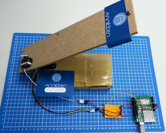
Jonathan from Anikken wrote us to show how Andee is more than just a Bluetooth shield. Not only does it allow to wirelessly connect and control the Arduino from any Android phone, but it comes with its own library for the Arduino IDE, to easily customise the smartphone user interface by doing the coding in the Arduino IDE itself without any Android programming.
He then created some action with it producing a Rubber band launcher and a cool video to see how it works:
I got the inspiration to build this rubber band launcher after watching a video of a rubber band gattling gun. I originally intended to build a rubber band gattling gun turret that I can control with my smartphone using stuff that I could find in my home and office.
Unfortunately, I didn’t have enough materials lying around to get it done. Instead, using whatever I had, I improvised and made a simpler version – the Rubber Band Launcher Mark I. (I’m calling it Mark I because I’m in the process of upgrading this model).
The launcher was built using some plywood, cardboard, cable ties, some screws, two servos, the Arduino Uno, and the Annikken Andee.
He started with a piece of plywood that he found in his office, he cut it up and mounted two servos to it using screws and cable ties : one servo controls the firing of the rubber band, the other controls the up/down movement. He then mounted the machine onto a cardboard box filled it with heavy objects to prevent the launcher from topping over.
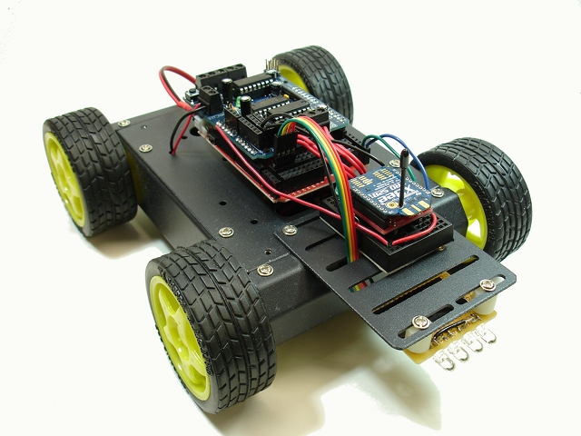
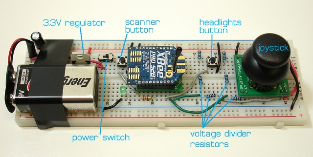
In his blog, Michael describes a nice 4WD robot he realized by means of an arduino-compatible board, a motor shield and a couple of XBee radios, which have been used to implement a simple and effective remote control.
Actually, the remote is made up of a standard breadboard equipped with a joystick, a couple of buttons (that can turn the robot in a Kitt-like vehicle!) and the XBee radio. One interesting feature of this project is that the remote controller is fairly simple and has been designed to work with just the XBee radio board, instead of requiring an additional MCU.
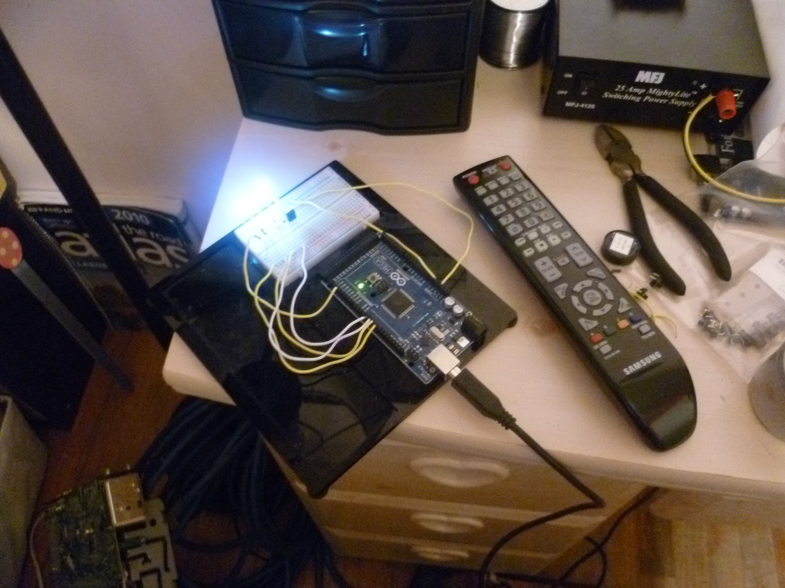
This is a good example of hacking devices with Arduino. [sspence65] has put on oa good tutorial to start from something easy and simple: IR hack.
Capturing codes from any tv remote, and using them to control devices attached to Arduino Outputs. Press a button on a TV Remote, and the code appears in the serial monitor, Add that code to the case/switch statements in the sketch to control an output pin.
On the [website] there is the full explanation and code to build the same experience, but nothing prevent you to implement a custom way for your IR devices.
In this article we’re going to look at controlling relays over the Internet. In doing so you will then be able to turn almost anything on and off as long as you have http access on an Internet-enabled device. Why would you want to do this? Connect an outdoor light – and turn it on before arriving home. Control the power to your TV setup – then you can control childrens’ TV viewing at a whim. Control farm water pumps without getting out of the truck. We’ll break this down into two stages. First we’ll explain how the RELAY8: relay control shield works and control it locally, then control it remotely using the teleduino service. We will be using Arduino IDE v1.0.1.
This tutorial will assume you have an understanding from three other articles – so please have a quick read of I2C bus, the MCP23017 I/O expander and teleduino. But don’t panic – we’ll try and keep it simple here.
Using the RELAY8: you can control eight relays using the I2C bus and the MCP23017 I/O expander – which saves your digital outputs for other purposes. There are three hardware settings you need to consider when using the shield:
Power – how will you power the relay coils?
You can directly connect between 5 and 24V DC using the terminal block on the right-hand side of the shield – great for stronger relay coils.
You can power the relay coils using power from the Arduino. So whatever power is going to the Arduino Vin can power the shield. To do this jumper the two pins next to the Vin shield connector. In doing so – you must check that the combined current draw of all your relays on at once will not exceed what is available to the Arduino. Usually OK when using solid-state relays, as most examples use around 15mA of current to activate. However double-check your relay specifications before doing so.
You can also power the Arduino board AND the shield by feeding in external power to the shield and jumpering the two pins described above
Which I2C address to use for each shield? By default it is 0×20. However you can alter the last three bits of the address by changing the jumpers at the bottom-left of the shield. Each jumper represents one bit of the bus address – no jumper means zero, and a jumper means one. So if you jumper ADDR0, the address will be 0×21 – etc. Using this method you can then stack up to eight shields – and control 64 relays!
Are you using an Arduino Leonardo board? If so – your shield I2C pins aren’t A4/A5 – they’re over near the top of the board:
However this isn’t a problem. Solder in some header pins to the shield’s SCL/SDA holes (next to AREF). Then turn over the RELAY8: board and you will see some solder pads as shown below. With a thin knife, cut the copper tracks shown with the blue lines:
Doing this will redirect the I2C bus from the microcontroller to the correct pins at the top-left. Once you have decided on your power and I2C-bus options, it’s time to connect the relays. Doing so is simple, just connect the + and – from the relay coil to the matching position on your RELAY8: shield, for example:
Today we’re just using prototyping wires, so when creating a permanent installation ensure the insulation reaches the terminal block. When working with relays you would use a diode across the coil to take care of back-EMF – however the shield has this circuitry, so you don’t need to worry about that at all. And if you’re wanting to control more than one shield – they stack nicely, with plenty of clearance between shields, for example:
Now to test the shield with a quick demonstration. Our sketch will turn on and off each relay in turn. We use the addressing format described in table 1.4 of the MCP23017 data sheet, The relays 1 to 8 are controlled by “bank A” of the MCP23017 – so we need to set that to output in our sketch, as shown below:
// Example 47.1
#include "Wire.h" // for I2C bus
#define I2C_ADDR 0x20 // 0x20 is the address with all jumpers removed
void setup()
{
 Wire.begin(); // Wake up I2C bus
 // Set I/O bank A to outputs
 Wire.beginTransmission(I2C_ADDR);
 Wire.write(0x00); // IODIRA register
 Wire.write(0x00); // Set all of bank A to outputs
 Wire.endTransmission();
}
int period = 500;
void loop()
{
 byte relay = 1;
 for (int i=1; i<9; i++)
 {
 // turn on relay
 Wire.beginTransmission(I2C_ADDR);
 Wire.write(0x12); // Select bank A
 Wire.write(relay); // Send value to bank A
 Wire.endTransmission();
 delay(period);
// turn off all relays
 Wire.beginTransmission(I2C_ADDR);
 Wire.write(0x12); // Select bank A
 Wire.write(0); // Send value to bank A
 Wire.endTransmission();
 delay(period);

 relay = relay * 2; // move to next relay
 }
}
The sketch simply sends the values of 1, 2, 4, 8, 16, 32, 64 and 128 to the shield – each value in turn represents relays 1 to 8. We send 0 to turn off all the relays. Here’s a quick video showing it in action – the LEDs on the shield show the relay coil power status:
Now there is one small caveat – every time you send a new command to the MCP23017, it overwrites the status of the whole bank of pins. For example if relay 3 is on, and we send the value 2 – this will turn on relay 2 and turn off 3. Why? Because the values are converted to binary when heading down to the relay shield. So if we send 1, in binary this is:
00000001
which turns on relay 1 – and turns off relays 2 to 7. But then if we send 4 to turn on relay 3, in binary this is:
00000100
which turns on relay 3, but turns off relays 1, 2, and 4 to 8. So how do we turn on or off all eight relays at once? Just do a little binary to decimal conversion. Let’s say you want relays 1, 3, 5 and 7 on – and 2, 4, 6 and 8 off. In binary our command value would be:
01010101
and in decimal this is 85. Want to turn them all on at once? Send 255. Then all off? Send zero.
Now let’s do it via the Internet…
You’re going to need an Ethernet-enabled Arduino board. This could involve adding an Ethernet shield to your existing board, or using an all-in-one board like the Freetronics EtherTen. We will now use the teleduino service created by Nathan Kennedy to send commands to our Arduino boards via the Internet. At this point, please review and understand the teleduino article – then, when you can successfully control a digital output pin – return here to continue.
First, get the hardware together. So ensure your relay shield is in the Arduino and you have uploaded the
TeleduinoEthernetClientProxy.ino
sketch. For the first couple of times, it’s good to still have the teleduino status LED connected – just to keep an eye on it. Plug your Arduino into your router and the power. After it connects to teleduino (four blinks of the status LED) we have to send three commands via http. The first tells teleduino that we’re sending I2C commands. You only do this once after every Arduino reset or power-up situation. It is:
At this stage the relay shield is now ready to accept your bytes to turn on and off the outputs. Again, just like the sketch – we send two bytes. For example:
turns on all the outputs – however with the URL we need to send the byte representing the outputs in hexadecimal. So 255 is FF, 0 is 0, etc. For example to turn them all off, use:
Simple. You can simply bookmark your URLs for later use as well – and don’t forget to use a URL-shortener such as bit.ly to makes things simpler for you.
Conclusion
Now you have a way to control many relays either locally or remotely over the Internet. I hope you found this article useful or at least interesting. If you have any suggestions for further articles (and not thinly-veiled methods of asking me to do your work for you…) – email them to john at tronixstuff dot com. Thanks to Freetronics for the use of their hardware and Nathan Kennedy for teleduino, his support and advice.
Have fun and keep checking into tronixstuff.com. Why not follow things on twitter, Google+, subscribe for email updates or RSS using the links on the right-hand column, or join our Google Group – dedicated to the projects and related items on this website. Sign up – it’s free, helpful to each other – and we can all learn something.
Recently a new method of interacting with an ethernet-enabled Arduino board and the Internet was brought to my attention – a new system called Teleduino. In this article we test a few of the basic features and see what is possible. Please note that these are my own experiments and that Teleduino is a work in progress. So follow along and see for yourself.
Getting Started
You will need an Arduino Uno (or compatible) board and Ethernet shield with the Wiznet chip – or a Freetronics EtherTen (a much neater solution). At this stage Teleduino doesn’t support other boards such as the Mega.
Download and install the Teleduino Arduino library. This is available from the resources section of the home page. You will also need to be running Arduino IDE v1.0 or greater.
Request an API key. This identified your particular Arduino from the rest.
Get together some basic electronics components for testing, such as some LEDs and 560R resistors; sources of analog input such as an LDR or TMP36 temperature sensor; and a solderless breadboard.
Don’t forget the ethernet cable from your Arduino stack to the router!
Finally, some rudimentary knowledge about networking will be useful. (IP address, DHCP, etc.)
The Teleduino system uses pin D8 for a status LED, so you may find connecting one up now useful while experimenting. Connect as such:
Controlling digital outputs
In this example we control an LED, turning it on and off. For demonstration purposes, connect another LED with a resistor to D6 in the same method as shown above. Next, you need to upload a sketch to the Arduino. It is the
TeleduinoEthernetClientProxy.ino
which is included with the library examples. Before uploading, you need to make some modifications. The first of these is to add your API key. Go back to the email you received from Teleduino, and click on the link provided. It will take you to a website that shows a byte array variable named byte key[]. You will copy this into the sketch, replacing the same array full of hexadecimal zeros in the sketch – as shown below – with your own:
… and change one of the hexadecimal numbers to 0×00… just in case there is a clash with other addresses on your network. You never know. Finally – depending on your network router, you may need to manually allocate the IP address for your Ethernet shield and/or set the DNS server to use. To do this, scroll down to
// User configurable variables
where you can change the useDHCP and/or useDNS variables to false, and update those values below. However if you’re not sure, just leave them be unless you need to change them. Finally – upload the sketch to your Arduino, get the hardware together and plug it into the network.
Watch your status LED – it will blink a number of times, depending on the status of things. The blink levels are:
1 blink – initialising
2 blinks – starting network connection
3 blinks – connecting to the Teleduino server
4 blinks – authentication successful
5 blinks – session already exists for supplied key (sometimes happens after a quick restart – will work on next auto-restart)
6 blinks – Invalid or unauthorised key – check your API key is correctly entered in the sketch as described earlier
10 blinks – connection dropped
If all is well, after a minute yours should be on blink level 4, then it will idle back to blink level 1. Now to test the connection with our first command.
You send commands to the Arduino using a set of URLs that will contain various parameters. You will need your API key again for these URLs which is then inserted into the URL. The first will report the version of software on the Arduino. Send
however replace 999999 with your API key (and in all examples shown here). If successful, you should see something similar to the following in the web browser:
However if something is wrong, or there are connection difficulties you will see something like:
Before using digital outputs, and after every reset of the Arduino) you need to set the pin mode for the digital output to control. In our example, we use:
Note that the pin number and mode are set with single digits, as you can see above this is for pin 6, and we use mode=1 for output. You should save this as a bookmark to make life easer later on. When the command has been successfully sent, a message will be shown in the webpage, for example:
Moving forward – you turn the digital output on with the following:
and to turn it off, set the final part of the URL to
output=0
Easy. How did you go? It really is amazing to see it work. Now you can control your Arduino from almost anywhere in the world. Again, saving these as bookmarks to make things easier, or a URL shortening service.
At this point you should now have the gist of the Teleduino service and how it is operated.
There is so much more you can do, and currently the list includes (From the author):
Reset, ping, get version, get uptime, get free memory.
Define pin modes, set digital outputs, set analog outputs, read digital inputs, read analog inputs, or read all inputs with a single API call.
Define up to 2 ‘banks’ of shift registers. Each ‘bank’ can contain up to 32 cascaded shift registers, giving a total of 512 digital outputs.
Shift register outputs can be set, or merged, and expire times can be set on merges (you could set an output(s) high for X number of milliseconds).
Define, and read and write from serial port.
Read and write from EEPROM.
Define and position up to 6 servos.
Set preset values for the above functions, which get set during boot. Preset values are stored in the first 160ish bytes of the EEPROM.
For more information check the Teleduino web site, and further tutorials can be found here. Here is a simple example of Teleduino at work – controlling a light switch:
Conclusion
At this moment Teleduino is simple, works and makes a lot of ideas possible. We look forward to making more use of it in future projects, and hope you can as well. Kudos to Nathan Kennedy, and we look forward to seeing Teleduino advance and develop over the future. If all this Arduino is new to you, check out the tutorials. Thanks to Freetronics for the use of their Ethernet-enabled hardware.
In the meanwhile have fun and keep checking into tronixstuff.com. Why not follow things on twitter, Google+, subscribe for email updates or RSS using the links on the right-hand column? And join our friendly Google Group – dedicated to the projects and related items on this website. Sign up – it’s free, helpful to each other – and we can all learn something.
Recently a new method of interacting with an ethernet-enabled Arduino board and the Internet was brought to my attention – a new system called Teleduino. In this article we test a few of the basic features and see what is possible. Please note that these are my own experiments and that Teleduino is a work in progress. So follow along and see for yourself.
Getting Started
You will need an Arduino Uno (or compatible) board and Ethernet shield with the Wiznet chip – or a Freetronics EtherTen (a much neater solution). Teleduino now supports Arduino Mega and the awesome EtherMega.
Download and install the Teleduino Arduino library. This is available from the resources section of the home page. You will also need to be running Arduino IDE v1.0 or greater.
Request an API key. This identified your particular Arduino from the rest.
Get together some basic electronics components for testing, such as some LEDs and 560R resistors; sources of analog input such as an LDR or TMP36 temperature sensor; and a solderless breadboard.
Don’t forget the ethernet cable from your Arduino stack to the router!
Finally, some rudimentary knowledge about networking will be useful. (IP address, DHCP, etc.)
The Teleduino system uses pin D8 for a status LED, so you may find connecting one up now useful while experimenting. Connect as such:
Controlling digital outputs
In this example we control an LED, turning it on and off. For demonstration purposes, connect another LED with a resistor to D6 in the same method as shown above. Next, you need to upload a sketch to the Arduino. It is the
which is included with the library examples. Before uploading, you need to make some modifications. The first of these is to add your API key. Go back to the email you received from Teleduino, and click on the link provided. It will take you to a website that shows a byte array variable named byte key[]. You will copy this into the sketch, replacing the same array full of hexadecimal zeros in the sketch – as shown below – with your own:
Next, scroll down to
… and change one of the hexadecimal numbers to 0×00… just in case there is a clash with other addresses on your network. You never know. Finally – depending on your network router, you may need to manually allocate the IP address for your Ethernet shield and/or set the DNS server to use. To do this, scroll down to
where you can change the useDHCP and/or useDNS variables to false, and update those values below. However if you’re not sure, just leave them be unless you need to change them. Finally – upload the sketch to your Arduino, get the hardware together and plug it into the network.
Watch your status LED – it will blink a number of times, depending on the status of things. The blink levels are:
1 blink – initialising
2 blinks – starting network connection
3 blinks – connecting to the Teleduino server
4 blinks – authentication successful
5 blinks – session already exists for supplied key (sometimes happens after a quick restart – will work on next auto-restart)
6 blinks – Invalid or unauthorised key – check your API key is correctly entered in the sketch as described earlier
10 blinks – connection dropped
If all is well, after a minute yours should be on blink level 4, then it will idle back to blink level 1. Now to test the connection with our first command.
You send commands to the Arduino using a set of URLs that will contain various parameters. You will need your API key again for these URLs which is then inserted into the URL. The first will report the version of software on the Arduino. Send
however replace 999999 with your API key (and in all examples shown here). If successful, you should see something similar to the following in the web browser:
However if something is wrong, or there are connection difficulties you will see something like:
Before using digital outputs, and after every reset of the Arduino) you need to set the pin mode for the digital output to control. In our example, we use:
Note that the pin number and mode are set with single digits, as you can see above this is for pin 6, and we use mode=1 for output. You should save this as a bookmark to make life easer later on. When the command has been successfully sent, a message will be shown in the webpage, for example:
Moving forward – you turn the digital output on with the following:
and to turn it off, set the final part of the URL to
Easy. How did you go? It really is amazing to see it work. Now you can control your Arduino from almost anywhere in the world. Again, saving these as bookmarks to make things easier, or a URL shortening service.
At this point you should now have the gist of the Teleduino service and how it is operated.
There is so much more you can do, and currently the list includes (From the author):
Reset, ping, get version, get uptime, get free memory.
Define pin modes, set digital outputs, set analog outputs, read digital inputs, read analog inputs, or read all inputs with a single API call.
Define up to 2 ‘banks’ of shift registers. Each ‘bank’ can contain up to 32 cascaded shift registers, giving a total of 512 digital outputs.
Shift register outputs can be set, or merged, and expire times can be set on merges (you could set an output(s) high for X number of milliseconds).
Define, and read and write from serial port.
Read and write from EEPROM.
Define and position up to 6 servos.
Set preset values for the above functions, which get set during boot. Preset values are stored in the first 160ish bytes of the EEPROM.
At this moment Teleduino is simple, works and makes a lot of ideas possible. We look forward to making more use of it in future projects, and hope you can as well. Kudos to Nathan Kennedy, and we look forward to seeing Teleduino advance and develop over the future. If all this Arduino is new to you, check out the tutorials. Thanks to Freetronics for the use of their Ethernet-enabled hardware.
In the meanwhile have fun and keep checking into tronixstuff.com. Why not follow things on twitter, Google+, subscribe for email updates or RSS using the links on the right-hand column? And join our friendly Google Group – dedicated to the projects and related items on this website. Sign up – it’s free, helpful to each other – and we can all learn something.
This chapter we will examine piezo buzzers, continue with our alarm clock, and then spend more time with the wireless radio modules by creating some remote control systems and sending various data over the airwaves. So let’s go!
Sometimes you would like to make some noise. For warnings, fun, or to annoy people. A very simple and inexpensive way to do this is with a piezoelectric buzzer. In simple terms, it contains a disc of metal that can deform when a current is applied to it. If you apply an alternating current at a high enough frequency, the disc will move fast enough to create a sound wave, something we can hear.
This example was very cheap, less than $2. Here is the data sheet: PS1240.pdf. It can run from between 3 and 30 volts AC – which thankfully the output from our Arduino falls between. But how do you output AC from an Arduino? There are several ways, however the easiest is using pulse-width modulation (PWM). If you look at your Arduino’s digital output sockets, some are labelled PWM. Using the function analogWrite(); you can send a PWM signal to the buzzer. For example:
The sketch above will beep the piezo on and off, and be somewhat annoying. Perfect. However with the analogWrite(); function it is impossible to use the full frequency range of the piezo buzzer. With a value of 254 for the duty cycle, the frequency generated is around 1500 Hz:
Later on we will explore ways to create a better range of sounds. But now to use that buzzer in our alarm clock to help wake people up.
Continuing on from exercise 12.1, this chapter we will add some more features to the clock. First of all is the piezo buzzer. As we just discussed above, using it is quite simple. On the hardware side of things, we can replace the resistor and LED connected between digital pin 6 and ground with our piezo buzzer. On the software side of things, instead of digitalWrite(6, HIGH); we use analogWrite(6,128);. Very easy. And here is a short video – with sound!
Moving on, it’s time to clean up the alarm function in general. Most alarm clocks have a snooze function, so let’s add one as well. When the alarm sounds, the user presses button four to turn off the buzzer, and is then asked if they want to snooze. Button one is yes and four is no. If yes, add ten minutes to the alarm time and carry on as normal. When adding the ten minutes be sure to check for increasing the hour as well, and also take into account the jump from 2359h to 0000h (or 2400h). If the user presses no, the alarm is switched off and the user warned with the flashing “OFF”.
Example 13.1 – Here is a demonstration of what I came up with:
and the accompanying sketch: example13p1.pdf. The hardware is the same as exercise 12.1, except the LED and resistor from digital pin 6 to GND has been replaced by the piezo buzzer as described earlier. You will find the snooze function is controlled in the checkalarm(); function in the sketch.
In chapter eleven we started to examine the inexpensive serial data transmitter/receiver pairs. In this chapter we will continue working with them, to create the backbone of various remote control and data transmission ideas for you to use.
Example 13.2
First of all, a simple remote control with four channels. That is, it has four buttons, and the transmitter will send out the state of the four buttons, high or low. This would be useful for a remote control toy or a perhaps robot. The sketches are quite simple. The transmitter reads the buttons with digitalRead(); then transmits a single letter a~h – which is code for a button and its state. For example, a means button 1 is low, h means button 4 is high. The receiver just decodes that a~h code and sends the result to the serial monitor window. Here is the sketch for the transmitter – tx.pdf and receiver – rx.pdf.
To save time I will use the button board created in example 12.3. Here are the schematics for the transmitter and receiver sections:
And set up:
And finally a video of the serial monitor showing the button states:
Now that we have the data being sent across, let’s get some switching happening.
Example 13.3
Using the same transmitter system as example 13.2, we will turn on or off four LEDs at the receiving end. Of course you could use relays, transistors, 74HC4066s, etc instead. Our sketch (ex13.3rx.pdf) decodes the transmitted data once more, but sets the digital pins high or low depending on the received code. Here is the schematic for the new receiver:
… and the board laid out:
And again a quick demonstration video:
Now that you can turn the LEDs on or off with a push of a button, there are a few other ways of controlling those digital outputs with the remote control rig without altering the hardware.
Example 13.4
This time, we will control two digital outputs with the four buttons, as each output will have an on and off button. Consider this sketch; and the following demonstration video:
So there you have various ways to control digital outputs and send basic data across a wireless radio serial data link. In the coming chapters we will examine sending more detailed data, such a numbers, and more complex variables using a faster and more reliable hardware link.
Well that is another chapter over. However, as usual I’m already excited about writing the next instalment… Congratulations to all those who took part and built something useful!
Please subscribe (see the top right of this page) to receive notifications of new articles. High resolution photos are available from flickr.
If you have any questions at all please leave a comment (below). We also have a Google Group dedicated to the projects and related items on the website – please sign up, it’s free and we can all learn something. If you would like to showcase your work from this article, email a picture or a link to john at tronixstuff dot com. You might even win a prize!
Planet Arduino is, or at the moment is wishing to become, an aggregation of public weblogs from around the world written by people who develop, play, think on Arduino platform and his son. The opinions expressed in those weblogs and hence this aggregation are those of the original authors. Entries on this page are owned by their authors. We do not edit, endorse or vouch for the contents of individual posts. For more information about Arduino please visit www.arduino.cc
You are currently browsing the archives for the remote category.


