Remote control your electrical devices through your local network or internet. The circuit contains one output (Relay) and one input (isolated input). The whole project was built by using arduino nano platform and an ENC28J60 ethernet module. It can be used the W5100 ethernet module instead of ENC28J60, by replacing the UIPEthernet library to Ethernet library.
Moreover, the control is made from the Android application I wrote and it’s available on Google Play (https://play.google.com/store/apps/details?id=com.serasidis.NetworkRelay).
The schematic diagram, arduino sketch, photos and demonstration video is on my web site:
Control physical devices using an Arduino based home automation controller that connects to your network and lets you switch things on and off using a web browser. This episode shows the construction sequence of a controller that combines an Arduino-compatible board, Power-over-Ethernet, and relay driver shields to create a self-contained controller that can serve up its own web interface so you can click buttons in your browser to turn devices on and off.
Building an Arduino home automation controller - [Link]
This Reflow Oven Controller relies on an Arduino Pro Micro, which is similar to the Leonardo and easily obtainable on eb*y for less than $10, plus my custom shield, which is actually more like a motherboard.
As I believe it is not wise to have a mess of wiring and tiny breakout-boards for operating mains powered equipment, I’ve decided to design custom board with easily obtainable components.
The hardware can be found in the folder hardware, including the Eagle schematics and PCB layout files. It should fit the freemium version of Eagle
In this chapter we will introduce and examine the use of Ethernet networking with Arduino over local networks and the greater Internet. It will be assumed that you have a basic understanding of computer networking, such as the knowledge of how to connect computers to a hub/router with RJ45 cables, what an IP and MAC address is, and so on. Furthermore, here is a good quick rundown about Ethernet.
Getting Started
You will need an Arduino Uno or compatible board with an Ethernet shield that uses the W5100 Ethernet controller IC (pretty much all of them):
…or consider using a Freetronics EtherTen – as it has everything all on the one board, plus some extras:
Furthermore you will need to power the board via the external DC socket – the W5100 IC uses more current than the USB power can supply. A 9V 1A plug pack/wall wart will suffice. Finally it does get hot – so be careful not to touch the W5100 after extended use. In case you’re not sure – this is the W5100 IC:
Once you have your Ethernet-enabled Arduino, and have the external power connected – it’s a good idea to check it all works. Open the Arduino IDE and selectFile > Examples > Ethernet > Webserver. This loads a simple sketch which will display data gathered from the analogue inputs on a web browser. However don’t upload it yet, it needs a slight modification.
You need to specify the IP address of the Ethernet shield – which is done inside the sketch. This is simple, go to the line:
IPAddress ip(192,168,1, 177);
And alter it to match your own setup. For example, in my home the router’s IP address is 10.1.1.1, the printer is 10.1.1.50 and all PCs are below …50. So I will set my shield IP to 10.1.1.77 by altering the line to:
IPAddress ip(10,1,1,77);
You also have the opportunity to change your MAC address. Each piece of networking equipment has a unique serial number to identify itself over a network, and this is normall hard-programmed into the equipments’ firmware. However with Arduino we can define the MAC address ourselves.
If you are running more than one Ethernet shield on your network, ensure they have different MAC addresses by altering the hexadecimal values in the line:
However if you only have one shield just leave it be. There may be the very, very, statistically rare chance of having a MAC address the same as your existing hardware, so that would be another time to change it.
Once you have made your alterations, save and upload the sketch. Now open a web browser and navigate to the IP address you entered in the sketch, and you should be presented with something similar to the following:
What’s happening? The Arduino has been programmed to offer a simple web page with the values measured by the analogue inputs. You can refresh the browser to get updated values.
At this point – please note that the Ethernet shields use digital pins 10~13, so you can’t use those for anything else. Some Arduino Ethernet shields may also have a microSD card socket, which also uses another digital pin – so check with the documentation to find out which one.
Nevertheless, now that we can see the Ethernet shield is working we can move on to something more useful. Let’s dissect the previous example in a simple way, and see how we can distribute and display more interesting data over the network. For reference, all of the Ethernet-related functions are handled by the Ethernet Arduino library. If you examine the previous sketch we just used, the section that will be of interest is:
 for (int analogChannel = 0; analogChannel < 6; analogChannel++)
          {
            int sensorReading = analogRead(analogChannel);
            client.print("analog input ");
            client.print(analogChannel);
            client.print(" is ");
            client.print(sensorReading);
            client.println("<br />");
          }
          client.println("</html>");
Hopefully this section of the sketch should be familiar – remember how we have used serial.print(); in the past when sending data to the serial monitor box? Well now we can do the same thing, but sending data from our Ethernet shield back to a web browser – on other words, a very basic type of web page.
However there is something you may or may not want to learn in order to format the output in a readable format – HTML code. I am not a website developer (!) so will not delve into HTML too much.
However if you wish to serve up nicely formatted web pages with your Arduino and so on, here would be a good start. In the interests of simplicity, the following two functions will be the most useful:
client.print(" is ");
Client.print (); allows us to send text or data back to the web page. It works in the same way as serial.print(), so nothing new there. You can also specify the data type in the same way as with serial.print(). Naturally you can also use it to send data back as well. The other useful line is:
client.println("<br />");
which sends the HTML code back to the web browser telling it to start a new line. The part that actually causes the carriage return/new line is the <br /> which is an HTML code (or “tag”) for a new line. So if you are creating more elaborate web page displays, you can just insert other HTML tags in the client.print(); statement. If you want to learn more about HTML commands, here’s a good tutorial site. Finally – note that the sketch will only send the data when it has been requested, that is when it has received a request from the web browser.
Accessing your Arduino over the Internet
So far – so good. But what if you want to access your Arduino from outside the local network?
You will need a static IP address – that is, the IP address your internet service provider assigns to your connection needs to stay the same. If you don’t have a static IP, as long as you leave your modem/router permanently swiched on your IP shouldn’t change. However that isn’t an optimal solution.
If your ISP cannot offer you a static IP at all, you can still move forward with the project by using an organisation that offers a Dynamic DNS. These organisations offer you your own static IP host name (e.g. mojo.monkeynuts.com) instead of a number, keep track of your changing IP address and linking it to the new host name. From what I can gather, your modem needs to support (have an in-built client for…) these DDNS services. As an example, two companies are No-IP andDynDNS.com. Please note that I haven’t used those two, they are just offered as examples.
Now, to find your IP address… usually this can be found by logging into your router’s administration page – it is usually 192.168.0.1 but could be different. Check with your supplier or ISP if they supplied the hardware. For this example, if I enter 10.1.1.1 in a web browser, and after entering my modem administration password, the following screen is presented:
What you are looking for is your WAN IP address, as you can see in the image above. To keep the pranksters away, I have blacked out some of my address.
The next thing to do is turn on port-forwarding. This tells the router where to redirect incoming requests from the outside world. When the modem receives such a request, we want to send that request to the port number of our Ethernet shield. Using the:
EthernetServer server(125);
function in our sketch has set the port number to 125. Each modem’s configuration screen will look different, but as an example here is one:
So you can see from the line number one in the image above, the inbound port numbers have been set to 125, and the IP address of the Ethernet shield has been set to 10.1.1.77 – the same as in the sketch.
After saving the settings, we’re all set. The external address of my Ethernet shield will be the WAN:125, so to access the Arduino I will type my WAN address with :125 at the end into the browser of the remote web device, which will contact the lonely Ethernet hardware back home.
Furthermore, you may need to alter your modem’s firewall settings, to allow the port 125 to be “open” to incoming requests. Please check your modem documentation for more information on how to do this.
Now from basically any Internet connected device in the free world, I can enter my WAN and port number into the URL field and receive the results. For example, from a phone when it is connected to the Internet via LTE mobile data:
So at this stage you can now display data on a simple web page created by your Arduino and access it from anywhere with unrestricted Internet access. With your previous Arduino knowledge (well, this is chapter sixteen) you can now use data from sensors or other parts of a sketch and display it for retrieval.
Displaying sensor data on a web page
As an example of displaying sensor data on a web page, let’s use an inexpensive and popular temperature and humidity sensor – the DHT22. You will need to install the DHT22 Arduino library which can be found on this page. If this is your first time with the DHT22, experiment with the example sketch that’s included with the library so you understand how it works.
Connect the DHT22 with the data pin to Arduino D2, Vin to the 5V pin and GND to … GND:
Now for our sketch – to display the temperature and humidity on a web page. If you’re not up on HTML you can use online services such as this to generate the code, which you can then modify to use in the sketch.
In the example below, the temperature and humidity data from the DHT22 is served in a simple web page:
#include <SPI.h>
#include <Ethernet.h>

// for DHT22 sensor
#include "DHT.h"
#define DHTPIN 2
#define DHTTYPE DHT22

// Enter a MAC address and IP address for your controller below.
// The IP address will be dependent on your local network:
byte mac[] = {   0xDE, 0xAD, 0xBE, 0xEF, 0xFE, 0xED };
IPAddress ip(10,1,1,77);

// Initialize the Ethernet server library
// with the IP address and port you want to use
// (port 80 is default for HTTP):
EthernetServer server(125);
DHT dht(DHTPIN, DHTTYPE);

void setup()
{
  dht.begin();
 // Open serial communications and wait for port to open:
  Serial.begin(9600);
   while (!Serial) {
    ; // wait for serial port to connect. Needed for Leonardo only
  }
  // start the Ethernet connection and the server:
  Ethernet.begin(mac, ip);
  server.begin();
  Serial.print("server is at ");
  Serial.println(Ethernet.localIP());
}

void loop()
{
  // listen for incoming clients
  EthernetClient client = server.available();
  if (client) {
    Serial.println("new client");
    // an http request ends with a blank line
    boolean currentLineIsBlank = true;
    while (client.connected()) {
      if (client.available()) {
        char c = client.read();
        Serial.write(c);
        // if you've gotten to the end of the line (received a newline
        // character) and the line is blank, the http request has ended,
        // so you can send a reply
        if (c == 'n' && currentLineIsBlank)
        {
          // send a standard http response header
          client.println("HTTP/1.1 200 OK");
          client.println("Content-Type: text/html");
          client.println("Connection: close");  // the connection will be closed after completion of the response
	  client.println("Refresh: 30");  // refresh the page automatically every 30 sec
          client.println();
          client.println("<!DOCTYPE HTML>");
          client.println("<html>");

          // get data from DHT22 sensor
          float h = dht.readHumidity();
          float t = dht.readTemperature();
          Serial.println(t);
          Serial.println(h);

          // from here we can enter our own HTML code to create the web page
          client.print("<head><title>Office Weather</title></head><body><h1>Office Temperature</h1><p>Temperature - ");
          client.print(t);
          client.print(" degrees Celsius</p>");
          client.print("<p>Humidity - ");
          client.print(h);
          client.print(" percent</p>");
          client.print("<p><em>Page refreshes every 30 seconds.</em></p></body></html>");
          break;
        }
        if (c == 'n') {
          // you're starting a new line
          currentLineIsBlank = true;
        }
        else if (c != 'r') {
          // you've gotten a character on the current line
          currentLineIsBlank = false;
        }
      }
    }
    // give the web browser time to receive the data
    delay(1);
    // close the connection:
    client.stop();
    Serial.println("client disonnected");
  }
}
It is a modification of the IDE’s webserver example sketch that we used previously – with a few modifications. First, the webpage will automatically refresh every 30 seconds – this parameter is set in the line:
client.println("Refresh: 30"); // refresh the page automatically every 30 sec
… and the custom HTML for our web page starts below the line:
// from here we can enter our own HTML code to create the web page
You can then simply insert the required HTML inside client.print() functions to create the layout you need.
Finally – here’s an example screen shot of the example sketch at work:
You now have the framework to create your own web pages that can display various data processed with your Arduino.
Remote control your Arduino from afar
We have a separate tutorial on this topic, that uses the teleduino system.
Conclusion
So there you have it, another useful way to have your Arduino interact with the outside world. Stay tuned for upcoming Arduino tutorials by subscribing to the blog, RSS feed (top-right), twitter or joining our Google Group. And if you enjoyed the tutorial, or want to introduce someone else to the interesting world of Arduino – check out my book (now in a third printing!) “Arduino Workshop” from No Starch Press.
When the time comes to capture data from a microcontroller-based project, or control an embedded project via a PC – the thought of writing the appropriate PC software can give some people a headache. Or if you’re an Arduino or other development board user and are frustrated with the Serial Monitor box – where do you go? These problems and many more can be solved by using the Megunolink Pro software that’s the subject of this review.
From the Megunolink website,
MegunoLink Pro is a tool designed to aid embedded electronics designers. MegunoLink provides a set of tools to help visualize serial data, it is made up of a set of visualizers that each have a unique function and any number of them can be utilized at once. With these visualizers and our functional tabbed and docked interface you can create a full control center for your embedded project. Plot, log and monitor serial streams from both hardwired, bluetooth, and network based (UDP) devices.
The user interface allows for a completely customized layout with many different visualisers displaying information at once. Perfect for developing exciting new microcontroller based designs. Data streams go from hard to follow serial messages to easy to interpret tables and interactive plots. The interface panel allows you to set up custom GUI elements that let you take control of your device from the comfort of your PC screen.
Phil from Megunolink gives us a quick demonstration in the following video:
Installation
Getting Megunolink running takes around ten minutes. You’ll need a recent PC running Windows of some variety (XP/ 2003/Vista/Win7/8) and also .NET Framework v4.0. You can download a trial Pro version which operates for seven days – at which point you can use the “lite” version or purchase a Pro license. The Megunolink team have given our readers a discount on the personal version, use the coupon code “TROMLP” for 30% off.
Operation
Using Megunolink is quite simple, even though there’s a whole pile of functions. From the home page there’s a variety of documentation for all of the software features, so you can get started very quickly. You can simply capture all output from the serial line and have it saved to a text file (and with a time/date stamp, which removes the need for a RTC in the hardware) – something which seems quite simple but not done with the Arduino IDE:
Furthermore there is an “upload monitor” in Megunolink – which can automatically disconnect from the COM: port used by an Arduino when you need to upload a new sketch, then reconnect afterward. This saves a lot of to-and-fro between the two programs when adjusting code.
The key to analysing data from the microcontroller is to insert text notes in the serial output, which are then interpreted by Megunolink for display purposes. For example, if you have your MCU code send labels with the data, Megunolink can then sort these out into channels and graph the data, for example:
An example Arduino sketch is provided to demonstrate this, and it translates to other development platforms. Another great feature is the ability to create a graphical user interface for projects connected to the PCB. You design the GUI which can include buttons, sliders and numeric fields, for example:
… and each of which send values of your choice to the device via USB. Then it’s a simple matter of coding your device to respond to the serial commands.
Real-time mapping
As mentioned in the video above, there’s also mapping support – your hardware sends GPS coordinates and they’re displayed in a real-time window:
Arduino programming
There’s also an interface to allow programming of an Arduino with .hex files via Megunolink. Currently it can work with the ATmega328, -2560, and with an external programmer -328P and -644 microcontrollers.
Conclusion
Once again Megunolink has proven to be a useful piece of software. It gives you a friendly and powerful connection to all the data from your microcontroller, and also a simple GUI for control via serial. So test it for yourself, it won’t cost you anything for the trial version. And if you like it – don’t forget about the tronixstuff.com discount on the personal version - use the coupon code ”TROMLP” for 30% off. Finally, if you have any questions please contact Megunolink. And if you made it this far – check out my new book “Arduino Workshop” from No Starch Press.
In the meanwhile have fun and keep checking into tronixstuff.com. Why not follow things on twitter, Google+, subscribe for email updates or RSS using the links on the right-hand column? And join our friendly Google Group – dedicated to the projects and related items on this website. Sign up – it’s free, helpful to each other – and we can all learn something.
[Note - Megunolink Pro software license was a promotional consideration]
Learn how to use RFID readers with your Arduino. In this instalment we use the Innovations ID-20 RFID reader. The ID-12 and ID-2 are also compatible. If you have the RDM630 or RDM6300 RFID reader, we have a different tutorial.
This is part of a series originally titled “Getting Started with Arduino!” by John Boxall – A tutorial on the Arduino universe. The first chapter is here, the complete series is detailed here.
Updated 26/02/2013
RFID – radio frequency identification. Some of us have already used these things, and they have become part of everyday life. For example, with electronic vehicle tolling, door access control, public transport fare systems and so on. It sounds complex – but isn’t. In this tutorial we’ll run through the basics of using the ID-20 module then demonstrate a project you can build and expand upon yourself.
Introduction
To explain RFID for the layperson, we can use a key and lock analogy. Instead of the key having a unique pattern, RFID keys hold a series of unique numbers which are read by the lock. It is up to our software (sketch) to determine what happens when the number is read by the lock. The key is the tag, card or other small device we carry around or have in our vehicles. We will be using a passive key, which is an integrated circuit and a small aerial. This uses power from a magnetic field associated with the lock. Here are some key or tag examples:
In this tutorial we’ll be using 125 kHz tags – for example. To continue with the analogy our lock is a small circuit board and a loop aerial. This has the capability to read the data on the IC of our key, and some locks can even write data to keys. And out reader is the Innovations ID-20 RFID reader:
Unlike the RDM630 reader in the other RFID tutorial – the ID-20 is a complete unit with an internal aerial and has much larger reader range of around 160 mm. It’s a 5V device and draws around 65 mA of current. If you have an ID-12 it’s the same except the reader range is around 120mm; and the ID-2 doesn’t have an internal aerial. Connecting your ID-20 reader to the Arduino board may present a small challenge and require a bit of forward planning. The pins on the back of the reader are spaced closer together than expected:
… and for demonstration and prototyping purposes, we’ve soldered on the breakout board with some header pins:
The first thing we’ll do is connect the ID-20 and demonstrate reading RFID tags. First, wire up the hardware as shown below:
If you’re using the breakout board shown earlier, pin 7 matches “+/-” in the diagram above. Next, enter and upload the following sketch (download):
// Example 15a.1
#include <SoftwareSerial.h>
SoftwareSerial id20(3,2); // virtual serial port
char i;
void setup()
{
 Serial.begin(9600);
 id20.begin(9600);
}
void loop ()
{
 if(id20.available()) {
 i = id20.read(); // receive character from ID20
 Serial.print(i); // send character to serial monitor
 Serial.print(" ");
 }
}
Note that we’re using a software serial port for our examples. In doing so it leaves the Arduino’s serial lines for uploading sketches and the serial monitor. Now open the serial monitor window, check the speed is set to 9600 bps and wave some tags over the reader – the output will be displayed as below (but with different tag numbers!):
Each tag’s number starts with a byte we don’t need, then twelve that we do, then three we don’t. The last three aren’t printable in the serial monitor. However you do want the twelve characters that appear in the serial monitor. While running this sketch, experiment with the tags and the reader… get an idea for how far away you can read the tags. Did you notice the tag is only read once – even if you leave it near the reader? The ID-20 has more “intelligence” than the RDM630 we used previously. Furthermore when a tag is read, the ID-20 sends a short PWM signal from pin 10 which is just under 5V and lasts for around 230 ms, for example (click image to enlarge):
This signal can drive a piezo buzzer or an LED (with suitable resistor). Adding a buzzer or LED would give a good notification to the user that a card has been read. While you’re reading tags for fun, make a note of the tag numbers for your tags – you’ll need them for the next examples.
RFID Access System
Now that we can read the cards, let’s create a simple control system. It will read a tag, and if it’s in the list of allowed tags the system will do something (light a green LED for a moment). Plus we have another LED which stays on unless an allowed tag is read. Wire up the hardware as shown below (LED1 is red, LED2 is green – click image to enlarge):
Now enter and upload the following sketch (download):
// Example 15a.2
#include
SoftwareSerial id20(3,2); // virtual serial port
// add your tags here. Don't forget to add to decision tree in readTag();
String Sinclair = "4F0023E2129C";
String Smythe = "4F0023CC9737";
String Stephen = "010044523C2B";
String testcard;
char testtag[12];
int indexnumber = 0;
char tagChar;
void setup()
{
 Serial.begin(9600);
 pinMode(7, OUTPUT); // this if for "rejected" red LED
 pinMode(9, OUTPUT); // this will be set high when correct tag is read. Use to switch something on, for now - a green LED.
 id20.begin(9600);
 digitalWrite(7, LOW);
 digitalWrite(9, LOW);
}
void approved()
// when an approved card is read
{
 digitalWrite(9, HIGH);
 Serial.println("yes");
 delay(1000);
 digitalWrite(9, LOW);
}
void notApproved()
// when an unlisted card is read
{
 digitalWrite(7, HIGH);
 Serial.println("no");
 delay(100);
 digitalWrite(7, LOW);
}
void readTag()
{
 tagChar = id20.read();
 if (indexnumber != 0) // never a zero in tag number
 {
 testtag[indexnumber - 1] = tagChar;
 }
 indexnumber++;
 if (indexnumber == 13 ) // end of tag number
 {
 indexnumber = 0;
 testcard = String(testtag);
 if (testcard.equals(Sinclair)) {
 approved();
 }
 else if (testcard.equals(Smythe)) {
 approved();
 }
 else if (testcard.equals(Stephen)) {
 approved();
 }
 else {
 notApproved();
 }
 }
}
void loop()
{
 readTag();
}
In the function readCard() the sketch reads the tag data from the ID-20, and stores it in an array testtag[]. The index is -1 so the first unwanted tag number isn’t stored in the array. Once thirteen numbers have come through (the one we don’t want plus the twelve we do want) the numbers are smooshed together into a string variable testcard with the function String. Now the testcard string (the tag just read) can be compared against the three pre-stored tags (Sinclair, Smythe and Stephen).
Then it’s simple if… then… else to to see if we have a match, and if so – call the function approved() or disApproved as the case may be. In those two functions you store the actions you want to occur when the correct card is read (for example, control a door strike or let a cookie jar open) or when the system is waiting for another card/a match can’t be found. If you’re curious to see it work, check the following video where we take it for a test run and also show the distances that you have to work with:
Hopefully this short tutorial was of interest. We haven’t explored every minute detail of the reader – but you now have the framework to move forward with your own projects.
Have fun and keep checking into tronixstuff.com. Why not follow things on twitter, Google+, subscribe for email updates or RSS using the links on the right-hand column, or join our Google Group – dedicated to the projects and related items on this website. Sign up – it’s free, helpful to each other – and we can all learn something.
Learn how to use RFID readers with your Arduino. In this instalment we use the Innovations ID-20 RFID reader. The ID-12 and ID-2 are also compatible. If you have the RDM630 or RDM6300 RFID reader, we have a different tutorial.
This is part of a series originally titled “Getting Started with Arduino!” by John Boxall – A tutorial on the Arduino universe. The first chapter is here, the complete series is detailed here.
Updated 26/02/2013
RFID – radio frequency identification. Some of us have already used these things, and they have become part of everyday life. For example, with electronic vehicle tolling, door access control, public transport fare systems and so on. It sounds complex – but isn’t. In this tutorial we’ll run through the basics of using the ID-20 module then demonstrate a project you can build and expand upon yourself.
Introduction
To explain RFID for the layperson, we can use a key and lock analogy. Instead of the key having a unique pattern, RFID keys hold a series of unique numbers which are read by the lock. It is up to our software (sketch) to determine what happens when the number is read by the lock. The key is the tag, card or other small device we carry around or have in our vehicles. We will be using a passive key, which is an integrated circuit and a small aerial. This uses power from a magnetic field associated with the lock. Here are some key or tag examples:
In this tutorial we’ll be using 125 kHz tags – for example. To continue with the analogy our lock is a small circuit board and a loop aerial. This has the capability to read the data on the IC of our key, and some locks can even write data to keys. And out reader is the Innovations ID-20 RFID reader:
Unlike the RDM630 reader in the other RFID tutorial – the ID-20 is a complete unit with an internal aerial and has much larger reader range of around 160 mm. It’s a 5V device and draws around 65 mA of current. If you have an ID-12 it’s the same except the reader range is around 120mm; and the ID-2 doesn’t have an internal aerial. Connecting your ID-20 reader to the Arduino board may present a small challenge and require a bit of forward planning. The pins on the back of the reader are spaced closer together than expected:
… and for demonstration and prototyping purposes, we’ve soldered on the breakout board with some header pins:
The first thing we’ll do is connect the ID-20 and demonstrate reading RFID tags. First, wire up the hardware as shown below:
If you’re using the breakout board shown earlier, pin 7 matches “+/-” in the diagram above. Next, enter and upload the following sketch (download):
// Example 15a.1
#include <SoftwareSerial.h>
SoftwareSerial id20(3,2); // virtual serial port
char i;
void setup()
{
 Serial.begin(9600);
 id20.begin(9600);
}
void loop ()
{
 if(id20.available()) {
 i = id20.read(); // receive character from ID20
 Serial.print(i); // send character to serial monitor
 Serial.print(" ");
 }
}
Note that we’re using a software serial port for our examples. In doing so it leaves the Arduino’s serial lines for uploading sketches and the serial monitor. Now open the serial monitor window, check the speed is set to 9600 bps and wave some tags over the reader – the output will be displayed as below (but with different tag numbers!):
Each tag’s number starts with a byte we don’t need, then twelve that we do, then three we don’t. The last three aren’t printable in the serial monitor. However you do want the twelve characters that appear in the serial monitor. While running this sketch, experiment with the tags and the reader… get an idea for how far away you can read the tags. Did you notice the tag is only read once – even if you leave it near the reader? The ID-20 has more “intelligence” than the RDM630 we used previously. Furthermore when a tag is read, the ID-20 sends a short PWM signal from pin 10 which is just under 5V and lasts for around 230 ms, for example:
This signal can drive a piezo buzzer or an LED (with suitable resistor). Adding a buzzer or LED would give a good notification to the user that a card has been read. While you’re reading tags for fun, make a note of the tag numbers for your tags – you’ll need them for the next examples.
RFID Access System
Now that we can read the cards, let’s create a simple control system. It will read a tag, and if it’s in the list of allowed tags the system will do something (light a green LED for a moment). Plus we have another LED which stays on unless an allowed tag is read. Wire up the hardware as shown below (LED1 is red, LED2 is green – click image to enlarge):
Now enter and upload the following sketch:
// Example 15a.2
#include <SoftwareSerial.h>
SoftwareSerial id20(3,2); // virtual serial port
// add your tags here. Don't forget to add to decision tree in readTag();
String Sinclair = "4F0023E2129C";
String Smythe = "4F0023CC9737";
String Stephen = "010044523C2B";
String testcard;
char testtag[12];
int indexnumber = 0;
char tagChar;
void setup()
{
 Serial.begin(9600);
 pinMode(7, OUTPUT); // this if for "rejected" red LED
 pinMode(9, OUTPUT); // this will be set high when correct tag is read. Use to switch something on, for now - a green LED.
 id20.begin(9600);
 digitalWrite(7, LOW);
 digitalWrite(9, LOW);
}
void approved()
// when an approved card is read
{
 digitalWrite(9, HIGH);
 Serial.println("yes");
 delay(1000);
 digitalWrite(9, LOW);
}
void notApproved()
// when an unlisted card is read
{
 digitalWrite(7, HIGH);
 Serial.println("no");
 delay(100);
 digitalWrite(7, LOW);
}
void readTag()
{
 tagChar = id20.read();
 if (indexnumber != 0) // never a zero in tag number
 {
 testtag[indexnumber - 1] = tagChar;
 }
 indexnumber++;
 if (indexnumber == 13 ) // end of tag number
 {
 indexnumber = 0;
 testcard = String(testtag);
 if (testcard.equals(Sinclair)) {
 approved();
 }
 else if (testcard.equals(Smythe)) {
 approved();
 }
 else if (testcard.equals(Stephen)) {
 approved();
 }
 else {
 notApproved();
 }
 }
}
void loop()
{
 readTag();
}
In the function readCard() the sketch reads the tag data from the ID-20, and stores it in an array testtag[]. The index is -1 so the first unwanted tag number isn’t stored in the array. Once thirteen numbers have come through (the one we don’t want plus the twelve we do want) the numbers are smooshed together into a string variable testcard with the function String. Now the testcard string (the tag just read) can be compared against the three pre-stored tags (Sinclair, Smythe and Stephen).
Then it’s simple if… then… else to to see if we have a match, and if so – call the function approved() or disApproved as the case may be. In those two functions you store the actions you want to occur when the correct card is read (for example, control a door strike or let a cookie jar open) or when the system is waiting for another card/a match can’t be found. If you’re curious to see it work, check the following video where we take it for a test run and also show the distances that you have to work with:
Hopefully this short tutorial was of interest. We haven’t explored every minute detail of the reader – but you now have the framework to move forward with your own projects.
Have fun and keep checking into tronixstuff.com. Why not follow things on twitter, Google+, subscribe for email updates or RSS using the links on the right-hand column, or join our Google Group – dedicated to the projects and related items on this website. Sign up – it’s free, helpful to each other – and we can all learn something.
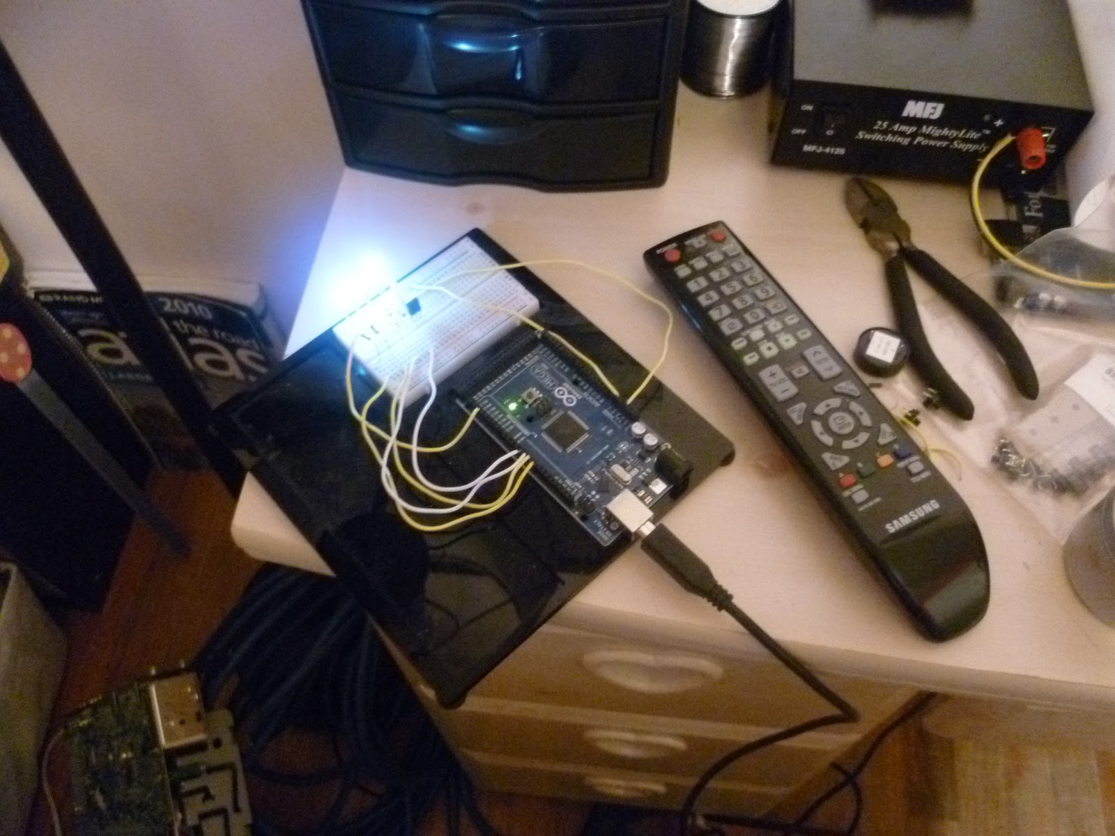
This is a good example of hacking devices with Arduino. [sspence65] has put on oa good tutorial to start from something easy and simple: IR hack.
Capturing codes from any tv remote, and using them to control devices attached to Arduino Outputs. Press a button on a TV Remote, and the code appears in the serial monitor, Add that code to the case/switch statements in the sketch to control an output pin.
On the [website] there is the full explanation and code to build the same experience, but nothing prevent you to implement a custom way for your IR devices.
Recently a new method of interacting with an ethernet-enabled Arduino board and the Internet was brought to my attention – a new system called Teleduino. In this article we test a few of the basic features and see what is possible. Please note that these are my own experiments and that Teleduino is a work in progress. So follow along and see for yourself.
Getting Started
You will need an Arduino Uno (or compatible) board and Ethernet shield with the Wiznet chip – or a Freetronics EtherTen (a much neater solution). At this stage Teleduino doesn’t support other boards such as the Mega.
Download and install the Teleduino Arduino library. This is available from the resources section of the home page. You will also need to be running Arduino IDE v1.0 or greater.
Request an API key. This identified your particular Arduino from the rest.
Get together some basic electronics components for testing, such as some LEDs and 560R resistors; sources of analog input such as an LDR or TMP36 temperature sensor; and a solderless breadboard.
Don’t forget the ethernet cable from your Arduino stack to the router!
Finally, some rudimentary knowledge about networking will be useful. (IP address, DHCP, etc.)
The Teleduino system uses pin D8 for a status LED, so you may find connecting one up now useful while experimenting. Connect as such:
Controlling digital outputs
In this example we control an LED, turning it on and off. For demonstration purposes, connect another LED with a resistor to D6 in the same method as shown above. Next, you need to upload a sketch to the Arduino. It is the
TeleduinoEthernetClientProxy.ino
which is included with the library examples. Before uploading, you need to make some modifications. The first of these is to add your API key. Go back to the email you received from Teleduino, and click on the link provided. It will take you to a website that shows a byte array variable named byte key[]. You will copy this into the sketch, replacing the same array full of hexadecimal zeros in the sketch – as shown below – with your own:
… and change one of the hexadecimal numbers to 0×00… just in case there is a clash with other addresses on your network. You never know. Finally – depending on your network router, you may need to manually allocate the IP address for your Ethernet shield and/or set the DNS server to use. To do this, scroll down to
// User configurable variables
where you can change the useDHCP and/or useDNS variables to false, and update those values below. However if you’re not sure, just leave them be unless you need to change them. Finally – upload the sketch to your Arduino, get the hardware together and plug it into the network.
Watch your status LED – it will blink a number of times, depending on the status of things. The blink levels are:
1 blink – initialising
2 blinks – starting network connection
3 blinks – connecting to the Teleduino server
4 blinks – authentication successful
5 blinks – session already exists for supplied key (sometimes happens after a quick restart – will work on next auto-restart)
6 blinks – Invalid or unauthorised key – check your API key is correctly entered in the sketch as described earlier
10 blinks – connection dropped
If all is well, after a minute yours should be on blink level 4, then it will idle back to blink level 1. Now to test the connection with our first command.
You send commands to the Arduino using a set of URLs that will contain various parameters. You will need your API key again for these URLs which is then inserted into the URL. The first will report the version of software on the Arduino. Send
however replace 999999 with your API key (and in all examples shown here). If successful, you should see something similar to the following in the web browser:
However if something is wrong, or there are connection difficulties you will see something like:
Before using digital outputs, and after every reset of the Arduino) you need to set the pin mode for the digital output to control. In our example, we use:
Note that the pin number and mode are set with single digits, as you can see above this is for pin 6, and we use mode=1 for output. You should save this as a bookmark to make life easer later on. When the command has been successfully sent, a message will be shown in the webpage, for example:
Moving forward – you turn the digital output on with the following:
and to turn it off, set the final part of the URL to
output=0
Easy. How did you go? It really is amazing to see it work. Now you can control your Arduino from almost anywhere in the world. Again, saving these as bookmarks to make things easier, or a URL shortening service.
At this point you should now have the gist of the Teleduino service and how it is operated.
There is so much more you can do, and currently the list includes (From the author):
Reset, ping, get version, get uptime, get free memory.
Define pin modes, set digital outputs, set analog outputs, read digital inputs, read analog inputs, or read all inputs with a single API call.
Define up to 2 ‘banks’ of shift registers. Each ‘bank’ can contain up to 32 cascaded shift registers, giving a total of 512 digital outputs.
Shift register outputs can be set, or merged, and expire times can be set on merges (you could set an output(s) high for X number of milliseconds).
Define, and read and write from serial port.
Read and write from EEPROM.
Define and position up to 6 servos.
Set preset values for the above functions, which get set during boot. Preset values are stored in the first 160ish bytes of the EEPROM.
For more information check the Teleduino web site, and further tutorials can be found here. Here is a simple example of Teleduino at work – controlling a light switch:
Conclusion
At this moment Teleduino is simple, works and makes a lot of ideas possible. We look forward to making more use of it in future projects, and hope you can as well. Kudos to Nathan Kennedy, and we look forward to seeing Teleduino advance and develop over the future. If all this Arduino is new to you, check out the tutorials. Thanks to Freetronics for the use of their Ethernet-enabled hardware.
In the meanwhile have fun and keep checking into tronixstuff.com. Why not follow things on twitter, Google+, subscribe for email updates or RSS using the links on the right-hand column? And join our friendly Google Group – dedicated to the projects and related items on this website. Sign up – it’s free, helpful to each other – and we can all learn something.
Planet Arduino is, or at the moment is wishing to become, an aggregation of public weblogs from around the world written by people who develop, play, think on Arduino platform and his son. The opinions expressed in those weblogs and hence this aggregation are those of the original authors. Entries on this page are owned by their authors. We do not edit, endorse or vouch for the contents of individual posts. For more information about Arduino please visit www.arduino.cc
You are currently browsing the archives for the control category.