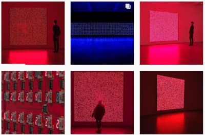
This seven segment art display makes use of a 81 seven segment red common cathode LED displays. The LEDs are arranged onto 100x100mm boards that each contain an Arduino Nano and 9 seven segment displays, daisy chained through three-pin headers located on the sides of the boards. The pins (power, ground, and serial) provide the signals necessary for propagating a program across each of the connected boards.
The first board – with two Arduino Nanos – sends instructions for which digits to light and drives the display, sending the instructions over to the next board on the chain.
In a multiplexed arrangement, a single Arduino Nano is able to drive up to 12 seven segment displays, but only 9 needed to be driven for the program, keeping D13’s built in LED and the serial pins free. Since no resistors are featured on the boards, current limiting is done through software. This was inspired by the Bubble LED displays on the Sinclair Scientific Calculator, and was done in order to achieve a greater brightness by controlling the current through the duty cycle.
The time between digits lighting up is 2ms, giving them some time to cool down. The animations in the demos featured falling and incrementing digits, as well as a random number generator using a linear feedback shift register.
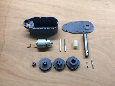
This servo/gear reduction was assembled with almost all 3D-printed parts. Apart from a brushed 36 V DC-motor, a stainless steel shaft, and screws for holding the servo together, the only other non-printed part is the BTS7960B motor driver.
Some interesting stats about the plastic servo – its stall torque is about 55 kg/cm, reaching a peak current draw of 18 A when using a 6s LiPo battery outputting 22-24 V. The shaft rotates using two 20 mm holes and lubrication. (Ball bearings were originally in the design, but they didn’t arrive on time for the assembly.)
The holes of the gears are 6.2 mm in diameter in order to fit around the shaft, although some care is taken to sand or fill the opening depending on the quality of the 3D print.
This isn’t [Brian Brocken]’s only attempt at 3D-printing gears. He’s also built severalcrawling robots, a turntable, and a wind up car made entirely from acrylic. The .stl files for the project are all available online for anyone looking to make their own 3D-printed servo gears.
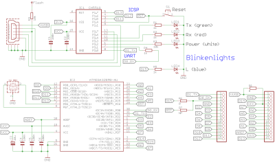
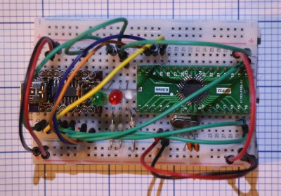
While we certainly do love the Arduino Nano for its low-cost and versatility in projects, it’s unarguable that every tools has its gripes. For one maker in particular, there were enough complaints to merit a redesign of the entire board. While Arduino may or may not be interested in incorporating these changes into a redesign of the development board, there is certainly room for a new manufacturer to step in and improve some features.
[Kevin Timmerman] takes a look at lower-cost clones of the Nano made in China to highlight a few interesting key differences that make the clones – cheaper but still compatible with legacy systems – more attractive.
The PCB manufacturing for the Arduino Nano currently places components on both sides of the board, requiring two operations for solder paste, pick-and-place, and reflow. Naturally this increases costs, simply designing a two-layer PCB with components on top lowers the price of manufacturing.
Since the ATmega328PB was released, it has proven to be a better and cheaper MCU for manufacturing than the ATmega328P, the current MCU used by the Arduino Nano and clones. While the newer MCU is not backwards compatible like its predecessor, it has additional UART, GPIO, counters, and other features that allow users to take advantage of new libraries and peripherals.
Rather than featuring the typical voltage regulator used by Arduino boards (used to allow the board to be powered by a voltage source greater than 5V), a switching regulator allows for less energy loss but a higher component cost. A better solution than both of these would be to simply not have a voltage regulator. While this may be controversial, there are sufficient battery power sources for this design to work (4 cells of AA or AAA NiMh batteries or a mobile phone charger).
The Arduino Nano uses a bootloader for handling programming the MCU, which requires the USB to serial bridge to be disconnected from anything that could interfere with the programming. Thus, programs using the COM port on the computer must release the port, including the serial monitor. Rather than using the bootloader, ICSP (in-circuit serial programming) and DebugWire are possible alternatives that connect the ICSP pins to the CH551 development board or programming via the reset pin.
There are a number of other spec and firmware improvements suggested in the writeup, as well as comparison between the Arduino Nano, Arduino Every, and Chinese clones. It’s definitely worth a look!
Fans of D&D are surely aware of the significance of a good pair of dice. What if your dice were not only stylish, but smart? For anyone who’s ever had to deal with playing board games with less than reputable siblings or friends, the electric die just might be your savior.
The dice are configured via Bluetooth, tracking rolls and stats over the course of gameplay captured by an accelerometer.
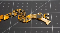
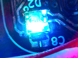
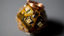
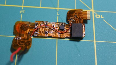
The PCB had to have a flexible surface – specifically in the shape of an unfolded icosahedron – in order to form the shape of the die which constrains the design to two layers. Each face contains an LED facing outwards to light up the number on that side. The LEDs are directly powered by a rechargeable battery, which uses a small coil for wireless inductive charging. Rather than opting for a Qi charger chipset, which regulates the maximum amount of power transmitted if the efficiency falls below a threshold, [Jean Simonet] uses a simpler charger setup using a full bridge rectifier, capacitors, and a linear regulator to create a stable 5V supply for the receiving end.
While the initial design for the die required an injection molded plastic shell, an easier solution was to simply cast the designs in resin. The electronics are placed into a dice mold and cast just as a regular die would be.
This luckily also solved the issue of needing to fit the components inside a screw-on container with a removable lid, which presented a hassle in terms of finding a battery that would fit the dimensions. The LEDs – purchased for cheap on Alibaba – are daisy chained to reduce the complexity of the routing.
One issue with the LEDs, however, is that the internal PWMs modulating the intensity remain on even at an intensity of 0, constantly drawing 21 mA (for the 21 LEDs on the die). This causes the battery to die after 2-3 hours. The solution [Simonet] used was to add a transistor to cut off power to the LEDs and to have the MCU toggle the transistor when the LEDs are turned off. Even this solution didn’t solve the entire problem since the LEDs still drain current from the data and clock lines, so those lines had to be low before going to sleep.
There were some stability issues with using a small buck converter to bring the LiPo voltage down to 3.3V, so the power regulation was done directly by the MCU instead. Switching the die off is controlled by a magnetic switch connected to a power buck converter that turns off logic when a magnet is present. This initially caused the LED control lines to become floating when power was turned off, turning the LEDs to arbitrary colors. The solution was to wire the output of the magnetic sensor to the MCU and to allow the software to handle the LEDs as well.
Maybe it’s because creator [Simonet] happens to be a game developer as well, but the early development stages of the electronic die (CAD, circuit schematics, prototyping, hand soldering components) were streamed on Twitch, adding some interactivity to even the build phase. The end result may be small, but these dice certainly have large brains!
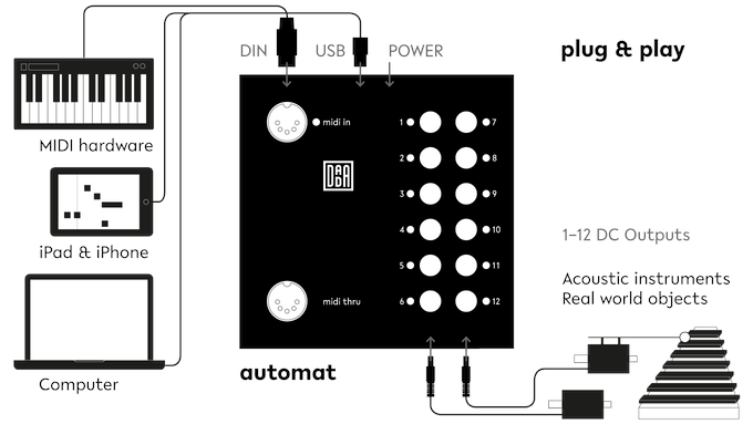
Fans of MaKey MaKey may find this project similar, but there’s a lot more to the Mini Automat than making music from fruit.
The idea for the Mini Automat (which is an off-shoot of the original Automat project by [Dada Machines]) is to make music accessible to anyone. The device functions as a plug and play MIDI-controller that connects to a computer, MIDI workstation (keyboards and sequencers), or DAW for input and triggers actuators on the output to create music.
The modifications make the originally Automat more hackable by making the board compatible with Arduino and Circuit Python, as well as adding in digital and analog pins for connecting to sensors, buttons, or light systems.
The team has released all schematics, firmware, and software, with only the board layouts unreleased to the public. From solenoids that push, pull, jiggle, smash, and bash at drums to surfaces that vibrate screws and beads, there’s a huge variety of household objects that can be used to make complex layered musical compositions, even for a one-person musician.
The Berlin-based team works on open source music tech hardware with the hopes of bringing environmentally and financially sustainable ideas to market.
For anyone who’s ever had to make their own tea, steeping it for the right amount of time can be a pain. That’s precisely the problem that the automatic tea brewing robot solves with its painless approach to brewing tea, built by Slovenian electrical engineering student [Kristjan Berce].
You can use the robot by setting a timer on the knob, at which point the robot raises it arm for the tea bag then dips in the water every 30 seconds until the time has passed. At the end of the timer, the bag is raised clear of the cup to end the brewing. It’s a remarkably simple design that almost evokes chindogu (the Japanese art of useless inventions) if not for the fact that the robot actually serves a useful purpose.
The components for 3D printing the robot are available online, consisting of a case, a container for the Arduino-powered electronics, the lever for holding the tea, and the gear that raises the lever up and down. The device also uses an integrated Li-Ion battery with an accessible charging port and integrated BMS. A 35BYJ46 stepper motor and ULN2003 driver are used to move the 3D printed mechanism. The device uses a potentiometer for setting the steeping time between 1 and 9 minutes, and there’s even a buzzer for indicating once the tea is done brewing.
Our five rounds of Hackaday Prize 2018 challenges have just wrapped up, and we’re looking forward to see where the chips fall in the final ranking. While we’re waiting for the winners to be announced at Hackaday Superconference, it’s fun to take a look back at one of our past winners. Watch [Reinier van der Lee] give the latest updates on his Vinduino project (video also embedded after the break) to a Hackaday Los Angeles meetup earlier this year.
Vinduino started with [Reinier]’s desire to better understand what happens to irrigation water under the surface, measuring soil moisture at different depths. This knowledge informs more efficient use of irrigation water, as we’ve previously covered in more detail. What [Reinier] has been focused on is improving usability of the system by networking the sensors wirelessly versus having to walk up and physically attach a reader unit.
His thought started the same as ours – put them on WiFi! But adding WiFi coverage across his entire vineyard was not going to be cost-effective. After experimenting with various communication schemes, he has settled on LoRa. Designed to trade raw bandwidth for long range with low power requirements, it is a perfect match for a network of soil moisture sensors.
In the video [Reinier] gives an overview of LoRa for those who might be unfamiliar. Followed by results of his experiments integrating LoRa functionality into Vinduino, and ending with a call to action for hackers to help grow the LoRa network. It sounds like he’s become quite the champion for the cause! He’s even giving a hands-on workshop at Supercon where you can build your own LoRa connected sensor. (Get tickets here.)
We’re always happy to see open-source hardware projects like Vinduino succeed, transitioning to a product that solve real world problems. We know there are even more promising ideas out there, which is why Hackaday’s sister company Tindie is funding a Project to Product program to help this year’s winners follow in Vinduino’s footsteps. We look forward to sharing more success stories yet to come.
While most of us take being able to remotely control a television or other appliance for granted, for the millions of people with some form of disability, this can present a challenge. In order to help those with limited mobility, Cassio Batista along with Erick Campos have come up with a system that translates head movements into infrared (IR) control signals.
In the project’s video seen below, Batista shows off how he can move his head to turn a TV on and off, as well as control channel selection and volume. A webcam captures these gestures, which are passed on to a Linux-based C.H.I.P. board that translates the movements using OpenCV. Finally, an Arduino Uno receives these commands over Bluetooth and signals the TV as needed via IR.
In addition to television, this system could easily be applied to other IR-based appliances, making lives easier, or perhaps simply eliminating a physical remote altogether.
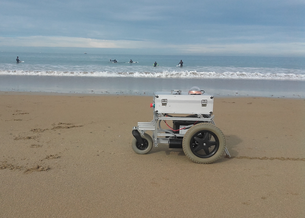
For this year’s Hackaday Prize, hacker “Ulysse” has designed an autonomous beach art rover using an Arduino Mega and a pair of Micros.
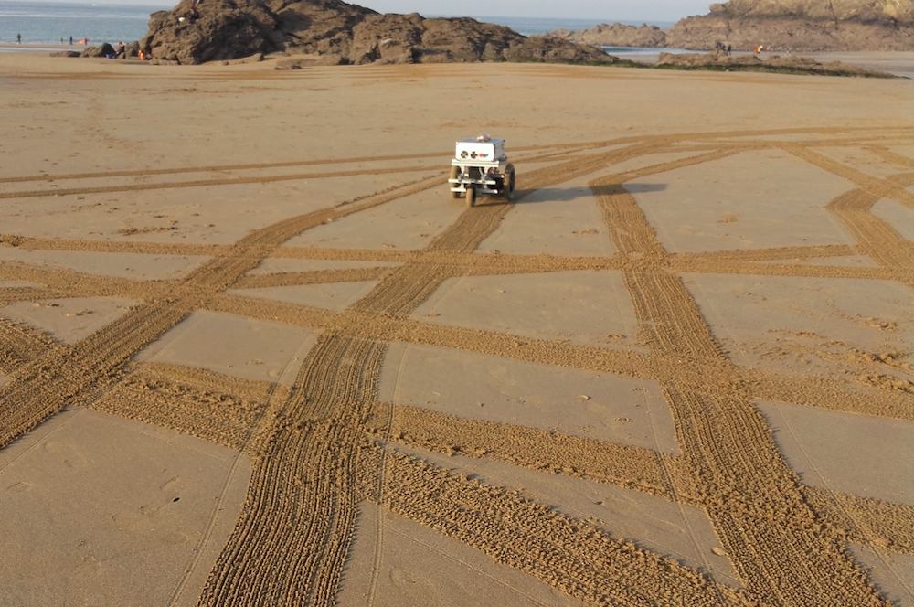
While walking along the shore, the footprints you leave behind are mildly interesting, and perhaps you might go to the effort of scraping a pattern in the sand if you were feeling rather creative. If, however, you wanted to make drawings on a massive scale, Ulysse’s robot “Pablo Odysseus” looks like an elegant solution.
The Arduino-powered rover uses two wheelchair motors to propel it along the beach, as well as a rake to leave a mark as to where it’s been. Navigation is provided by a GNSS receiver (a more general term for “GPS”), a digital compass, and an odometer set up on each of the motors. Meanwhile, USB dongles enable it to communicate wirelessly with a smartphone and laptop.
Now, Ulysse can simply program in an artistic pattern, and Pablo will take care of the rest! You can see more about this project on Hackaday.io and GitHub.
Planet Arduino is, or at the moment is wishing to become, an aggregation of public weblogs from around the world written by people who develop, play, think on Arduino platform and his son. The opinions expressed in those weblogs and hence this aggregation are those of the original authors. Entries on this page are owned by their authors. We do not edit, endorse or vouch for the contents of individual posts. For more information about Arduino please visit www.arduino.cc
You are currently browsing the archives for the Hackaday Prize category.