Posts | Comments

Planet Arduino

Archive for the ‘compatible’ Category

Use the Maxim MAX7219 LED display driver with Arduino in Chapter 56 of our Arduino Tutorials. The first chapter is here, the complete series is detailed here.

Introduction

Sooner or later Arduino enthusiasts and beginners alike will come across the MAX7219 IC. And for good reason, it’s a simple and somewhat inexpensive method of controlling 64 LEDs in either matrix or numeric display form. Furthermore they can be chained together to control two or more units for even more LEDs. Overall – they’re a lot of fun and can also be quite useful, so let’s get started.

Here’s an example of a MAX7219 and another IC which is a functional equivalent, the AS1107 from Austria Microsystems. You might not see the AS1107 around much, but it can be cheaper – so don’t be afraid to use that instead:

MAX7219 AS1107

When shopping for MAX7219s you may notice the wild price fluctuations between various sellers. We’ve researched that and have a separate article for your consideration.

 At first glance you may think that it takes a lot of real estate, but it saves some as well. As mentioned earlier, the MAX7219 can completely control 64 individual LEDs – including maintaining equal brightness, and allowing you to adjust the brightness of the LEDs either with hardware or software (or both). It can refresh the LEDs at around 800 Hz, so no more flickering, uneven LED displays.

You can even switch the display off for power saving mode, and still send it data while it is off. And another good thing – when powered up, it keeps the LEDs off, so no wacky displays for the first seconds of operation. For more technical information, here is the data sheet: MAX7219.pdf. Now to put it to work for us – we’ll demonstrate using one or more 8 x 8 LED matrix displays, as well as 8 digits of 7-segment LED numbers.

Before continuing, download and install the LedControl Arduino library as it is essential for using the MAX7219.

Controlling LED matrix displays with the MAX7219

First of all, let’s examine the hardware side of things. Here is the pinout diagram for the MAX7219:

MAX7219 pinout

The MAX7219 drives eight LEDs at a time, and by rapidly switching banks of eight your eyes don’t see the changes. Wiring up a matrix is very simple – if you have a common matrix with the following schematic:

LED matrix pinoutsconnect the MAX7219 pins labelled DP, A~F to the row pins respectively, and the MAX7219 pins labelled DIG0~7 to the column pins respectively. A total example circuit with the above matrix  is as follows:

MAX7219 example LED matrix circuit

The circuit is quite straight forward, except we have a resistor between 5V and MAX7219 pin 18. The MAX7219 is a constant-current LED driver, and the value of the resistor is used to set the current flow to the LEDs. Have a look at table eleven on page eleven of the data sheet:

MAX7219 resistor tableYou’ll need to know the voltage and forward current for your LED matrix or numeric display, then match the value on the table. E.g. if you have a 2V 20 mA LED, your resistor value will be 28kΩ (the values are in kΩ). Finally, the MAX7219 serial in, load and clock pins will go to Arduino digital pins which are specified in the sketch. We’ll get to that in the moment, but before that let’s return to the matrix modules.

In the last few months there has been a proliferation of inexpensive kits that contain a MAX7219 or equivalent, and an LED matrix. These are great for experimenting with and can save you a lot of work – some examples of which are shown below:

MAX7219 LED matrix modules

At the top is an example from ebay, and the pair on the bottom are the units from a recent kit review. We’ll use these for our demonstrations as well.

Now for the sketch. You need the following two lines at the beginning of the sketch:

#include "LedControl.h" 
LedControl lc=LedControl(12,11,10,1);

The first pulls in the library, and the second line sets up an instance to control. The four parameters are as follows:

  1. the digital pin connected to pin 1 of the MAX7219 (“data in”)
  2. the digital pin connected to pin 13 of the MAX7219 (“CLK or clock”)
  3. the digital pin connected to pin 12 of the MAX7219 (“LOAD”)
  4. The number of MAX7219s connected.

If you have more than one MAX7219, connect the DOUT (“data out”) pin of the first MAX7219 to pin 1 of the second, and so on. However the CLK and LOAD pins are all connected in parallel and then back to the Arduino.

Next, two more vital functions that you’d normally put in void setup():

lc.shutdown(0,false);
lc.setIntensity(0,8);

The first line above turns the LEDs connected to the MAX7219 on. If you set TRUE, you can send data to the MAX7219 but the LEDs will stay off. The second line adjusts the brightness of the LEDs in sixteen stages. For both of those functions (and all others from the LedControl) the first parameter is the number of the MAX7219 connected. If you have one, the parameter is zero… for two MAX7219s, it’s 1 and so on.

Finally, to turn an individual LED in the matrix on or off, use:

lc.setLed(0,col,row,true);

which turns on an LED positioned at col, row connected to MAX7219 #1. Change TRUE to FALSE to turn it off. These functions are demonstrated in the following sketch:

#include "LedControl.h" //  need the library
LedControl lc=LedControl(12,11,10,1); // 

// pin 12 is connected to the MAX7219 pin 1
// pin 11 is connected to the CLK pin 13
// pin 10 is connected to LOAD pin 12
// 1 as we are only using 1 MAX7219

void setup()
{
  // the zero refers to the MAX7219 number, it is zero for 1 chip
  lc.shutdown(0,false);// turn off power saving, enables display
  lc.setIntensity(0,8);// sets brightness (0~15 possible values)
  lc.clearDisplay(0);// clear screen
}
void loop()
{
  for (int row=0; row<8; row++)
  {
    for (int col=0; col<8; col++)
    {
      lc.setLed(0,col,row,true); // turns on LED at col, row
      delay(25);
    }
  }

  for (int row=0; row<8; row++)
  {
    for (int col=0; col<8; col++)
    {
      lc.setLed(0,col,row,false); // turns off LED at col, row
      delay(25);
    }
  }
}

And a quick video of the results:

How about controlling two MAX7219s? Or more? The hardware modifications are easy – connect the serial data out pin from your first MAX7219 to the data in pin on the second (and so on), and the LOAD and CLOCK pins from the first MAX7219 connect to the second (and so on). You will of course still need the 5V, GND, resistor, capacitors etc. for the second and subsequent MAX7219.

You will also need to make a few changes in your sketch. The first is to tell it how many MAX7219s you’re using in the following line:

LedControl lc=LedControl(12,11,10,X);

by replacing X with the quantity. Then whenever you’re using  a MAX7219 function, replace the (previously used) zero with the number of the MAX7219 you wish to address. They are numbered from zero upwards, with the MAX7219 directly connected to the Arduino as unit zero, then one etc. To demonstrate this, we replicate the previous example but with two MAX7219s:

#include "LedControl.h" //  need the library
LedControl lc=LedControl(12,11,10,2); // 

// pin 12 is connected to the MAX7219 pin 1
// pin 11 is connected to the CLK pin 13
// pin 10 is connected to LOAD pin 12
// 1 as we are only using 1 MAX7219

void setup()
{
  lc.shutdown(0,false);// turn off power saving, enables display
  lc.setIntensity(0,8);// sets brightness (0~15 possible values)
  lc.clearDisplay(0);// clear screen

  lc.shutdown(1,false);// turn off power saving, enables display
  lc.setIntensity(1,8);// sets brightness (0~15 possible values)
  lc.clearDisplay(1);// clear screen
}

void loop()
{
  for (int row=0; row<8; row++)
  {
    for (int col=0; col<8; col++)
    {
      lc.setLed(0,col,row,true); // turns on LED at col, row
      lc.setLed(1,col,row,false); // turns on LED at col, row
      delay(25);
    }
  }

  for (int row=0; row<8; row++)
  {
    for (int col=0; col<8; col++)
    {
      lc.setLed(0,col,row,false); // turns off LED at col, row
      lc.setLed(1,col,row,true); // turns on LED at col, row      
      delay(25);
    }
  }
}

And again, a quick demonstration:

Another fun use of the MAX7219 and LED matrices is to display scrolling text. For the case of simplicity we’ll use the LedControl library and the two LED matrix modules from the previous examples.

First our example sketch – it is quite long however most of this is due to defining the characters for each letter of the alphabet and so on. We’ll explain it at the other end!

// based on an orginal sketch by Arduino forum member "danigom"
// http://forum.arduino.cc/index.php?action=profile;u=188950

#include <avr/pgmspace.h>
#include <LedControl.h>

const int numDevices = 2;      // number of MAX7219s used
const long scrollDelay = 75;   // adjust scrolling speed

unsigned long bufferLong [14] = {0}; 

LedControl lc=LedControl(12,11,10,numDevices);

prog_uchar scrollText[] PROGMEM ={
    "  THE QUICK BROWN FOX JUMPED OVER THE LAZY DOG 1234567890 the quick brown fox jumped over the lazy dog   \0"};

void setup(){
    for (int x=0; x<numDevices; x++){
        lc.shutdown(x,false);       //The MAX72XX is in power-saving mode on startup
        lc.setIntensity(x,8);       // Set the brightness to default value
        lc.clearDisplay(x);         // and clear the display
    }
}

void loop(){ 
    scrollMessage(scrollText);
    scrollFont();
}

///////////////////////////////////////////////////////////////////////////////////////////////////////////////////

prog_uchar font5x7 [] PROGMEM = {      //Numeric Font Matrix (Arranged as 7x font data + 1x kerning data)
    B00000000,	//Space (Char 0x20)
    B00000000,
    B00000000,
    B00000000,
    B00000000,
    B00000000,
    B00000000,
    6,

    B10000000,	//!
    B10000000,
    B10000000,
    B10000000,
    B00000000,
    B00000000,
    B10000000,
    2,

    B10100000,	//"
    B10100000,
    B10100000,
    B00000000,
    B00000000,
    B00000000,
    B00000000,
    4,

    B01010000,	//#
    B01010000,
    B11111000,
    B01010000,
    B11111000,
    B01010000,
    B01010000,
    6,

    B00100000,	//$
    B01111000,
    B10100000,
    B01110000,
    B00101000,
    B11110000,
    B00100000,
    6,

    B11000000,	//%
    B11001000,
    B00010000,
    B00100000,
    B01000000,
    B10011000,
    B00011000,
    6,

    B01100000,	//&
    B10010000,
    B10100000,
    B01000000,
    B10101000,
    B10010000,
    B01101000,
    6,

    B11000000,	//'
    B01000000,
    B10000000,
    B00000000,
    B00000000,
    B00000000,
    B00000000,
    3,

    B00100000,	//(
    B01000000,
    B10000000,
    B10000000,
    B10000000,
    B01000000,
    B00100000,
    4,

    B10000000,	//)
    B01000000,
    B00100000,
    B00100000,
    B00100000,
    B01000000,
    B10000000,
    4,

    B00000000,	//*
    B00100000,
    B10101000,
    B01110000,
    B10101000,
    B00100000,
    B00000000,
    6,

    B00000000,	//+
    B00100000,
    B00100000,
    B11111000,
    B00100000,
    B00100000,
    B00000000,
    6,

    B00000000,	//,
    B00000000,
    B00000000,
    B00000000,
    B11000000,
    B01000000,
    B10000000,
    3,

    B00000000,	//-
    B00000000,
    B11111000,
    B00000000,
    B00000000,
    B00000000,
    B00000000,
    6,

    B00000000,	//.
    B00000000,
    B00000000,
    B00000000,
    B00000000,
    B11000000,
    B11000000,
    3,

    B00000000,	///
    B00001000,
    B00010000,
    B00100000,
    B01000000,
    B10000000,
    B00000000,
    6,

    B01110000,	//0
    B10001000,
    B10011000,
    B10101000,
    B11001000,
    B10001000,
    B01110000,
    6,

    B01000000,	//1
    B11000000,
    B01000000,
    B01000000,
    B01000000,
    B01000000,
    B11100000,
    4,

    B01110000,	//2
    B10001000,
    B00001000,
    B00010000,
    B00100000,
    B01000000,
    B11111000,
    6,

    B11111000,	//3
    B00010000,
    B00100000,
    B00010000,
    B00001000,
    B10001000,
    B01110000,
    6,

    B00010000,	//4
    B00110000,
    B01010000,
    B10010000,
    B11111000,
    B00010000,
    B00010000,
    6,

    B11111000,	//5
    B10000000,
    B11110000,
    B00001000,
    B00001000,
    B10001000,
    B01110000,
    6,

    B00110000,	//6
    B01000000,
    B10000000,
    B11110000,
    B10001000,
    B10001000,
    B01110000,
    6,

    B11111000,	//7
    B10001000,
    B00001000,
    B00010000,
    B00100000,
    B00100000,
    B00100000,
    6,

    B01110000,	//8
    B10001000,
    B10001000,
    B01110000,
    B10001000,
    B10001000,
    B01110000,
    6,

    B01110000,	//9
    B10001000,
    B10001000,
    B01111000,
    B00001000,
    B00010000,
    B01100000,
    6,

    B00000000,	//:
    B11000000,
    B11000000,
    B00000000,
    B11000000,
    B11000000,
    B00000000,
    3,

    B00000000,	//;
    B11000000,
    B11000000,
    B00000000,
    B11000000,
    B01000000,
    B10000000,
    3,

    B00010000,	//<
    B00100000,
    B01000000,
    B10000000,
    B01000000,
    B00100000,
    B00010000,
    5,

    B00000000,	//=
    B00000000,
    B11111000,
    B00000000,
    B11111000,
    B00000000,
    B00000000,
    6,

    B10000000,	//>
    B01000000,
    B00100000,
    B00010000,
    B00100000,
    B01000000,
    B10000000,
    5,

    B01110000,	//?
    B10001000,
    B00001000,
    B00010000,
    B00100000,
    B00000000,
    B00100000,
    6,

    B01110000,	//@
    B10001000,
    B00001000,
    B01101000,
    B10101000,
    B10101000,
    B01110000,
    6,

    B01110000,	//A
    B10001000,
    B10001000,
    B10001000,
    B11111000,
    B10001000,
    B10001000,
    6,

    B11110000,	//B
    B10001000,
    B10001000,
    B11110000,
    B10001000,
    B10001000,
    B11110000,
    6,

    B01110000,	//C
    B10001000,
    B10000000,
    B10000000,
    B10000000,
    B10001000,
    B01110000,
    6,

    B11100000,	//D
    B10010000,
    B10001000,
    B10001000,
    B10001000,
    B10010000,
    B11100000,
    6,

    B11111000,	//E
    B10000000,
    B10000000,
    B11110000,
    B10000000,
    B10000000,
    B11111000,
    6,

    B11111000,	//F
    B10000000,
    B10000000,
    B11110000,
    B10000000,
    B10000000,
    B10000000,
    6,

    B01110000,	//G
    B10001000,
    B10000000,
    B10111000,
    B10001000,
    B10001000,
    B01111000,
    6,

    B10001000,	//H
    B10001000,
    B10001000,
    B11111000,
    B10001000,
    B10001000,
    B10001000,
    6,

    B11100000,	//I
    B01000000,
    B01000000,
    B01000000,
    B01000000,
    B01000000,
    B11100000,
    4,

    B00111000,	//J
    B00010000,
    B00010000,
    B00010000,
    B00010000,
    B10010000,
    B01100000,
    6,

    B10001000,	//K
    B10010000,
    B10100000,
    B11000000,
    B10100000,
    B10010000,
    B10001000,
    6,

    B10000000,	//L
    B10000000,
    B10000000,
    B10000000,
    B10000000,
    B10000000,
    B11111000,
    6,

    B10001000,	//M
    B11011000,
    B10101000,
    B10101000,
    B10001000,
    B10001000,
    B10001000,
    6,

    B10001000,	//N
    B10001000,
    B11001000,
    B10101000,
    B10011000,
    B10001000,
    B10001000,
    6,

    B01110000,	//O
    B10001000,
    B10001000,
    B10001000,
    B10001000,
    B10001000,
    B01110000,
    6,

    B11110000,	//P
    B10001000,
    B10001000,
    B11110000,
    B10000000,
    B10000000,
    B10000000,
    6,

    B01110000,	//Q
    B10001000,
    B10001000,
    B10001000,
    B10101000,
    B10010000,
    B01101000,
    6,

    B11110000,	//R
    B10001000,
    B10001000,
    B11110000,
    B10100000,
    B10010000,
    B10001000,
    6,

    B01111000,	//S
    B10000000,
    B10000000,
    B01110000,
    B00001000,
    B00001000,
    B11110000,
    6,

    B11111000,	//T
    B00100000,
    B00100000,
    B00100000,
    B00100000,
    B00100000,
    B00100000,
    6,

    B10001000,	//U
    B10001000,
    B10001000,
    B10001000,
    B10001000,
    B10001000,
    B01110000,
    6,

    B10001000,	//V
    B10001000,
    B10001000,
    B10001000,
    B10001000,
    B01010000,
    B00100000,
    6,

    B10001000,	//W
    B10001000,
    B10001000,
    B10101000,
    B10101000,
    B10101000,
    B01010000,
    6,

    B10001000,	//X
    B10001000,
    B01010000,
    B00100000,
    B01010000,
    B10001000,
    B10001000,
    6,

    B10001000,	//Y
    B10001000,
    B10001000,
    B01010000,
    B00100000,
    B00100000,
    B00100000,
    6,

    B11111000,	//Z
    B00001000,
    B00010000,
    B00100000,
    B01000000,
    B10000000,
    B11111000,
    6,

    B11100000,	//[
    B10000000,
    B10000000,
    B10000000,
    B10000000,
    B10000000,
    B11100000,
    4,

    B00000000,	//(Backward Slash)
    B10000000,
    B01000000,
    B00100000,
    B00010000,
    B00001000,
    B00000000,
    6,

    B11100000,	//]
    B00100000,
    B00100000,
    B00100000,
    B00100000,
    B00100000,
    B11100000,
    4,

    B00100000,	//^
    B01010000,
    B10001000,
    B00000000,
    B00000000,
    B00000000,
    B00000000,
    6,

    B00000000,	//_
    B00000000,
    B00000000,
    B00000000,
    B00000000,
    B00000000,
    B11111000,
    6,

    B10000000,	//`
    B01000000,
    B00100000,
    B00000000,
    B00000000,
    B00000000,
    B00000000,
    4,

    B00000000,	//a
    B00000000,
    B01110000,
    B00001000,
    B01111000,
    B10001000,
    B01111000,
    6,

    B10000000,	//b
    B10000000,
    B10110000,
    B11001000,
    B10001000,
    B10001000,
    B11110000,
    6,

    B00000000,	//c
    B00000000,
    B01110000,
    B10001000,
    B10000000,
    B10001000,
    B01110000,
    6,

    B00001000,	//d
    B00001000,
    B01101000,
    B10011000,
    B10001000,
    B10001000,
    B01111000,
    6,

    B00000000,	//e
    B00000000,
    B01110000,
    B10001000,
    B11111000,
    B10000000,
    B01110000,
    6,

    B00110000,	//f
    B01001000,
    B01000000,
    B11100000,
    B01000000,
    B01000000,
    B01000000,
    6,

    B00000000,	//g
    B01111000,
    B10001000,
    B10001000,
    B01111000,
    B00001000,
    B01110000,
    6,

    B10000000,	//h
    B10000000,
    B10110000,
    B11001000,
    B10001000,
    B10001000,
    B10001000,
    6,

    B01000000,	//i
    B00000000,
    B11000000,
    B01000000,
    B01000000,
    B01000000,
    B11100000,
    4,

    B00010000,	//j
    B00000000,
    B00110000,
    B00010000,
    B00010000,
    B10010000,
    B01100000,
    5,

    B10000000,	//k
    B10000000,
    B10010000,
    B10100000,
    B11000000,
    B10100000,
    B10010000,
    5,

    B11000000,	//l
    B01000000,
    B01000000,
    B01000000,
    B01000000,
    B01000000,
    B11100000,
    4,

    B00000000,	//m
    B00000000,
    B11010000,
    B10101000,
    B10101000,
    B10001000,
    B10001000,
    6,

    B00000000,	//n
    B00000000,
    B10110000,
    B11001000,
    B10001000,
    B10001000,
    B10001000,
    6,

    B00000000,	//o
    B00000000,
    B01110000,
    B10001000,
    B10001000,
    B10001000,
    B01110000,
    6,

    B00000000,	//p
    B00000000,
    B11110000,
    B10001000,
    B11110000,
    B10000000,
    B10000000,
    6,

    B00000000,	//q
    B00000000,
    B01101000,
    B10011000,
    B01111000,
    B00001000,
    B00001000,
    6,

    B00000000,	//r
    B00000000,
    B10110000,
    B11001000,
    B10000000,
    B10000000,
    B10000000,
    6,

    B00000000,	//s
    B00000000,
    B01110000,
    B10000000,
    B01110000,
    B00001000,
    B11110000,
    6,

    B01000000,	//t
    B01000000,
    B11100000,
    B01000000,
    B01000000,
    B01001000,
    B00110000,
    6,

    B00000000,	//u
    B00000000,
    B10001000,
    B10001000,
    B10001000,
    B10011000,
    B01101000,
    6,

    B00000000,	//v
    B00000000,
    B10001000,
    B10001000,
    B10001000,
    B01010000,
    B00100000,
    6,

    B00000000,	//w
    B00000000,
    B10001000,
    B10101000,
    B10101000,
    B10101000,
    B01010000,
    6,

    B00000000,	//x
    B00000000,
    B10001000,
    B01010000,
    B00100000,
    B01010000,
    B10001000,
    6,

    B00000000,	//y
    B00000000,
    B10001000,
    B10001000,
    B01111000,
    B00001000,
    B01110000,
    6,

    B00000000,	//z
    B00000000,
    B11111000,
    B00010000,
    B00100000,
    B01000000,
    B11111000,
    6,

    B00100000,	//{
    B01000000,
    B01000000,
    B10000000,
    B01000000,
    B01000000,
    B00100000,
    4,

    B10000000,	//|
    B10000000,
    B10000000,
    B10000000,
    B10000000,
    B10000000,
    B10000000,
    2,

    B10000000,	//}
    B01000000,
    B01000000,
    B00100000,
    B01000000,
    B01000000,
    B10000000,
    4,

    B00000000,	//~
    B00000000,
    B00000000,
    B01101000,
    B10010000,
    B00000000,
    B00000000,
    6,

    B01100000,	// (Char 0x7F)
    B10010000,
    B10010000,
    B01100000,
    B00000000,
    B00000000,
    B00000000,
    5
};

void scrollFont() {
    for (int counter=0x20;counter<0x80;counter++){
        loadBufferLong(counter);
        delay(500);
    }
}

// Scroll Message
void scrollMessage(prog_uchar * messageString) {
    int counter = 0;
    int myChar=0;
    do {
        // read back a char 
        myChar =  pgm_read_byte_near(messageString + counter); 
        if (myChar != 0){
            loadBufferLong(myChar);
        }
        counter++;
    } 
    while (myChar != 0);
}
// Load character into scroll buffer
void loadBufferLong(int ascii){
    if (ascii >= 0x20 && ascii <=0x7f){
        for (int a=0;a<7;a++){                      // Loop 7 times for a 5x7 font
            unsigned long c = pgm_read_byte_near(font5x7 + ((ascii - 0x20) * 8) + a);     // Index into character table to get row data
            unsigned long x = bufferLong [a*2];     // Load current scroll buffer
            x = x | c;                              // OR the new character onto end of current
            bufferLong [a*2] = x;                   // Store in buffer
        }
        byte count = pgm_read_byte_near(font5x7 +((ascii - 0x20) * 8) + 7);     // Index into character table for kerning data
        for (byte x=0; x<count;x++){
            rotateBufferLong();
            printBufferLong();
            delay(scrollDelay);
        }
    }
}
// Rotate the buffer
void rotateBufferLong(){
    for (int a=0;a<7;a++){                      // Loop 7 times for a 5x7 font
        unsigned long x = bufferLong [a*2];     // Get low buffer entry
        byte b = bitRead(x,31);                 // Copy high order bit that gets lost in rotation
        x = x<<1;                               // Rotate left one bit
        bufferLong [a*2] = x;                   // Store new low buffer
        x = bufferLong [a*2+1];                 // Get high buffer entry
        x = x<<1;                               // Rotate left one bit
        bitWrite(x,0,b);                        // Store saved bit
        bufferLong [a*2+1] = x;                 // Store new high buffer
    }
}  
// Display Buffer on LED matrix
void printBufferLong(){
  for (int a=0;a<7;a++){                    // Loop 7 times for a 5x7 font
    unsigned long x = bufferLong [a*2+1];   // Get high buffer entry
    byte y = x;                             // Mask off first character
    lc.setRow(3,a,y);                       // Send row to relevent MAX7219 chip
    x = bufferLong [a*2];                   // Get low buffer entry
    y = (x>>24);                            // Mask off second character
    lc.setRow(2,a,y);                       // Send row to relevent MAX7219 chip
    y = (x>>16);                            // Mask off third character
    lc.setRow(1,a,y);                       // Send row to relevent MAX7219 chip
    y = (x>>8);                             // Mask off forth character
    lc.setRow(0,a,y);                       // Send row to relevent MAX7219 chip
  }
}

The pertinent parts are at the top of the sketch – the following line sets the number of MAX7219s in the hardware:

const int numDevices = 2;

The following can be adjusted to change the speed of text scrolling:

const long scrollDelay = 75;

… then place the text to scroll in the following (for example):

prog_uchar scrollText[] PROGMEM ={
    "  THE QUICK BROWN FOX JUMPED OVER THE LAZY DOG 1234567890 the quick brown fox jumped over the lazy dog   \0"};

Finally – to scroll the text on demand, use the following:

scrollMessage(scrollText);

You can then incorporate the code into your own sketches. And a video of the example sketch in action:

Although we used the LedControl library, there are many others out there for scrolling text. One interesting example is Parola  – which is incredibly customisable. If you’re looking for a much larger device to scroll text, check out the Freetronics DMD range.

Controlling LED numeric displays with the MAX7219

Using the MAX7219 and the LedControl library you can also drive numeric LED displays – up to eight digits from the one MAX7219. This gives you the ability to make various numeric displays that are clear to read and easy to control. When shopping around for numeric LED displays, make sure you have the common-cathode type.

Connecting numeric displays is quite simple, consider the following schematic which should appear familiar by now:

MAX7219 7-segment schematic

The schematic shows the connections for modules or groups of up to eight digits. Each digit’s A~F and dp (decimal point) anodes connect together to the MAX7219, and each digit’s cathode connects in order as well. The MAX7219 will display each digit in turn by using one cathode at a time. Of course if you want more than eight digits, connect another MAX7219 just as we did with the LED matrices previously.

The required code in the sketch is identical to the LED matrix code, however to display individual digits we use:

lc.setDigit(A, B, C, D);

where A is the MAX7219 we’re using, B is the digit to use (from a possible 0 to 7), C is the digit to display (0~9… if you use 10~15 it will display A~F respectively) and D is false/true (digit on or off). You can also send basic characters such as a dash “-” with the following:

lc.setChar(A, B,'-',false);

Now let’s put together an example of eight digits:

#include "LedControl.h" //  need the library
LedControl lc=LedControl(12,11,10,1); // lc is our object
// pin 12 is connected to the MAX7219 pin 1
// pin 11 is connected to the CLK pin 13
// pin 10 is connected to LOAD pin 12
// 1 as we are only using 1 MAX7219
void setup()
{
  // the zero refers to the MAX7219 number, it is zero for 1 chip
  lc.shutdown(0,false);// turn off power saving, enables display
  lc.setIntensity(0,8);// sets brightness (0~15 possible values)
  lc.clearDisplay(0);// clear screen
}
void loop()
{
  for (int a=0; a<8; a++)
  {
    lc.setDigit(0,a,a,true);
    delay(100);
  }
  for (int a=0; a<8; a++)
  {
    lc.setDigit(0,a,8,1);
    delay(100);
  }
  for (int a=0; a<8; a++)
  {
    lc.setDigit(0,a,0,false);
    delay(100);
  }
  for (int a=0; a<8; a++)
  {
    lc.setChar(0,a,' ',false);
    delay(100);
  }
  for (int a=0; a<8; a++)
  {
    lc.setChar(0,a,'-',false);
    delay(100);
  }
  for (int a=0; a<8; a++)
  {
    lc.setChar(0,a,' ',false);
    delay(100);
  }
}

and the sketch in action:

Conclusion

By now you’re on your way to controlling an incredibly useful part with your Arduino. Don’t forget – there are many variations of Arduino libraries for the MAX7219, we can’t cover each one – so have fun and experiment with them. And if you enjoyed the tutorial, or want to introduce someone else to the interesting world of Arduino – check out my book (now in a third printing!) “Arduino Workshop” from No Starch Press.

In the meanwhile have fun and keep checking into tronixstuff.com. Why not follow things on twitterGoogle+, subscribe  for email updates or RSS using the links on the right-hand column? And join our friendly Google Group – dedicated to the projects and related items on this website. Sign up – it’s free, helpful to each other –  and we can all learn something.

The post Tutorial – Arduino and the MAX7219 LED Display Driver IC appeared first on tronixstuff.

Aug
28

Initial Review – Goldilocks Arduino-compatible with ATmega1284P

arduino, atmega1284p, atmel, board, compatible, freetronics, goldilocks, part review, review, tronixstuff Comments Off on Initial Review – Goldilocks Arduino-compatible with ATmega1284P 

Introduction

In March this year we discussed a project by Phillip Stevens to crowd-fund an Arduino-compatible board with an ATmega1284p microcontroller – the “Goldilocks”. After being funded at a rapid rate, and subjected to some community feedback – the boards have now been manufactured and delivered to those who pledged. If you missed out – there’s some more available for direct sales. We ordered five and now have them for the subject of this review – and two to give away. So let’s examine the board and see what’s new.

What is it?

After hitting the limits of the Arduino Uno with respect to SRAM, CPU speed and not wanting to lose compatibility with existing projects by changing platforms, Philip decided to shift the MCU up to the ATmega1284P. This offers eight times the SRAM, four times the flash memory and EEPROM – and is also clocked at 20 MHz instead of the usual 16 MHz on Unos, etc. After the original design was announced, it was the victim of some pretty heavy feature-creep – however with Freetronics as the manufacturing partner the final result is a nicely-finished product:

freetronics goldilocks

Now let’s rip open the packaging and examine the board in greater detail. From the images below you can get the gist of things… starting with the top you can see the ATmega1284P next to the microSD card socket. There’s a JTAG connector for the 1284P on its left – and below that a 32.768 kHz crystal for RTC use. And like other Freetronics boards a large prototyping area has been squeezed in below pins D0~7 that also has the power and I2C lines at the edge. Furthermore note that all I/O pins are brought out to separate holes in alignment with the header sockets. And my favourite – a switch-mode power supply circuit that can offer up to 2A of current – great for GSM shields.

freetronics goldilocks top

Another point of interest is the ATmega32U2 microcontroller which is for USB duties – however it can be used as a separate “board” on its own, with a separate reset button, ICSP breakout and the ports are broken out logically:

freetronics goldilocks atmega32u2

Furthermore the 32U2′s SPI bus can be wired over to the main 1284P to allow communication between the two – simply by bridging the provided pads on the PCB you can join them. Also on the bottom you can see how each I/O pin can be disconnected from the I/O areas and thus diverted if necessary. It really is a testament to the design that so much of the board is customisable, and this attention to detail makes it stand apart from the usual Arduino-compatibles out there.

freetronics goldilocks bottom

One thing that did strike me was the retina-burning intensity of the onboard LEDs – however you can disable them by cutting the provided track on the PCB. For a complete explanation of the hardware side of things, check out the user guide.

Using the Goldilocks

One of the main goals was to be Arduino Uno R3-compatible, and from initial examination this is certainly the case. However there are a couple of differences, which you can find out more about in the user guide. This is not the first board for an Arduino user, but something chosen after getting some experience. Installation was very easy, it should be plug-and-play for the non-Windows crowd. However if you’re part of the silent majority of Windows users then the required U2duino Programmer.inf file for the Device Manager will be found in the production_firmware folder of the software download available on the product page. Furthermore no matter your OS – don’t forget to install the Arduino IDE Goldilocks board profile.

Before getting too excited and uploading your sketches, you can examine the the ATmega1284p bootloader monitor which allows for memory dumps, port testing, and more. Simply connect up your board, load the Arduino IDE, select the board and COM: port then open the Serial Monitor. By sending “!!!” after a board reset, a simple menu appears – which is shown in the following video:

Now for a quick speed test. We’ll use a sketch written by Steve Curd from the Arduino forum. It calculates Newton Approximation for pi using an infinite series:

// Pi_2 by Steve Curd // December 2012
// This program approximates pi utilizing the Newton's approximation.  It quickly
// converges on the first 5-6 digits of precision, but converges verrrry slowly
// after that.  For example, it takes over a million iterations to get to 7-8
// significant digits.

#define ITERATIONS 100000L    // number of iterations
#define FLASH 1000            // blink LED every 1000 iterations

void setup() 
{
  pinMode(13, OUTPUT);        // set the LED up to blink every 1000 iterations
  Serial.begin(57600);
}

void loop() 
{
  unsigned long start, time;
  unsigned long niter=ITERATIONS;
  int LEDcounter = 0;
  boolean alternate = false;
  unsigned long i, count=0;
  float x = 1.0;
  float temp, pi=1.0;
  Serial.print("Beginning ");
  Serial.print(niter);
  Serial.println(" iterations...");
  Serial.println();
  start = millis();  
  for ( i = 2; i < niter; i++) {
    x *= -1.0;
    pi += x / (2.0f*(float)i-1.0f);
    if (LEDcounter++ > FLASH) {
      LEDcounter = 0;
      if (alternate) {
        digitalWrite(13, HIGH);
        alternate = false;
      } else {
        digitalWrite(13, LOW);
        alternate = true;
      }
      temp = 40000000.0 * pi;
    }
  }
  time = millis() - start;
  pi = pi * 4.0;
  Serial.print("# of trials = ");
  Serial.println(niter);
  Serial.print("Estimate of pi = ");
  Serial.println(pi, 10);
  Serial.print("Time: "); Serial.print(time); Serial.println(" ms");
  delay(10000);
}

The Goldilocks was compared with a standard Arduino Uno, with the following results (click image to enlarge):

goldilocks Uno speed test

 As you can see from the results below, the Goldilocks theoretical extra 4 Mhz of speed is shown in the elapsed time between the two boards – 4433 ms for the Goldilocks vs. 5562 ms for the Uno, a 25.4% increase. Looking good. We’ll leave it for now – however for more information you can review the complete user manual, and also discuss Goldilocks in the Freetronics customer forum.

Competition

Two of our twitter followers will be randomly selected on the 14th of September, and will each receive one Goldilocks board. So follow us on @tronixstuff for a chance to win a board, and also keep up with news, new articles and items of interest. Board will be delivered by Australia Post standard air mail. We’re not responsible for customs or import duties, VAT, GST, import duty, postage delays, non-delivery or whatever walls your country puts up against receiving inbound mail.

Conclusion

The Goldilocks is the board that can solve many problems – especially when you’ve outgrown your Uno or similar board. We look forward to using it with larger projects that burn up SRAM and exploring the possibilities of using the two microcontrollers at once. There’s a whole bundle of potential – so congratulations to Phillip Stevens, Freetronics and all those who pledge to the funding and supported the project in general. And to join in – you can get your own from Freetronics. Full-sized images are on flickr. And if you made it this far – check out my new book “Arduino Workshop” from No Starch Press.

In the meanwhile have fun and keep checking into tronixstuff.com. Why not follow things on twitterGoogle+, subscribe  for email updates or RSS using the links on the right-hand column? And join our friendly Google Group – dedicated to the projects and related items on this website. Sign up – it’s free, helpful to each other –  and we can all learn something.

The post Initial Review – Goldilocks Arduino-compatible with ATmega1284P appeared first on tronixstuff.

Apr
18

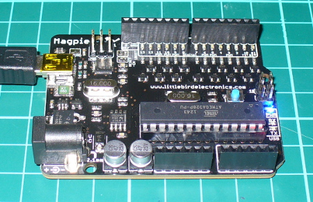
In this article we review the “Magpie” Arduino Uno-compatible board from Little Bird Electronics.

Introduction

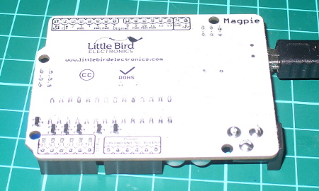
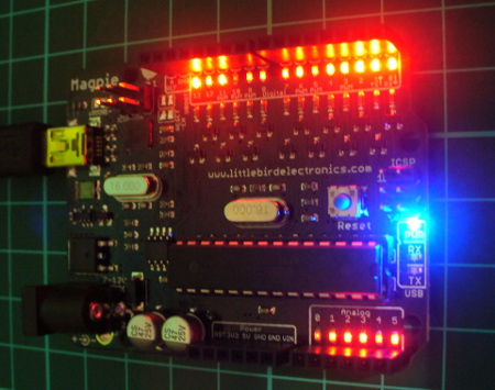
Finally I’m back at the office and have a pile of things to write about. Starting with the subject of this review – the “Magpie” board from Little Bird Electronics in Australia. It seems that a new Arduino-compatible board enters the market every week, thanks to the open-source nature of the platform and the availability of rapid manufacturing. However the Magpie isn’t just any old Arduino Uno knock-off, it has something which helps it stand out from the crowd – status LEDs on every digital and analogue I/O pin. You can see them between the stacking header sockets and the silk-screen labels. For example:

topss

and for the curious, the bottom of the Magpie:

bottomss

At first glance you might think “why’d they bother doing that? I could just wire up some LEDs myself”. True. However having them on the board speeds up the debugging process as you can see when an output is HIGH or LOW – and in the case of an input pin, whether a current is present or not. For the curious the LEDs are each controlled by a 2N7002 MOSFET with the gate connected to the I/O pin, for example:

mosfets

An LED will illuminate as long as the gate voltage is higher than the threshold voltage – no matter the status of the particular I/O pin. And if an I/O pin is left floating it may trigger the LED if the threshold voltage is exceeded at the gate. Therefore when using the Magpie it would be a good idea to set all the pins to LOW that aren’t required for your particular sketch. Even if you remove and reapply power the floating will still be prevalent, and indicated visually – for example:

float

Nevertheless you can sort that out in void setup(), and then the benefits of the LEDs become apparent. Consider the following quick demonstration sketch:

// LBE Magpie board LED demo - John Boxall 18 March 2013
// usual blink delay period
int d=100;
void setup()
{
 // digital pins to outputs
 for (int a=0; a<14; a++)
 {
 pinMode(a, OUTPUT);
 }
 pinMode(A0, OUTPUT);
 pinMode(A1, OUTPUT);
 pinMode(A2, OUTPUT);
 pinMode(A3, OUTPUT);
 pinMode(A4, OUTPUT);
 pinMode(A5, OUTPUT); 
}
void allOn()
// all LEDs on
{
 for (int a=0; a<14; a++)
 {
 digitalWrite(a, HIGH);
 }
 digitalWrite(A0, HIGH);
 digitalWrite(A1, HIGH);
 digitalWrite(A2, HIGH);
 digitalWrite(A3, HIGH);
 digitalWrite(A4, HIGH);
 digitalWrite(A5, HIGH);
}
void allOff()
// all LEDs on
{
 for (int a=0; a<14; a++)
 {
 digitalWrite(a, LOW);
 }
 digitalWrite(A0, LOW);
 digitalWrite(A1, LOW);
 digitalWrite(A2, LOW);
 digitalWrite(A3, LOW);
 digitalWrite(A4, LOW);
 digitalWrite(A5, LOW);
}
void clockWise(int r, int s)
// blinks on and off each LED clockwise
// r - # rotations, s - blink delay 
{
 allOff();
 for (int a=0; a<r; a++)
 {
 for (int b=13; b>=0; --b)
 {
 digitalWrite(b, HIGH);
 delay(s);
 digitalWrite(b, LOW);
 }
 digitalWrite(A5, HIGH);
 delay(s);
 digitalWrite(A5, LOW);
 digitalWrite(A4, HIGH);
 delay(s);
 digitalWrite(A4, LOW);
 digitalWrite(A3, HIGH);
 delay(s);
 digitalWrite(A3, LOW);
 digitalWrite(A2, HIGH);
 delay(s);
 digitalWrite(A2, LOW);
 digitalWrite(A1, HIGH);
 delay(s);
 digitalWrite(A1, LOW);
 digitalWrite(A0, HIGH);
 delay(s);
 digitalWrite(A0, LOW);
 delay(s);
 }
}
void anticlockWise(int r, int s)
// blinks on and off each LED anticlockwise
// r - # rotations, s - blink delay 
{
 allOff();
 for (int a=0; a<r; a++)
 {
 for (int b=0; b<14; b++)
 {
 digitalWrite(b, HIGH);
 delay(s);
 digitalWrite(b, LOW);
 }
 digitalWrite(A0, HIGH);
 delay(s);
 digitalWrite(A0, LOW);
 digitalWrite(A1, HIGH);
 delay(s);
 digitalWrite(A1, LOW);
 digitalWrite(A2, HIGH);
 delay(s);
 digitalWrite(A2, LOW);
 digitalWrite(A3, HIGH);
 delay(s);
 digitalWrite(A3, LOW);
 digitalWrite(A4, HIGH);
 delay(s);
 digitalWrite(A4, LOW);
 digitalWrite(A5, HIGH);
 delay(s);
 digitalWrite(A5, LOW);
 delay(s);
 }
}
void loop()
{
 anticlockWise(3,50);
 clockWise(3,50);
 for (int z=0; z<4; z++)
 {
 allOn();
 delay(100);
 allOff();
 delay(100);
 }
}

… and the results are demonstrated in the following video:

Apart from the LEDs the Magpie offers identical function to that of an Arduino Uno R2 – except the USB microcontroller is an Atmel 16U2 instead of an 8U2, and the USB socket is a mini-USB and not the full-size type.  For the curious you can download the Magpie design files from the product page.

Conclusion

If you’re often experimenting or working with the Arduino’s I/O pins and find yourself wiring up LEDs for testing purposes – the Magpie was made for you. Having those LEDs on the board really does save you if in a hurry to test or check something.

In the meanwhile have fun and keep checking into tronixstuff.com. Why not follow things on twitterGoogle+, subscribe  for email updates or RSS using the links on the right-hand column? And join our friendly Google Group – dedicated to the projects and related items on this website. Sign up – it’s free, helpful to each other –  and we can all learn something.

 The Magpie board used in this article was a promotional consideration supplied by Little Bird Electronics.

The post Review – LBE “Magpie” Arduino-compatible board appeared first on tronixstuff.

Mar
18

Introducing Goldilocks – the Arduino Uno-compatible with 1284p and uSD card

arduino, atmega1284p, atmel, bootloader, compatible, freetronics, goldilocks, kickstarter, pozible, tronixstuff, uno Comments Off on Introducing Goldilocks – the Arduino Uno-compatible with 1284p and uSD card 

[Update 19/03/2013 - the project is now fully funded. When the boards arrive we'll do a full review]

Introduction

It’s a solid fact that there are quite a few variations on the typical Arduino Uno-compatible board. You can get them with onboard wireless, GSM, Zigbee and more – however all with their own issues and specific purposes. But what if you wanted a board that was physically and electrically compatible with an Arduino Uno – but with much more SRAM, more EEPROM, more flash, more speed – and then some? Well that (hopefully) will be a possibility with the introduction of the “Goldilocks” board on Pozible by Phillip Stevens.

What’s Pozible?

Pozible is the Australian version of Kickstarter. However just like KS anyone with a credit card or PayPal can pledge and support projects.

What’s a Goldilocks board?

It’s a board based around the Atmel ATmega1284p microcontroller in an Arduino Uno-compatible physical board with a microSD card socket and a few extras. The use of the ’1284p gives us the following advantages over the Arduino Uno, including:

  • 16 kByte SRAM = 8x Uno SRAM – so that’s much more space for variables used in sketches – great for applications that use larger frame buffers such as Ethernet and image work;
  • 2 kByte EEPROM = 2 x Uno EEPROM – giving you more space for non-volatile data storage on the main board;
  • 128 kByte flash memory = 4 x Uno – giving you much, much more room for those larger sketches;
  • Two programmable USARTS – in other words, two hardware serial ports – no mucking about with SoftwareSerial and GSM or GPS shields;
  • Timer 3 – the ’1284p microcontroller has an extra 16-bit timer – timer 3, that is not present on any other ATmega microcontroller. Timer 3 does not have PWM outputs (unlike Timer 0, Timer 1, and Timer 2), and therefore is free to use as a powerful internal Tick counter, for example in a RTOS. freeRTOS has already been modified to utilise this Timer 3;
  • JTAG interface – yes – allowing more advanced developers the opportunity to debug their code;
  • better PWM access – the 1284p brings additional 8-bit Timer 2 PWM outputs onto PD, which creates the option for 2 additional PWM options on this port. It also removes the sharing of the important 16-bit PWM pins with the SPI interface, by moving them to PD4 & PD5, thus simplifying interface assignments;
  • Extra I/O pins – the 1284p has additional digital I/O pins on the PB port. These pins could be utilised for on-board Slave Select pins (for example), without stealing on-header digital pins and freeing the Arduino Pin 10 for Shield SPI SS use exclusively;

Furthermore the following design improvements over an Arduino Uno:

  • adding through-holes for all I/O – allowing you to solder directly onto the board whilst keeping header sockets;
  • replicate SPI and I2C for ease of use;
  • microSD card socket – that’s a no-brainer;
  • link the ATmega16u2 and ATmega1284p SPI interfaces – this will allow the two devices to work in concert for demanding multi-processing applications, involving USB and other peripherals;
  • Fully independent analogue pins, including seperate AVCC and GND – helps reduce noise on the ADC channels for improved analogue measurement accuracy;
  • move the reset button to the edge of the board – another no-brainer
  • clock the board at 20 MHz – that’s an extra 4 MHz over a Uno. And the use of a through hole precision crystal (not a SMD resonator) allows the use of after market timing choices, eg 22.1184 MHz for more accurate UART timings.

What does it look like? 

At the moment the board mock-up looks like this:

If funding is successful (and we hope it will be) the Goldilocks will be manufactured by the team at Freetronics. Apart from being a world-leader in Arduino-compatible hardware and systems, they’re the people behind the hardware for Ardusat and more – so we know the Goldilocks will be in good hands.

Will it really be compatible?

Yes – the Goldilocks will be shipped pre-programmed with an Arduino compatible boot-loader, and the necessary Board description files will be available to provide a 100% compatible Arduino IDE experience.

Conclusion

If you think this kind of board would be useful in your projects, you want to support a good project – or both, head over to Pozible and make your pledge. And for the record – I’ve put my money where my mouth is :)

Please note that I’m not involved in nor responsible for the Goldilocks project, however I’m happy to promote it as a worthwhile endeavour. In the meanwhile have fun and keep checking into tronixstuff.com. Why not follow things on twitterGoogle+, subscribe  for email updates or RSS using the links on the right-hand column? And join our friendly Google Group – dedicated to the projects and related items on this website. Sign up – it’s free, helpful to each other –  and we can all learn something.


Mar
18

Introducing Goldilocks – the Arduino Uno-compatible with 1284p and uSD card

arduino, atmega1284p, atmel, bootloader, compatible, freetronics, goldilocks, kickstarter, pozible, tronixstuff, uno Comments Off on Introducing Goldilocks – the Arduino Uno-compatible with 1284p and uSD card 

[Update 19/08/2013 - Exciting! Boards are shipping this week - review to follow!]

[Update 19/03/2013 - the project is now fully funded. Initial review here!]

Introduction

It’s a solid fact that there are quite a few variations on the typical Arduino Uno-compatible board. You can get them with onboard wireless, GSM, Zigbee and more – however all with their own issues and specific purposes. But what if you wanted a board that was physically and electrically compatible with an Arduino Uno – but with much more SRAM, more EEPROM, more flash, more speed – and then some? Well that (hopefully) will be a possibility with the introduction of the “Goldilocks” board on Pozible by Phillip Stevens.

What’s Pozible?

Pozible is the Australian version of Kickstarter. However just like KS anyone with a credit card or PayPal can pledge and support projects.

What’s a Goldilocks board?

It’s a board based around the Atmel ATmega1284p microcontroller in an Arduino Uno-compatible physical board with a microSD card socket and a few extras. The use of the ’1284p gives us the following advantages over the Arduino Uno, including:

  • 16 kByte SRAM = 8x Uno SRAM – so that’s much more space for variables used in sketches – great for applications that use larger frame buffers such as Ethernet and image work;
  • 2 kByte EEPROM = 2 x Uno EEPROM – giving you more space for non-volatile data storage on the main board;
  • 128 kByte flash memory = 4 x Uno – giving you much, much more room for those larger sketches;
  • Two programmable USARTS – in other words, two hardware serial ports – no mucking about with SoftwareSerial and GSM or GPS shields;
  • Timer 3 – the ’1284p microcontroller has an extra 16-bit timer – timer 3, that is not present on any other ATmega microcontroller. Timer 3 does not have PWM outputs (unlike Timer 0, Timer 1, and Timer 2), and therefore is free to use as a powerful internal Tick counter, for example in a RTOS. freeRTOS has already been modified to utilise this Timer 3;
  • JTAG interface – yes – allowing more advanced developers the opportunity to debug their code;
  • better PWM access – the 1284p brings additional 8-bit Timer 2 PWM outputs onto PD, which creates the option for 2 additional PWM options on this port. It also removes the sharing of the important 16-bit PWM pins with the SPI interface, by moving them to PD4 & PD5, thus simplifying interface assignments;
  • Extra I/O pins – the 1284p has additional digital I/O pins on the PB port. These pins could be utilised for on-board Slave Select pins (for example), without stealing on-header digital pins and freeing the Arduino Pin 10 for Shield SPI SS use exclusively;

Furthermore the following design improvements over an Arduino Uno:

  • adding through-holes for all I/O – allowing you to solder directly onto the board whilst keeping header sockets;
  • replicate SPI and I2C for ease of use;
  • microSD card socket – that’s a no-brainer;
  • link the ATmega16u2 and ATmega1284p SPI interfaces – this will allow the two devices to work in concert for demanding multi-processing applications, involving USB and other peripherals;
  • Fully independent analogue pins, including seperate AVCC and GND – helps reduce noise on the ADC channels for improved analogue measurement accuracy;
  • move the reset button to the edge of the board – another no-brainer
  • clock the board at 20 MHz – that’s an extra 4 MHz over a Uno. And the use of a through hole precision crystal (not a SMD resonator) allows the use of after market timing choices, eg 22.1184 MHz for more accurate UART timings.

What does it look like? 

At the moment the board mock-up looks like this:

If funding is successful (and we hope it will be) the Goldilocks will be manufactured by the team at Freetronics. Apart from being a world-leader in Arduino-compatible hardware and systems, they’re the people behind the hardware for Ardusat and more – so we know the Goldilocks will be in good hands.

Will it really be compatible?

Yes – the Goldilocks will be shipped pre-programmed with an Arduino compatible boot-loader, and the necessary Board description files will be available to provide a 100% compatible Arduino IDE experience.

Conclusion

If you think this kind of board would be useful in your projects, you want to support a good project – or both, head over to Pozible and make your pledge. And for the record – I’ve put my money where my mouth is :)

Please note that I’m not involved in nor responsible for the Goldilocks project, however I’m happy to promote it as a worthwhile endeavour. In the meanwhile have fun and keep checking into tronixstuff.com. Why not follow things on twitterGoogle+, subscribe  for email updates or RSS using the links on the right-hand column? And join our friendly Google Group – dedicated to the projects and related items on this website. Sign up – it’s free, helpful to each other –  and we can all learn something.

The post Introducing Goldilocks – the Arduino Uno-compatible with 1284p and uSD card appeared first on tronixstuff.

Introduction

In the same manner as their MSP430 development board, Texas Instruments also have another LaunchPad board with their powerful Stellaris LM4F120H5QR microcontroller. It’s an incredibly powerful and well-featured MCU – which offers an 80 MHz, 32-bit ARM Cortex-M4 CPU with floating point, 256 Kbytes of 100,000 write-erase cycle FLASH and many peripherals such as 1MSPS ADCs, eight UARTs, four SPIs, four I2Cs, USB & up to 27 timers, some configurable up to 64-bits.

That’s a bucket of power, memory and I/O for not much money – you can get the LaunchPad board for around $15. This LaunchPad has the in-circuit debugger, two user buttons, an RGB LED and connectors for I/O and shield-like booster packs:

and the other side:

However the good news as far as we’re concerned is that you can now use it with the Energia Arduino-compatible IDE that we examined previously. Before rushing out to order your own Stellaris board, install Energia and examine the available functions and libraries to make sure you can run what you need. And if so, you’re set for some cheap Arduino power.

Installation

Installation is simple, just get your download from here. If you’re running Windows 7 – get the USB drivers from here. When you plug your LaunchPad into the USB for the first time, wait until after Windows attempts to install the drivers, then install drivers manually after download via Device manager … three times (JTAG, virtual serial port and DFU device). Use the debug USB socket (and set the switch to debug) when installing and uploading code. If you get the following warning from Windows, just click “Install this driver software anyway”:

Once the drivers are installed, plug in your LaunchPad, wait a moment – then run Energia. You can then select your board type and serial port just like the Arduino IDE. Then go ahead and upload the “blink” example…

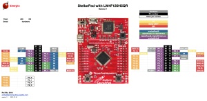
Awesome – check out all that free memory space. In the same manner as the MSP430, there are some hardware<>sketch differences you need to be aware of. For example, how to refer to the I/O pins in Energia? A map has been provided for front:

… and back:

As you can imagine, the Stellaris MCUs are different to an AVR, so a lot of hardware-specific code doesn’t port over from the world of Arduino. One of the first things to remember is that the Stellaris is a 3.3V device. Code may or may not be interchangeable, so a little research will be needed to match up the I/O pins and rewrite the sketch accordingly. For example, instead of digital pins numbers, you use PX_Y - see the map above. So let’s say you want to run through the RGB LED… consider the following sketch:

int wait = 500;
void setup() 
{ 
 // initialize the digital pin as an output.
 pinMode(PF_1, OUTPUT); // red 
 pinMode(PF_3, OUTPUT); // green
 pinMode(PF_2, OUTPUT); // blue
}
void loop() 
{
 digitalWrite(PF_1, HIGH); 
 delay(wait); 
 digitalWrite(PF_1, LOW); 
 digitalWrite(PF_3, HIGH); 
 delay(wait); 
 digitalWrite(PF_3, LOW); 
 digitalWrite(PF_2, HIGH); 
 delay(wait); 
 digitalWrite(PF_2, LOW); 
}

Which simply blinks the red, green and blue LED elements in series. Using digital inputs is in the same vein, and again the buttons are wired so when pressed they go LOW. An example of this in the following sketch:

void setup() 
{ 
 // initialize the digital pins
 pinMode(PF_1, OUTPUT); // red 
 pinMode(PF_3, OUTPUT); // green
 pinMode(PF_2, OUTPUT); // blue

 pinMode(PF_4, INPUT_PULLUP); // left - note _PULLUP
 pinMode(PF_0, INPUT_PULLUP); // right - note _PULLUP 
}
void blinkfast() 
{
 for (int i=0; i<10; i++)
 {
 digitalWrite(PF_1, HIGH); 
 delay(250); 
 digitalWrite(PF_1, LOW); 
 digitalWrite(PF_3, HIGH); 
 delay(250); 
 digitalWrite(PF_3, LOW); 
 digitalWrite(PF_2, HIGH); 
 delay(250); 
 digitalWrite(PF_2, LOW); 
 }
}
void blinkslow() 
{
 for (int i=0; i<5; i++)
 {
 digitalWrite(PF_1, HIGH); 
 delay(1000); 
 digitalWrite(PF_1, LOW); 
 digitalWrite(PF_3, HIGH); 
 delay(1000); 
 digitalWrite(PF_3, LOW); 
 digitalWrite(PF_2, HIGH); 
 delay(1000); 
 digitalWrite(PF_2, LOW); 
 }
}
void loop()
{
 if (digitalRead(PF_4)==LOW) { blinkslow(); }
 if (digitalRead(PF_0)==LOW) { blinkfast(); }
}

And for the non-believers:

Where to from here? 

Sometimes you can be platform agnostic, and just pick something that does what you want with the minimum of time and budget. Or to put it another way, if you need a fast CPU and plenty of space but couldn’t be bothered don’t have time to work with Keil, Code Composer Studio, IAR etc – the Energia/Stellaris combination could solve your problem. There’s a growing Energia/Stellaris forum, and libraries can be found here. At the time of writing we found an I2C library as well.

However to take full advantage of the board, consider going back to the TI tools and move forward with them. You can go further with the tutorials and CCS etc from Texas Instruments own pages.

In the meanwhile have fun and keep checking into tronixstuff.com. Why not follow things on twitterGoogle+, subscribe  for email updates or RSS using the links on the right-hand column? And join our friendly Google Group – dedicated to the projects and related items on this website. Sign up – it’s free, helpful to each other –  and we can all learn something.


Introduction

In the same manner as their MSP430 development board, Texas Instruments also have another LaunchPad board with their powerful Stellaris LM4F120H5QR microcontroller. It’s an incredibly powerful and well-featured MCU – which offers an 80 MHz, 32-bit ARM Cortex-M4 CPU with floating point, 256 Kbytes of 100,000 write-erase cycle FLASH and many peripherals such as 1MSPS ADCs, eight UARTs, four SPIs, four I2Cs, USB & up to 27 timers, some configurable up to 64-bits.

That’s a bucket of power, memory and I/O for not much money – you can get the LaunchPad board for around $15. This LaunchPad has the in-circuit debugger, two user buttons, an RGB LED and connectors for I/O and shield-like booster packs:

and the other side:

However the good news as far as we’re concerned is that you can now use it with the Energia Arduino-compatible IDE that we examined previously. Before rushing out to order your own Stellaris board, install Energia and examine the available functions and libraries to make sure you can run what you need. And if so, you’re set for some cheap Arduino power.

Installation

Installation is simple, just get your download from here. If you’re running Windows 7 – get the USB drivers from here. When you plug your LaunchPad into the USB for the first time, wait until after Windows attempts to install the drivers, then install drivers manually after download via Device manager … three times (JTAG, virtual serial port and DFU device). Use the debug USB socket (and set the switch to debug) when installing and uploading code. If you get the following warning from Windows, just click “Install this driver software anyway”:

Once the drivers are installed, plug in your LaunchPad, wait a moment – then run Energia. You can then select your board type and serial port just like the Arduino IDE. Then go ahead and upload the “blink” example…

stellarisblink

Awesome – check out all that free memory space. In the same manner as the MSP430, there are some hardware<>sketch differences you need to be aware of. For example, how to refer to the I/O pins in Energia? A map has been provided for front:

stellarpad-e28094-pins-maps1

… and back:

stellarpad-back-e28094-pins-maps1

As you can imagine, the Stellaris MCUs are different to an AVR, so a lot of hardware-specific code doesn’t port over from the world of Arduino. One of the first things to remember is that the Stellaris is a 3.3V device. Code may or may not be interchangeable, so a little research will be needed to match up the I/O pins and rewrite the sketch accordingly. For example, instead of digital pins numbers, you use PX_Y - see the map above. So let’s say you want to run through the RGB LED… consider the following sketch:

int wait = 500;
void setup() 
{ 
 // initialize the digital pin as an output.
 pinMode(PF_1, OUTPUT); // red 
 pinMode(PF_3, OUTPUT); // green
 pinMode(PF_2, OUTPUT); // blue
}
void loop() 
{
 digitalWrite(PF_1, HIGH); 
 delay(wait); 
 digitalWrite(PF_1, LOW); 
 digitalWrite(PF_3, HIGH); 
 delay(wait); 
 digitalWrite(PF_3, LOW); 
 digitalWrite(PF_2, HIGH); 
 delay(wait); 
 digitalWrite(PF_2, LOW); 
}

Which simply blinks the red, green and blue LED elements in series. Using digital inputs is in the same vein, and again the buttons are wired so when pressed they go LOW. An example of this in the following sketch:

void setup() 
{ 
 // initialize the digital pins
 pinMode(PF_1, OUTPUT); // red 
 pinMode(PF_3, OUTPUT); // green
 pinMode(PF_2, OUTPUT); // blue

 pinMode(PF_4, INPUT_PULLUP); // left - note _PULLUP
 pinMode(PF_0, INPUT_PULLUP); // right - note _PULLUP 
}
void blinkfast() 
{
 for (int i=0; i<10; i++)
 {
 digitalWrite(PF_1, HIGH); 
 delay(250); 
 digitalWrite(PF_1, LOW); 
 digitalWrite(PF_3, HIGH); 
 delay(250); 
 digitalWrite(PF_3, LOW); 
 digitalWrite(PF_2, HIGH); 
 delay(250); 
 digitalWrite(PF_2, LOW); 
 }
}
void blinkslow() 
{
 for (int i=0; i<5; i++)
 {
 digitalWrite(PF_1, HIGH); 
 delay(1000); 
 digitalWrite(PF_1, LOW); 
 digitalWrite(PF_3, HIGH); 
 delay(1000); 
 digitalWrite(PF_3, LOW); 
 digitalWrite(PF_2, HIGH); 
 delay(1000); 
 digitalWrite(PF_2, LOW); 
 }
}
void loop()
{
 if (digitalRead(PF_4)==LOW) { blinkslow(); }
 if (digitalRead(PF_0)==LOW) { blinkfast(); }
}

And for the non-believers:

Where to from here? 

Sometimes you can be platform agnostic, and just pick something that does what you want with the minimum of time and budget. Or to put it another way, if you need a fast CPU and plenty of space but couldn’t be bothered don’t have time to work with Keil, Code Composer Studio, IAR etc – the Energia/Stellaris combination could solve your problem. There’s a growing Energia/Stellaris forum, and libraries can be found here. At the time of writing we found an I2C library as well.

However to take full advantage of the board, consider going back to the TI tools and move forward with them. You can go further with the tutorials and CCS etc from Texas Instruments own pages.

In the meanwhile have fun and keep checking into tronixstuff.com. Why not follow things on twitterGoogle+, subscribe  for email updates or RSS using the links on the right-hand column? And join our friendly Google Group – dedicated to the projects and related items on this website. Sign up – it’s free, helpful to each other –  and we can all learn something.

The post Exploring the TI Stellaris platform with Energia Arduino-compatible IDE appeared first on tronixstuff.

Introduction

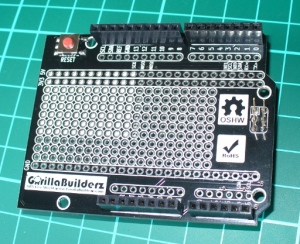
Some of you may be using an Arduino Leonardo board, taking advantage of the newer ATmega32U4 microcontroller for various reasons. And rightly so – there’s the extra analogue I/O, virtual USB and the microUSB socket so you can use your phone charger cable. However with the new microcontroller comes a few changes to the board pinouts – I2C and SPI have moved. So if you have a nice Ethernet shield or something using I2C – you’re basically out of luck… until now. The problem has been solved nicely by the team at GorillaBuilderz have created their LeoShield:

Use

You simply place it on the Leonardo, and then the older legacy shield on top. The LeoShield redirects the I2C pins back to A4 and A5, and also sends the SPI lines back to D11~D13. For example, our Ethernet shield:

The ICSP pins are also extended from the Leonardo to the LeoShield, for example:

however when inserting the LeoShield into your Leonardo, take care lining up all the pins before pushing the shield down. There is also the large prototyping area which has 5V , 3.3V and GND rails across the full width for convenience. The sticker on the rear of the shield is to insulate against any large items that may come in contact from the host board, however you can peel it off to realise the complete prototyping space.

Conclusion

It’s simple and it works – so if you need to use an older Arduino shield with a Leonardo the choice is simple – get yourself a Leoshield.

Disclaimer - The Leoshield was a review product received from GorillaBuilderz.

Thanks for reading tronixstuff.com. I’ve got some new tutorials coming up very soon, and a lot of existing posts are curently being updated – so follow things on twitterGoogle+, subscribe  for email updates or RSS using the links on the right-hand column. And join our friendly Google Group – dedicated to the projects and related items on this website. Sign up – it’s free, helpful to each other –  and we can all learn


Introduction

Some of you may be using an Arduino Leonardo board, taking advantage of the newer ATmega32U4 microcontroller for various reasons. And rightly so – there’s the extra analogue I/O, virtual USB and the microUSB socket so you can use your phone charger cable. However with the new microcontroller comes a few changes to the board pinouts – I2C and SPI have moved. So if you have a nice Ethernet shield or something using I2C – you’re basically out of luck… until now. The problem has been solved nicely by the team at GorillaBuilderz have created their LeoShield:

Use

You simply place it on the Leonardo, and then the older legacy shield on top. The LeoShield redirects the I2C pins back to A4 and A5, and also sends the SPI lines back to D11~D13. For example, our Ethernet shield:

The ICSP pins are also extended from the Leonardo to the LeoShield, for example:

however when inserting the LeoShield into your Leonardo, take care lining up all the pins before pushing the shield down. There is also the large prototyping area which has 5V , 3.3V and GND rails across the full width for convenience. The sticker on the rear of the shield is to insulate against any large items that may come in contact from the host board, however you can peel it off to realise the complete prototyping space.

Conclusion

It’s simple and it works – so if you need to use an older Arduino shield with a Leonardo the choice is simple – get yourself a Leoshield.

leoleoshieldsmall

Disclaimer - The Leoshield was a review product received from GorillaBuilderz.

Thanks for reading tronixstuff.com. I’ve got some new tutorials coming up very soon, and a lot of existing posts are curently being updated – so follow things on twitterGoogle+, subscribe  for email updates or RSS using the links on the right-hand column. And join our friendly Google Group – dedicated to the projects and related items on this website. Sign up – it’s free, helpful to each other –  and we can all learn

The post Review: GorillaBuilderz LeoShield appeared first on tronixstuff.


  • Newsletter

    Sign up for the PlanetArduino Newsletter, which delivers the most popular articles via e-mail to your inbox every week. Just fill in the information below and submit.

  • Like Us on Facebook