At the risk of putting too fine a point on it, Hackaday exists because people are out there building and documenting open source gadgets. If the person who built a particular gizmo is willing to show the world how they did it, consider us interested. Since you’re reading this, we’ll assume you are as well. Over the years, this mentality has been spreading out from the relatively niche hacker community into the greater engineering world, and we couldn’t be happier.
Case in point, the Poseidon project created at the California Institute of Technology. Developed by students [Sina Booeshaghi], [Eduardo Beltrame], and [Dylan Bannon], along with researcher [Jase Gehring] and professor [Lior Pachter], Poseidon consists of an open source digital microscope and syringe pump which can be used for microfluidics experiments. The system is not only much cheaper than commercial offerings, but is free from the draconian modification and usage restrictions that such hardware often comes with.
Of course, one could argue that major labs have sufficient funding to purchase this kind of gear without having to take the DIY route. That’s true enough, but what benefit is there to limiting such equipment to only the established institutions? As in any other field, making the tools available to a wider array of individuals (from professionals to hobbyists alike) can only serve to accelerate progress and move the state of the art forward.
The Poseidon microscope consists of a Raspberry Pi, touch screen module, and commercially available digital microscope housed in a 3D printed stage. This device offers a large and clear view of the object under the microscope, and by itself makes an excellent educational tool. But when running the provided Python software, it doubles as a controller for the syringe pumps which make up the other half of the Poseidon system.
Almost entirely 3D printed, the pumps use commonly available components such as NEMA 17 stepper motors, linear bearings, and threaded rods to move the plunger on a syringe held in the integrated clamp. Controlled by an Arduino and CNC shield, these pumps are able to deliver extremely precise amounts of liquid which is critical for operations such as Single-cell RNA sequencing. All told a three pump system can be built for less than $400 USD, compared to the tens of thousands one might pay for commercially available alternatives.
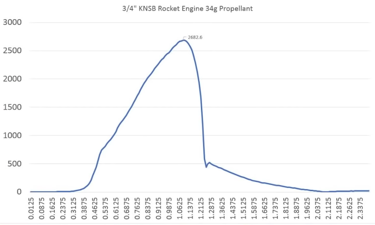
If you’re into amateur rocketry, you pretty quickly outgrow the dinky little Estes motors that they sell in the toy stores. Many hobbyists move on to building their own homebrew solid rocket motors and experimenting with propellant mixtures, but it’s difficult to know if you’re on the right track unless you have a way to quantify the thrust you’re getting. [ElementalMaker] decided he’d finally hit the point where he needed to put together a low-cost test stand for his motors, and luckily for us decided to document the process and the results.
The heart of the stand is a common load cell (the sort of thing you’d find in a digital scale) coupled with a HX711 amplifier board mounted between two plates, with a small section of vertical PVC pipe attached to the topmost plate to serve as a motor mount. This configuration is capable of measuring up to 10 kilograms with an 80Hz sample rate, which is critically important at this type of rocket motors only burn for a few seconds to begin with. The sensor produces hundreds of data points during the short duration of the build, which is perfect for graphing the motor’s thrust curve over time.
Given such a small window in which to make measurements, [ElementalMaker] didn’t want to leave anything to chance. So rather than manually igniting the motor and triggering the data collection, the stand’s onboard Arduino does both automatically. Pressing the red button on the stand starts a countdown procedure complete with flashing LED, after which a relay is used to energize a nichrome wire “electronic match” stuck inside the motor.
In the video after the break you can see that [ElementalMaker] initially had some trouble getting the Arduino to fire off the igniter, and eventually tracked the issue down to an overabundance of current that was blowing the nichrome wire too fast. Swapping out the big lead acid battery he was originally using with a simple 9V battery solved the problem, and afterwards his first test burns on the stand were complete successes.
We were glued to our screens last month as NASA successfully landed the InSight module on Mars. (Bet you were, too.) What an amazing sight a Martian sunrise turns out to be! Now, we’ve got the bug. The bigtime Space Bug. Accordingly, our final Humble Bundle ebook deal of […]
Lab equipment is often expensive, but budgets can be tight and not always up to getting small labs or researchers what they need. That’s why [akshay_d21] designed an Open Source Lab Rocker with a modular tray that uses commonly available hardware and 3D printed parts. The device generates precisely controlled, smooth motion to perform automated mild to moderately aggressive mixing of samples by tilting the attached tray in a see-saw motion. It can accommodate either a beaker or test tubes, but since the tray is modular, different trays can be designed to fit specific needs.
DIY lab equipment really benefits from the recent growth in desktop manufacturing and part availability; this one is in good company along with the DIY Laboratory Dry Bath and this DIY Syringe Pump.
Damon McMillan built a robotic boat. Not just any robotic boat. This one is sailing across the world's oceans. And it's just simple and elegant enough to work.
[Mr_GreenCoat] is studying engineering. His thermodynamics teacher agreed with the stance that engineering is best learned through experimentation, and tasked [Mr_GreenCoat]’s group with the construction of a vacuum chamber to prove that the boiling point of a liquid goes down with the pressure it is exposed to.
His group used black PVC pipe to construct their chamber. They used an air compressor to generate the vacuum. The lid is a sheet of lexan with a silicone disk. We’ve covered these sorts of designs before. Since a vacuum chamber is at max going to suffer 14.9 ish psi distributed load on the outside there’s no real worry of their design going too horribly wrong.
The interesting part of the build is the hardware and software built to boil the water and log the temperatures and pressures. Science isn’t done until something is written down after all. They have a power resistor and a temperature probe inside of the chamber. The temperature over time is logged using an Arduino and a bit of processing code.
In the end their experiment matched what they had been learning in class. The current laws of thermodynamics are still in effect — all is right in the universe — and these poor students can probably save some money and get along with an old edition of the textbook. Video after the break.
Planet Arduino is, or at the moment is wishing to become, an aggregation of public weblogs from around the world written by people who develop, play, think on Arduino platform and his son. The opinions expressed in those weblogs and hence this aggregation are those of the original authors. Entries on this page are owned by their authors. We do not edit, endorse or vouch for the contents of individual posts. For more information about Arduino please visit www.arduino.cc
You are currently browsing the archives for the science category.

 Central Florida Maker groups use their diverse skills to create an interactive Bumblebee costume in only 3 weeks for a Magic Wheelchair recipient.