Posts | Comments

Planet Arduino

Archive for the ‘LED display’ Category

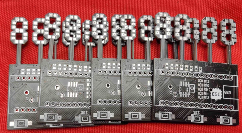
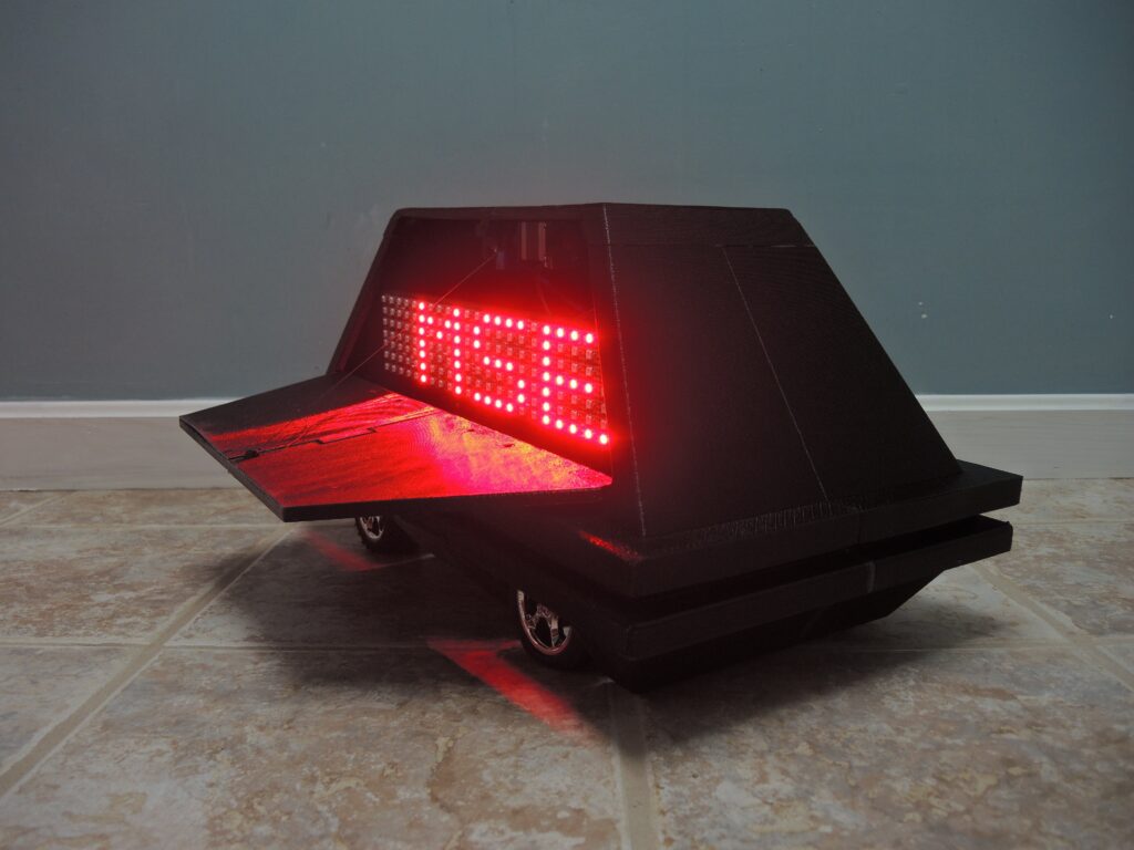
Of course, there’s nothing unusual about using 7-segment displays, especially in a clock. However, [Edison Science Corner] didn’t buy displays. Instead, he fabricated them from a PCB using 0805 LEDs for the segments. You can see the resulting clock project in the video below.

While the idea is good, we might have been tempted to use a pair of LEDs for each segment or used a diffuser to blur the LEDs. The bare look is nice, but it can make reading some numerals slightly confusing.

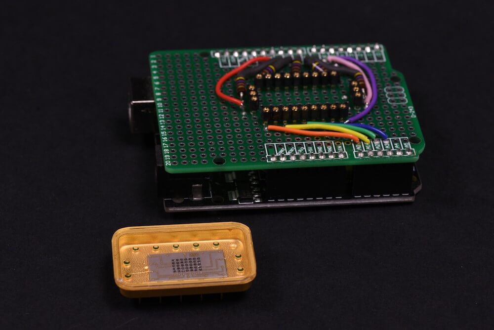
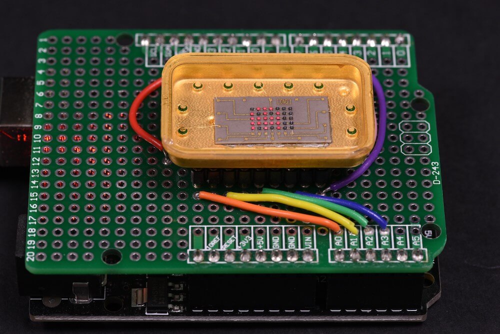
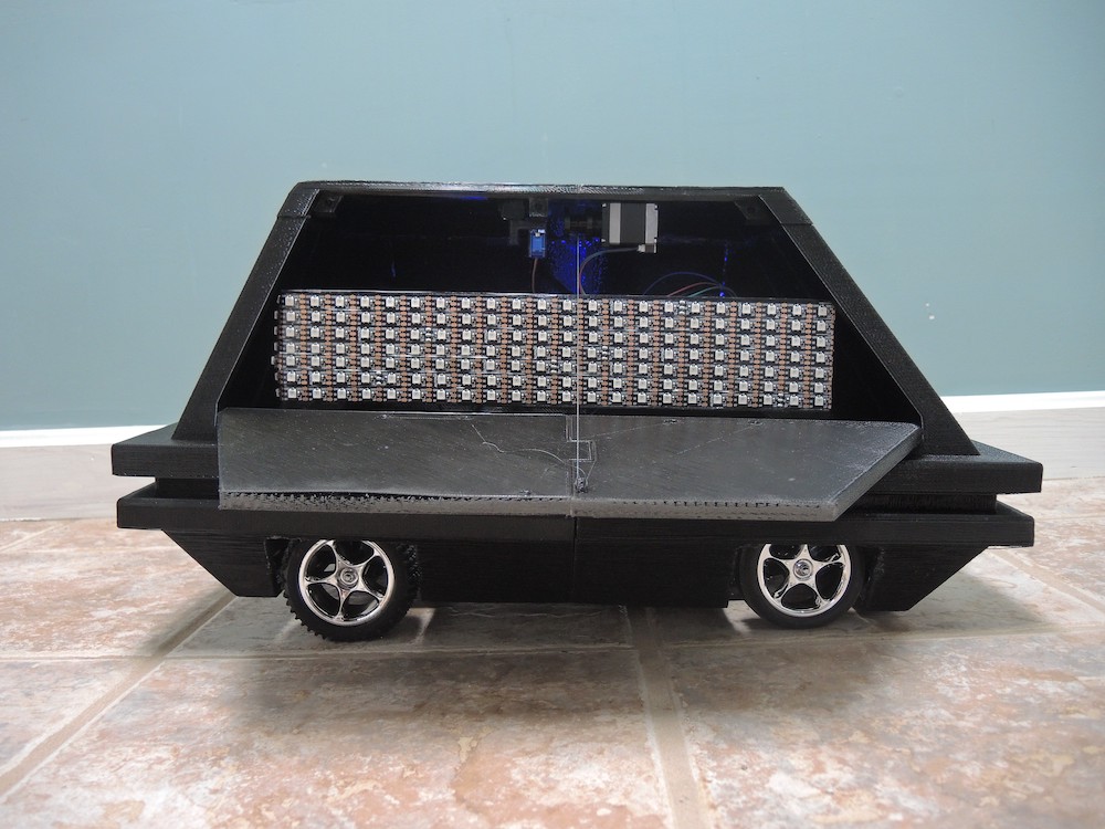
The remainder of the project is what you’d expect, a 3D-printed case and an Arduino Nano coupled with a DS1307 make the clock part work.

Honestly, with a few changes, we’d like to make up some of these boards for other kinds of custom displays. We can imagine a PCB where the bottoms of the display elements are right at the edge of the board instead of on stalks. You could even create a 14-segment display (we used to call these British flag displays) to make custom text messages. Of course, you can also make custom electroluminescent displays on a PCB reasonably easily, too.

What does one do with over 1,000 LEDs, white acrylic, and 288 IR sensors? If you’re Redditor “jordy_essen,” you create an interactive light panel.

In one mode, the user pull a reflective tool across the sensors to draw a paths, with potentiometers implemented to select the color. It can also be set up to play a sort of whack-a-mole game, where one has to activate the sensor in the same area where it illuminates.

For this amazing device, jordy_essen uses not one, or even two, but six Arduino Mega boards to drive the LEDs directly — in turn controlled by a webpage running on a Raspberry Pi. If that wasn’t enough hardware, an Uno is tasked with taking inputs from the color potentiometers. 

It’s a brilliant project in any sense of the word!

If you need another idea for how to creatively diffuse LED lighting, then look no further than the “Light Me Up!” project by Hyewon Shin, Eunjeong Ko, and Junsung Yi. 

Their setup uses 312 3D-printed and laser-cut light triangles, each of which contains a trio of RGB LEDs. Users select the desired light by pressing the triangles themselves, via buttons concealed beneath the main assembly. Several Arduino boards are used to control the massive structure.

With such an involved triangular display, a number of interesting 3D-like shapes and even words can be created by users. Alternatively, smaller triangle arrangements can also be constructed using the same build concepts. 

This project has several triangles that form a hexagonal shape. So you can create stereoscopic patterns according to how you design light! Just press each piece and various colors will be gradated, and when the color you want comes out, just hit the hand you pressed and it will continue to shine beautifully with the color you wanted!

Check out its triangular luminescence in the videos below!

Patrick Hickey has been collecting retro LED indicators and displays for decades, and his rarest item is an HP 5082-7002—a 5×7 dot matrix LED display in a beautiful gold and (possibly) sapphire enclosure. This device is so rare, in fact, that he believes it to be a prototype, somehow relegated to eBay for gold salvage.

Hickey wasn’t able to find any reference to the unit—much less a datasheet—even after extensive research. Instead, he went to work reverse engineering the HP 5082-7002 following the tracks of the PCB to work out how the rows and columns are connected. 

He then designed a test shield for an Arduino Uno with sockets on which the mystery device could sit. With this piece of hardware built, he can now create simple pictures and animated sprites on it using pulsed Arduino outputs.

I followed the tracks to work out which pins are connected rows and columns, and set out to build a test shield for an Arduino Uno.  I decided to drive them as “rows” of 5. The max output of Arduino I/O pins is rated at 40mA, so in theory, I could simultaneously power up to 5 LEDs in parallel at 8mA using 1 pin. In practice, using strobe/multiplexing, the duty cycle is much less: 1/7 or 1/5 depending if you drive by rows (7) or columns (5) respectively. The 5 current limiting series resistors are 470 Ohms (¼ Watt). My preference is to use carbon composition resistors (e.g. Allen Bradley). I love the “retro look” of them and I think they compliment the vintage LEDs.  

I had already written Arduino code for testing some TIL-305 matrix displays, so it was relatively simple to transpose the pins in my sketch for this configuration. The test code permits animations of up to 150 different alphanumeric characters/symbols, and (of course) some animated sprites inspired by retro video games.

In several iterations of the Star Wars saga, small black droids can be seen scurrying around imperial installations. While they tend to fade into the background or provide a fun distraction in the movies, the mouse droid by Potent Printables acts as a sort of physical messaging app. It’s able to travel to the correct location, then pop open to unveil a scrolling LED sign.

Potent Printables can trigger the side door using a Bluetooth app on his phone. On command, an RC servo pushes it open, and lowers it down using a stepper motor/reel setup. An Arduino Uno along with an Adafruit Motor Shield are used for control, while an HC-05 module enables communication with the system.  

Check out the latest video in this build series below!

Most people support their school or favorite sports team by buying a shirt or tuning into games. Jacob Thompson, however, took things one step further and created his own Arduino-powered, backlit Clemson Tiger Paw.

Thompson’s “WallPaw,” as he calls it, uses an Arduino Uno to receive signals from an infrared remote and to pick up sounds with a small microphone. This information is passed on to an Arduino Mega, which controls a five-meter-long strip of WS2812 LEDs to provide lighting effects.

He notes that it would be possible to use only one Arduino board for everything, but patterned his code after this tutorial that included two. The paw itself is cut out of wood and clear acrylic, allowing the lights underneath to shine through nicely.

You can see the build in action below and find more details on Thompson’s website here.

John Edgar Park builds a giant 7-segment display timer for a Ninja obstacle course.

Read more on MAKE

The post Who on Earth Needs a Ninja Timer? appeared first on Make: DIY Projects and Ideas for Makers.

[Hari Waguna] wanted to build a computerized Sudoku game. Ordinarily, that wouldn’t be a big deal. You can buy one, of course, but what fun is that? There’s plenty of apps for phones, but again, not much of a challenge. If you want to preserve your hacker cred, you’d use a CPU board like an Arduino or a Raspberry Pi with an LCD screen, right? But if you want to grow your hacker cred, you’d follow [Hari’s] lead and use 81 seven-segment displays and a membrane keyboard.

Driving that many displays takes some doing (in this case shift registers). [Hari] uses some other tricks, like reading the keyboard using a single pin (and a resistor network). He’s made several videos about the project, including the one below.

The PCB measures eight inches by a little over five inches. Maybe that’s handheld. Practical? Probably not. Cool? Undeniably.

We’ve seen something similar before, although perhaps not as compact. If you really want street cred, you can always try nixie tubes.


Filed under: Arduino Hacks

Have you ever wanted to have a light show that reacts to what you play through you’re favorite electric instrument? Georgia Tech grad student Wil Roberts has, and so he created a guitar-controlled LED display–an impressive project that combines both his Maker and musical chops.

To accomplish this, Roberts used an Arduino Uno along with an Adafruit 16×32 RGB LED matrix panel that responds to the guitar’s signal. The bottom rows are always blue, while the top ones progress from green to red the louder he shreds. The top rows remain red depending on the length of the note being played.

Want one of your own? Roberts has made all of the display’s circuitry and code available on Instructables. In the meantime, be sure to see it in action below!

3DPClock-5Building your own clock is practically a rite of passage as a Maker. 3D-print this Arduino-based desktop clock with a jumbo seven-segment LED display that glows from within.

Read more on MAKE

The post 3D Print a Supersized Seven-Segment Clock appeared first on Make: DIY Projects, How-Tos, Electronics, Crafts and Ideas for Makers.


  • Newsletter

    Sign up for the PlanetArduino Newsletter, which delivers the most popular articles via e-mail to your inbox every week. Just fill in the information below and submit.

  • Like Us on Facebook