Posts | Comments

Planet Arduino

Archive for the ‘LeoStick’ Category

Jun
11

Kit review – the Freetronics CUBE4: RGB LED Cube

4x4x4, arduino, argot, cube, freetronics, jaycar, kit, kit review, LED, leonardo, LeoStick, review, RGB, XC4274 Comments Off on Kit review – the Freetronics CUBE4: RGB LED Cube 

Introduction

LED cubes are a fascinating item, no matter where you come from the allure of blinking LEDs in various patterns is always attractive. And making your own is a fun challenge that most people can do after some experience with electronics hardware. However most people use single-colour LEDs, as wiring up RGB units triples the complexity of the circuit. Until now.

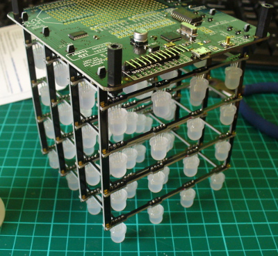
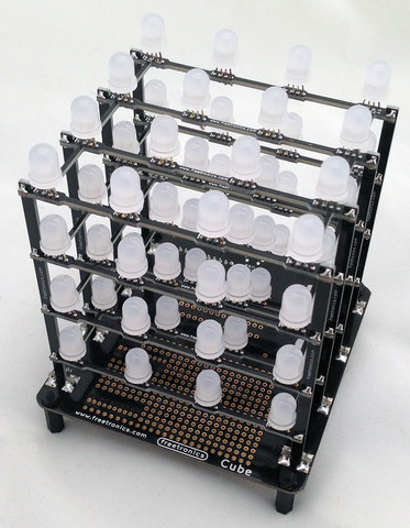
After much anticipation Freetronics have released their CUBE4 RGB LED cube kit – a simple to assemble and completely-customisable RGB LED cube:

cube4off

Unlike other cubes on the market, this one includes an on-board ATmega32u4 microcontroller with Arduino Leonardo-compatible bootloader and a microUSB socket (… and a lot more) – so you don’t need anything extra to get started. And this gives you many more options when you’re ready to expand. But first let’s put it together and then get it working. Furthermore, keep reading to find out how you can have a chance to win your own Cube4.

Assembly

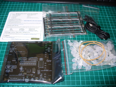
Inside the box are all the parts needed for the kit, even a microUSB cable to power the Cube4 and also communicate with it:

parts

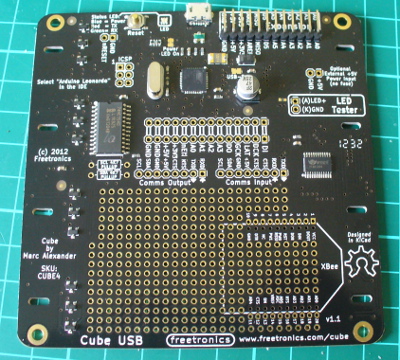
There’s 64 RGB LEDs in that bag, so get ready for some soldering. The base PCB is well laid out, labelled and gives you an idea for the expansion possibilities:

PCBtop

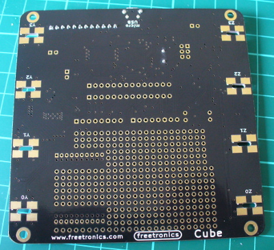
Plenty of room to add your own circuitry – and the bottom:

PCBbottom

As you can see in the image above, there’s an XBee-compatible pinout if you want to add communication via wirless serial link, plenty of prototyping space for your own additions and many other ports are brought out to open pads. There’s even a 5V supply pair to test LEDs, and a blue “power on” LED (which can be deactivated if necessary by cutting a track on the PCB).

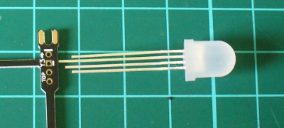
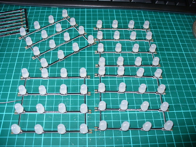
The first job is to mount the LEDs on their plane PCBs – there are four, one for each horizontal plant. It’s very important to get the LEDs in the right way round, and there’s markers on the PCB that you can match up the longest leg of the LED with:

LEDinsertdirection

From experience I found it best to insert all the LEDs:

LEDsinserted

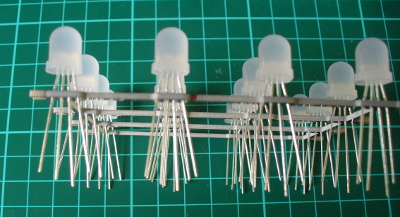
…and then do a final mass check of the alignment – which is easy if you hold the plane up to one side and compare the legs, for example:

checkLEDdirection

At this stage it’s a great idea to double-check your LED alignment. After a while you’ll have the LEDs soldered in and trimmed nicely:

LEDssoldered

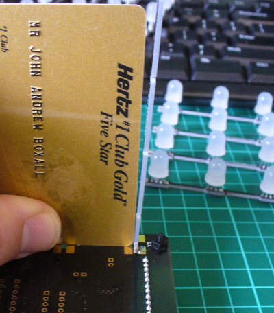
The next step was getting the vertical sticks aligned in order to hold the LED planes (above). Each stick is for a particular spot on the PCB so check the label on the stick matches the hole on the PCB. It’s incredibly important to make sure you have them perfectly perpendicular to the PCB, so find something like a square-edge or card to help out:

alignstick

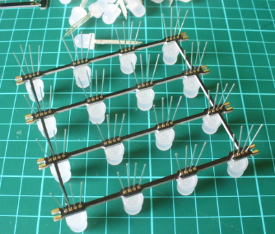
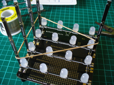
Once you have a row of sticks in you can start with a plane then insert a stick on the other side, for example:

firstplanerubberband

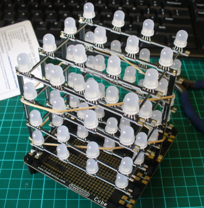
Note the use of the elastic band to hold things together – they really help. Then it’s a simple matter of adding the planes and holding it together with another band:

fourplanespresolder

… at which point you can do a final check that all the planes and sticks are inserted correctly. Then solder all the copper spots together and you’re done.

Don’t forget to turn the cube upside-down as there’s soldering to be done on the bottom of the planes as well:

solderupsidedownaswell

 Although it might look a little scary, the final assembly isn’t that difficult – just take your time so it’s right the first time. You can view the following video which describes the entire process:

Once you’re confident that all the soldering has been completed – double-check for joints that aren’t completely bridged with solder as they will affect the operation of the cube. Then you can plug in the USB cable and watch the preloaded test/demonstration sketch in action:

If all your LEDs are working, awesome. If not – check the soldering. If there’s still some rogues – check your individual LEDs. Some of you are probably thinking “well that isn’t too colourful” – the problem is the camera, not the Cube4. If you see it in real life, it’s much better.

Operation

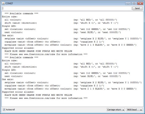
There are two methods of controlling the Cube4. It is delivered with a preloaded sketch that runs the demonstration showed in the video above, and then accepts commands over a serial/USB connection. So you can simply plug it in, fire up a terminal program (or the Arduino IDE serial monitor) and send text commands to do various things. If you type “help ;” the syntax is returned which explains how you can do things (click image to enlarge):

helpscreen

This serial control mode allows control by any type of software that can write to a serial port. Furthermore any other external hardware that can create or introduce serial text can also control the Cube4. For example by mounting an XBee module underneath and linking it to the TX/RX lines gives you a wireless Cube4. By doing so you can control it with a Raspberry Pi or other system.

Furthermore the Cube4 is also an Arduino Leonardo-compatible board in the same way as a Freetronics LeoStick.  With the use of the Cube4 Arduino library you can then create your own sketches which can visualise data with very simple to use functions for the Cube4. There are some great example sketches with the library for some inspiration and fun. Over time I look forward to using the Cube4 in various ways, including adding an Electric Imp IoT device and making another clock (!).

Competition

Would you like the chance to win a Cube4? It’s easy. Clearly print your email address on a postcard, and mail it to:

CUBE4 Competition, PO Box 5435, Clayton 3168, Australia

Entries must be received by the 30th of  July 2013. One postcard will then be drawn at random, and the winner will receive one Cube4 delivered by Australia Post standard air mail. You can enter as many times as you like. We’re not responsible for customs or import duties, VAT, GST, postage delays, non-delivery or whatever walls your country puts up against receiving inbound mail.

More demonstrations

Check out this Argot IoT demonstration.

Conclusion

This is the most approachable RGB LED cube kit on the market, and also the easiest to use. You don’t need to understand programming to try it out – and if you do it’s incredibly versatile. A lot of work has gone into the library, API and hardware design so you’ve got an expandable tool and not just some blinking LEDs. For more information visit the Freetronics website.  Larger photos available on flickr. And if you made it this far – check out my new book “Arduino Workshop” from No Starch Press.

The CUBE4 in this review is a promotional consideration from Freetronics. In the meanwhile have fun and keep checking into tronixstuff.com. Why not follow things on twitterGoogle+, subscribe  for email updates or RSS using the links on the right-hand column? And join our friendly Google Group – dedicated to the projects and related items on this website. Sign up – it’s free, helpful to each other –  and we can all learn something.


Jun
11

Kit review – the Freetronics CUBE4: RGB LED Cube

4x4x4, arduino, argot, cube, freetronics, jaycar, kit, kit review, LED, leonardo, LeoStick, review, RGB, XC4274 Comments Off on Kit review – the Freetronics CUBE4: RGB LED Cube 

Introduction

LED cubes are a fascinating item, no matter where you come from the allure of blinking LEDs in various patterns is always attractive. And making your own is a fun challenge that most people can do after some experience with electronics hardware. However most people use single-colour LEDs, as wiring up RGB units triples the complexity of the circuit. Until now.

After much anticipation Freetronics have released their CUBE4 RGB LED cube kit – a simple to assemble and completely-customisable RGB LED cube:

cube4off

Unlike other cubes on the market, this one includes an on-board ATmega32u4 microcontroller with Arduino Leonardo-compatible bootloader and a microUSB socket (… and a lot more) – so you don’t need anything extra to get started. And this gives you many more options when you’re ready to expand. But first let’s put it together and then get it working. Furthermore, keep reading to find out how you can have a chance to win your own Cube4.

Assembly

Inside the box are all the parts needed for the kit, even a microUSB cable to power the Cube4 and also communicate with it:

parts

There’s 64 RGB LEDs in that bag, so get ready for some soldering. The base PCB is well laid out, labelled and gives you an idea for the expansion possibilities:

PCBtop

Plenty of room to add your own circuitry – and the bottom:

PCBbottom

As you can see in the image above, there’s an XBee-compatible pinout if you want to add communication via wirless serial link, plenty of prototyping space for your own additions and many other ports are brought out to open pads. There’s even a 5V supply pair to test LEDs, and a blue “power on” LED (which can be deactivated if necessary by cutting a track on the PCB).

The first job is to mount the LEDs on their plane PCBs – there are four, one for each horizontal plant. It’s very important to get the LEDs in the right way round, and there’s markers on the PCB that you can match up the longest leg of the LED with:

LEDinsertdirection

From experience I found it best to insert all the LEDs:

LEDsinserted

…and then do a final mass check of the alignment – which is easy if you hold the plane up to one side and compare the legs, for example:

checkLEDdirection

At this stage it’s a great idea to double-check your LED alignment. After a while you’ll have the LEDs soldered in and trimmed nicely:

LEDssoldered

The next step was getting the vertical sticks aligned in order to hold the LED planes (above). Each stick is for a particular spot on the PCB so check the label on the stick matches the hole on the PCB. It’s incredibly important to make sure you have them perfectly perpendicular to the PCB, so find something like a square-edge or card to help out:

alignstick

Once you have a row of sticks in you can start with a plane then insert a stick on the other side, for example:

firstplanerubberband

Note the use of the elastic band to hold things together – they really help. Then it’s a simple matter of adding the planes and holding it together with another band:

fourplanespresolder

… at which point you can do a final check that all the planes and sticks are inserted correctly. Then solder all the copper spots together and you’re done.

Don’t forget to turn the cube upside-down as there’s soldering to be done on the bottom of the planes as well:

solderupsidedownaswell

 Although it might look a little scary, the final assembly isn’t that difficult – just take your time so it’s right the first time. You can view the following video which describes the entire process:

Once you’re confident that all the soldering has been completed – double-check for joints that aren’t completely bridged with solder as they will affect the operation of the cube. Then you can plug in the USB cable and watch the preloaded test/demonstration sketch in action:

If all your LEDs are working, awesome. If not – check the soldering. If there’s still some rogues – check your individual LEDs. Some of you are probably thinking “well that isn’t too colourful” – the problem is the camera, not the Cube4. If you see it in real life, it’s much better.

Operation

There are two methods of controlling the Cube4. It is delivered with a preloaded sketch that runs the demonstration showed in the video above, and then accepts commands over a serial/USB connection. So you can simply plug it in, fire up a terminal program (or the Arduino IDE serial monitor) and send text commands to do various things. If you type “help ;” the syntax is returned which explains how you can do things:

helpscreen

This serial control mode allows control by any type of software that can write to a serial port. Furthermore any other external hardware that can create or introduce serial text can also control the Cube4. For example by mounting an XBee module underneath and linking it to the TX/RX lines gives you a wireless Cube4. By doing so you can control it with a Raspberry Pi or other system.

Furthermore the Cube4 is also an Arduino Leonardo-compatible board in the same way as a Freetronics LeoStick.  With the use of the Cube4 Arduino library you can then create your own sketches which can visualise data with very simple to use functions for the Cube4. There are some great example sketches with the library for some inspiration and fun. Over time I look forward to using the Cube4 in various ways, including adding an Electric Imp IoT device and making another clock (!).

More demonstrations

Check out this Argot IoT demonstration.

Conclusion

This is the most approachable RGB LED cube kit on the market, and also the easiest to use. You don’t need to understand programming to try it out – and if you do it’s incredibly versatile. A lot of work has gone into the library, API and hardware design so you’ve got an expandable tool and not just some blinking LEDs. For more information visit the Freetronics website.  Larger photos available on flickr. And if you made it this far – check out my new book “Arduino Workshop” from No Starch Press.

LEDborder

The CUBE4 in this review is a promotional consideration from Freetronics. In the meanwhile have fun and keep checking into tronixstuff.com. Why not follow things on twitterGoogle+, subscribe  for email updates or RSS using the links on the right-hand column? And join our friendly Google Group – dedicated to the projects and related items on this website. Sign up – it’s free, helpful to each other –  and we can all learn something.
The post Kit review – the Freetronics CUBE4: RGB LED Cube appeared first on tronixstuff.

Jun
20

Introduction

Recently the Arduino Leonardo was released, and I’ve finally got my hands on one. Some have claimed that the Leonardo as the successor to the Arduino Uno board, however that is somewhat subjective.  In this article we have a look for ourselves and examine the differences between the Uno boards that we’re used to and the new Leonardo.

The board

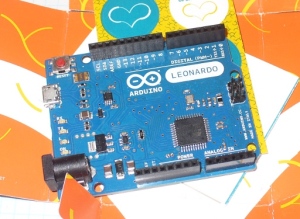
Here it is unwrapped from the cardboard packet:

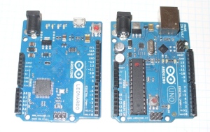
It uses the same physical footprint as the Uno, so no surprises there:

 Now to travel around the board and see what’s new. First is the microcontroller – we have the Atmel ATmega32U4:

There are several pros and cons to using the 32U4. The pros include:

  • More analogue inputs. As well as the usual A0~A5, digital pins 4,6,8,9,10 and 12 can be configured as A6~A11
  • It handles USB. So no more external USB controller MCU or the old FTDI chip. Supposedly this saves money, however the retail price in some markets don’t reflect this
  • More PWM pins – well one more. They’re now on D3, 5, 6, 9, 10, 11 and 13
  • There is a little more SRAM than the Uno, it is now 2.5 kB
  • SPI has moved – they’re now wired to the ICSP pins. So you now have D10~D13 seperate to SPI
And the cons:
  • SPI has moved – they’re now wired to the ICSP pins. So if you have any shields that use SPI – too bad, they’re out. The most common example of this will be Ethernet shields – you’ll need to modify them with some jumper leads to contact the ICSP pins
  • I2C has moved over to D2+3. So if you have any shields using I2C – they’ll need to be modified
  • Less flash memory – the bootloader uses 4 kB of the 32 kB flash (the Uno used 0.5 kB)

However you can get an adaptor shield to use older Arduino shields with the Leonardo.

For MCU to Arduino pin mapping, see here. Next, for more on the USB side of things – as the 32U4 takes care of USB – take heed of the following notes from arduino.cc:

Since the Leonardo does not have a dedicated chip to handle serial communication, it means that the serial port is virtual– it’s a software routine, both on your operating system, and on the Leonardo itself. Just as your computer creates an instance of the serial port driver when you plug in any Arduino, the Leonardo creates a serial instance whenever it runs its bootloader. The Leonardo is an instance of USB’s Connected Device Class (CDC) driver.

This means that every time you reset the board, the Leonardo’s USB serial connection will be broken and re-established. The Leonardo will disappear from the list of serial ports, and the list will re-enumerate. Any program that has an open serial connection to the Leonardo will lose its connection. This is in contrast to the Arduino Uno, with which you can reset the main processor (the ATmega328P) without closing the USB connection (which is maintained by the secondaryATmega8U2 or ATmega16U2 processor).

There are some other changes to the board. Moving on, the next change is the USB socket. Do you recognise this socket?

Yes – micro USB. Thankfully (!) a growing number of mobile phones use this type for charging and USB connection, so you may already have a matching cable. Note that the Leonardo doesn’t include a cable, so if you’re an iPhone user – order yourself a cable with your Leonardo.

Next, the LEDs have been moved to the edge of the board. You can see them in the above image to the right of the USB socket. No more squinting through shields at strange angles to check the TX/RX lights. However this isn’t a new invention, our friends at Freetronics have been doing this for some time. Furthermore, the reset button has been moved to the corner for easier access.

There are also seperate connectors for the I2C bus – next to AREF, which should make modifying existing shields a little easier:

 Finally, due to the reduction in components and shift to SMD – there is what could almost be called a large waste of space on the board:

A few extra user LEDs wouldn’t have been a bad idea, or perhaps circuitry to support Li-Po rechargeable batteries. However the argument will be “that’s what a protoshield is for”. Just saying… As for the rest of the hardware, the specifications can be found here.

Finally, the Leonardo is available in two versions – with and without headers. This makes it easier to embed the Leonardo into fixed applications as you can directly solder to the various I/O pins. An alternative to this would instead be the Freetronics LeoStick, as it is much smaller yet fully compatible.

Software

First – you need to drag yourself into Arduino IDE v1.0.1. Note you can run more than one version of the IDE on the same machine if you don’t mind sharing the same preferences file. Next, the Leonardo doesn’t reset when you open the serial monitor window (from arduino.cc) -

That means you won’t see serial data that’s already been sent to the computer by the board, including, for example, most data sent in the setup() function. This change means that if you’re using any Serial print(), println() or write() statments in your setup, they won’t show up when you open the serial monitor. To work around this, you can check to see if the serial port is open like so:

 // while the serial stream is not open, do nothing:
   while (!Serial) ;

Using the 32U4, you also have two serial ports. The first is the emulated one via the USB, and the second is the hardware UART on digital pins 0 and 1. Furthermore, the Leonardo can emulate a USB keyboard and mouse – however with a few caveats. There is a section on the Leonardo homepage that you should really read and take note of. But this emulation does sound interesting, and we look forward to developing some interesting tools to take use of them, so stay tuned.

Conclusion

There is nothing wrong with the Leonardo board, it works as described. However you could consider this a virtual “line in the sand”, or a new beginning. Due to the changes in the pinouts shields will need to be redesigned, and for those of you still programming in Arduino v23 – it’s time to get up to speed with v1.0.1. If you need the special USB functions, keyboard and/or mouse emulation, or are happy with the changes and can get one for less than the cost of a Uno – great.

Here’s a video from the main man Massimo Banzi:

However if you’re looking for your first Arduino board – this isn’t the board for you right now. There are too many incompatible shields out there, and the inability to cheaply replace the microcontroller will see some beginners burn out their first couple of boards rendering them useless. Get yourself an Arduino Uno or compatible board such as the Freetronics Eleven.

In conclusion, classifying the Leonardo board as good or bad is not a simple decision. It may or may not be an improvement – depending on your needs. Right now – for beginners, this is not the board for you. For those who understand the differences between a Uno and Leonardo, sure – no problem. Frankly, I would get a LeoStick instead.  At the end – it’s up to you to make an informed decision.

If you have any comments, leave them below. Thanks to Little Bird Electronics for the use of the Arduino Leonardo board.

In the meanwhile have fun and keep checking into tronixstuff.com. Why not follow things on twitterGoogle+, subscribe  for email updates or RSS using the links on the right-hand column? And join our friendly Google Group – dedicated to the projects and related items on this website. Sign up – it’s free, helpful to each other –  and we can all learn something.
Introduction

Recently the Arduino Leonardo was released, and I’ve finally got my hands on one. Some have claimed that the Leonardo as the successor to the Arduino Uno board, however that is somewhat subjective.  In this article we have a look for ourselves and examine the differences between the Uno boards that we’re used to and the new Leonardo.

The board

Here it is unwrapped from the cardboard packet:

It uses the same physical footprint as the Uno, so no surprises there:

 Now to travel around the board and see what’s new. First is the microcontroller – we have the Atmel ATmega32U4:

There are several pros and cons to using the 32U4. The pros include:

  • More analogue inputs. As well as the usual A0~A5, digital pins 4,6,8,9,10 and 12 can be configured as A6~A11
  • It handles USB. So no more external USB controller MCU or the old FTDI chip. Supposedly this saves money, however the retail price in some markets don’t reflect this
  • More PWM pins – well one more. They’re now on D3, 5, 6, 9, 10, 11 and 13
  • There is a little more SRAM than the Uno, it is now 2.5 kB
  • SPI has moved – they’re now wired to the ICSP pins. So you now have D10~D13 seperate to SPI
And the cons:
  • SPI has moved – they’re now wired to the ICSP pins. So if you have any shields that use SPI – too bad, they’re out. The most common example of this will be Ethernet shields – you’ll need to modify them with some jumper leads to contact the ICSP pins
  • I2C has moved over to D2+3. So if you have any shields using I2C – they’ll need to be modified
  • Less flash memory – the bootloader uses 4 kB of the 32 kB flash (the Uno used 0.5 kB)

However you can get an adaptor shield to use older Arduino shields with the Leonardo.

For MCU to Arduino pin mapping, see here. Next, for more on the USB side of things – as the 32U4 takes care of USB – take heed of the following notes from arduino.cc:

Since the Leonardo does not have a dedicated chip to handle serial communication, it means that the serial port is virtual– it’s a software routine, both on your operating system, and on the Leonardo itself. Just as your computer creates an instance of the serial port driver when you plug in any Arduino, the Leonardo creates a serial instance whenever it runs its bootloader. The Leonardo is an instance of USB’s Connected Device Class (CDC) driver.

This means that every time you reset the board, the Leonardo’s USB serial connection will be broken and re-established. The Leonardo will disappear from the list of serial ports, and the list will re-enumerate. Any program that has an open serial connection to the Leonardo will lose its connection. This is in contrast to the Arduino Uno, with which you can reset the main processor (the ATmega328P) without closing the USB connection (which is maintained by the secondaryATmega8U2 or ATmega16U2 processor).

There are some other changes to the board. Moving on, the next change is the USB socket. Do you recognise this socket?

Yes – micro USB. Thankfully (!) a growing number of mobile phones use this type for charging and USB connection, so you may already have a matching cable. Note that the Leonardo doesn’t include a cable, so if you’re an iPhone user – order yourself a cable with your Leonardo.

Next, the LEDs have been moved to the edge of the board. You can see them in the above image to the right of the USB socket. No more squinting through shields at strange angles to check the TX/RX lights. However this isn’t a new invention, our friends at Freetronics have been doing this for some time. Furthermore, the reset button has been moved to the corner for easier access.

There are also seperate connectors for the I2C bus – next to AREF, which should make modifying existing shields a little easier:

 Finally, due to the reduction in components and shift to SMD – there is what could almost be called a large waste of space on the board:

A few extra user LEDs wouldn’t have been a bad idea, or perhaps circuitry to support Li-Po rechargeable batteries. However the argument will be “that’s what a protoshield is for”. Just saying… As for the rest of the hardware, the specifications can be found here.

Finally, the Leonardo is available in two versions – with and without headers. This makes it easier to embed the Leonardo into fixed applications as you can directly solder to the various I/O pins. An alternative to this would instead be the Freetronics LeoStick, as it is much smaller yet fully compatible.

Software

First – you need to drag yourself into Arduino IDE v1.0.1. Note you can run more than one version of the IDE on the same machine if you don’t mind sharing the same preferences file. Next, the Leonardo doesn’t reset when you open the serial monitor window (from arduino.cc) -

That means you won’t see serial data that’s already been sent to the computer by the board, including, for example, most data sent in the setup() function. This change means that if you’re using any Serial print(), println() or write() statments in your setup, they won’t show up when you open the serial monitor. To work around this, you can check to see if the serial port is open like so:

// while the serial stream is not open, do nothing:
while (!Serial) ;

Using the 32U4, you also have two serial ports. The first is the emulated one via the USB, and the second is the hardware UART on digital pins 0 and 1. Furthermore, the Leonardo can emulate a USB keyboard and mouse – however with a few caveats. There is a section on the Leonardo homepage that you should really read and take note of. But this emulation does sound interesting, and we look forward to developing some interesting tools to take use of them, so stay tuned.

Conclusion

There is nothing wrong with the Leonardo board, it works as described. However you could consider this a virtual “line in the sand”, or a new beginning. Due to the changes in the pinouts shields will need to be redesigned, and for those of you still programming in Arduino v23 – it’s time to get up to speed with v1.0.1. If you need the special USB functions, keyboard and/or mouse emulation, or are happy with the changes and can get one for less than the cost of a Uno – great.

Here’s a video from the main man Massimo Banzi:

However if you’re looking for your first Arduino board – this isn’t the board for you right now. There are too many incompatible shields out there, and the inability to cheaply replace the microcontroller will see some beginners burn out their first couple of boards rendering them useless. Get yourself an Arduino Uno or compatible board such as the Freetronics Eleven.

In conclusion, classifying the Leonardo board as good or bad is not a simple decision. It may or may not be an improvement – depending on your needs. Right now – for beginners, this is not the board for you. For those who understand the differences between a Uno and Leonardo, sure – no problem. Frankly, I would get a LeoStick instead.  At the end – it’s up to you to make an informed decision.

In the meanwhile have fun and keep checking into tronixstuff.com. Why not follow things on twitterGoogle+, subscribe  for email updates or RSS using the links on the right-hand column? And join our friendly Google Group – dedicated to the projects and related items on this website. Sign up – it’s free, helpful to each other –  and we can all learn something.
The post First Look – the Arduino Leonardo appeared first on tronixstuff.

May
21

USB-Rubber Ducky scripts on Arduino/Leostick

arduino, General, LeoStick Comments Off on USB-Rubber Ducky scripts on Arduino/Leostick 

The other day I was at Jaycar and saw that they are now selling small USB sticks that are arduino compatible.
It is called the LeoStick and is made by Freetronics down in Melbourne.
Seeing that it could pretend to be a USB HID device (ie keyboard/mouse) I wondered if I could do the sort of thing that the USB Rubber Ducky from Hak5 can do
As it turns out the answer is YES :)

Since it was possible I spent an hour or two writing a quick shell script which can convert ducky script payloads into a sketch suitable for uploading to the LeoStick (or any arduino that has USB-HID capability)   The end result is a small bash script which can be downloaded from compile_payload.sh

Usage is fairly simple – you run the script with two options – the first being the payload file, and the second being the arduino script output.

ie: compile_payload lock_prank.txt lock_prank.ino

Various payloads can be found linked from the USB-Rubber-Ducky wiki

As a bit of fun I changed the lock_prank payload to work on Gnome/Linux and it also plays the mission impossible theme once done ;)
Grab it from lock_prank.ino

Also note that to get this working you need to edit the arduino libraries so that the sendReport function is marked as public.

To to this edit the USBAPI.h file which can be found in ${ARDUINO_DIR}/hardware/arduino/cores/arduino directory.
This may be /usr/share/arduino/hardware/arduino/cores/arduino/USBAPI.h or similar
If you installed the LeoStick board stuff from their website then it will be under your sketches directory as hardware/LeoStick/cores/arduino/USBAPI.h

Open that file and find

private:
    KeyMap* _keyMap;
    void sendReport(KeyReport* keys);
    void setKeyMap(KeyMap* keyMap);
public:
    Keyboard_();
    virtual size_t write(uint8_t);

Then change that to

private:
    KeyMap* _keyMap;
    void setKeyMap(KeyMap* keyMap);
public:
    void sendReport(KeyReport* keys);
    Keyboard_();
    virtual size_t write(uint8_t);

Then everything should work fine.


  • Newsletter

    Sign up for the PlanetArduino Newsletter, which delivers the most popular articles via e-mail to your inbox every week. Just fill in the information below and submit.

  • Like Us on Facebook