Posts | Comments

Planet Arduino

Archive for the ‘Arduino Mega 2560’ Category

A small keyboard form factor retrocomputer with blue keys on a black background sits in front of a display and a LEGO model of the Space Shuttle. There are a number of jumper wires and a breadboard coming from an open panel on the right side of the machine.

In case you weren’t around in the 80s, or you happened to blink, you may have missed the Mattel Aquarius computer. [Nick Bild] has a soft spot in his heart for the machine though and built the Aqua cartridge to make the Aquarius into a more usable machine.

Originally equipped with a mere 4 KB of RAM and a small, rubbery keyboard, it’s not too surprising that the Aquarius only lasted five months on the market. [Nick] decided on the cartridge slot to beef up the specs of this little machine given the small number of expansion ports on the device. Adding 32 KB of RAM certainly gives it a boost, and he also designed an SD card interface called Aqua Write that connects to the Aqua cartridge for easily transferring files from a more modern machine.

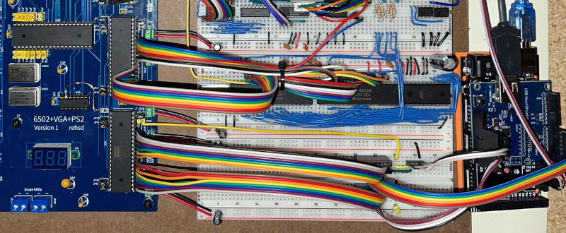
The Aqua Write uses an Arduino Mega 2560 to handle moving data between the SD card and the system’s memory. This is complicated somewhat because a “PLA sits between the Z80 and data bus that XORs data with a software lock code (initialized to a random value on startup).” [Nick] gets around this by running a small program to overwrite the lock code to zero after startup.

Getting data on and off retrocomputers can certainly be a challenge. If you’re trying to get files on or off another old machine, check out this Simple Universal Modem or consider Using a Raspberry Pi as a Virtual Floppy Drive.

Sketch of a Tandy TRS-80 Model 100 with Arduino Mega 2560

When [Stephen Cass] found himself with a broken Tandy TRS-80 Model 100 portable computer, the simplest solution was to buy another broken one and make one working computer from two non-working computers. However, this left him with a dilemma — what to do with the (now even more) broken one left over?

LCD layout is unusual by modern standard, but optimized for fast updates

Naturally, he did what a lot of us would do and used modern hardware to interface with the original parts that still work. In this case it meant replacing the motherboard with an Arduino Mega 2560.

Luckily, the Model 100 has a substantial fanbase and there’s a lot of helpful information available online, including the detailed service manual, that helped [Stephen] to understand how to drive the unusual display.  The LCD has a resolution of 240×64 pixels, which are broken down into eight zones of 50×32 pixels, and two zones of 40×42 pixels.  Each zone is then further divided into four banks, eight pixels tall, so that each column of eight pixels corresponds to a single byte.

Every one of the ten zones is controlled by an individual HD44102 driver IC, connected to a 30-bit wide bus for selecting the correct chip, bank and column.

With the Arduino handling the data, the old LCD still needed a -5 V supply for contrast and an RC filter to smooth out the PWM signal [Stephen] is using to adjust the viewing angle.

With the new interface, [Stephen] is able to access all of the pixels on the original display, and to use modern graphics libraries such as displayio. With the display issue solved, he intends to use a separate Teensy 4.1 to connect with the keyboard matrix and provide a VT100 terminal interface.

Schematic of the HD44102 driver circuit

Upcycling old, broken hardware can be a lot of fun and is always educational.  Understanding why certain design decisions were made at a time when the engineering trade-offs were different can lead to insights that are directly relevant to modern designs when resources get tight. In this case, the quirky LCD drivers were a response to making the display of text as efficient as possible, so as not to overburden the processor.

The TRS-80 computers are ripe for hacking, with their “built-for-service” designs, and we’ve featured a few in the past.  Some have replaced the motherboard with something newer, like [Stephen], whereas others have also replaced the display, or connected them to the cellphone network.

Have you found new ways to get old hardware working? Tell us in the comments below or send us a message on the Hackaday tips line.

Thanks to [nb0x0308] for the tip!

In the Northern hemisphere, summer is about to hit us full bore. While we love the season, we do dislike lawn maintenance. Apparently, so does [salmec] who developed the Mowerino around an Arduino Mega 2560 board.

As you might expect, the robot uses sharp blades so, you probably want to be careful. There are sensors that allow the machine to self-navigate or you can control it via Bluetooth. This is one of those things that seems easy until you try to actually do it. Nylon trimmer string is probably safer, but it breaks and it is hard to keep it cutting. Blades are more robust but also riskier to things like rocks, fingers, and pets.

Moving around in the yard is also an issue. The Mowerino has some ordinary-looking caster wheels in the front. That might be a place for improvement since most yards are not friendly to that kind of wheel. The other thing we worried about is what happens to the grass clippings. Around here, a week of rain means your mower will choke on grass clippings. On the other hand, the Mowerino has a smaller blade so maybe that helps mitigate clipping clogging.

Overall, though, it looks like it might be a good place to start if you dream of robot groundskeepers patrolling your estate. Most of the mowers we see like this have big wheels. But, of course, not all of them.

When building your own homebrew computer, everything is a challenge. Ultimately, that’s kind of the point. If you didn’t want to really get your hands dirty with the nuts and bolts of the thing, you wouldn’t have built it in the first place. For example, take the lengths to which [rehsd] was willing to go in order to support standard USB mice on their 6502 machine.

Code for mapping mouse movement to digital output.

The idea early on was to leverage existing Arduino libraries to connect with a standard USB mouse, specifically, the hardware would take the form of an Arduino Mega 2560 with a USB Host Shield. There was plenty of code and examples that showed how you could read the mouse position and clicks from the Arduino, but [rehsd] still had to figure out a way to get that information into the 6502.

In the end, [rehsd] connected one of the digital pins from the Arduino to an interrupt pin on the computer’s W65C22 versatile interface adapter (VIA). Then eleven more digital pins were connected to the computer, each one representing a state for the mouse and buttons, such as MOUSE_CLICK_RIGHT and MOUSE_LEFT_DOWN.

Admittedly, [rehsd] says the mouse action is far from perfect. But as you can see in the video after the break, it’s at least functional. While the code could likely be tightened up, there’s obviously some improvements to be made in terms of the electrical interface. The use of shift registers could reduce the number of wires between the Arduino and VIA, which would be a start. It’s also possible a chip like the CH375 could be used, taking the microcontroller out of the equation entirely.

From classic breadboard builds to some impressively practical portable machines, we’ve seen our fair share of 6502 computers over the years. Despite the incredible variation to be found in these homebrew systems, one thing is always the same: they’re built by some of the most passionate folks out there.

[Thanks to Jim for the tip.]

Considering the state of well, everything, we can’t tell you how glad we are to be out of school. That goes double for not being a teacher these days. [Elena] had some awesome light-up tactile buttons set aside for a killer Kerbal Space Program controller, but it’s funny how a pandemic will change your priorities. Instead, those buttons found a good home in this colorful and enticing Zoom control panel.

[Elena]’s ready pile of Arduinos yielded no Leonardos or Pro Micros, but that’s okay because there’s a handy bootloader out there that allows you to reprogram the USB interface chip of an Uno or a Mega and use it as a keyboard. After setting that up, it was mostly a matter of wiring all those latching and momentary buttons and LEDs to the Mega and making them look fantastic with a set of icons. (We all know the big red mushroom button is for aborting the call; so does it really need an icon?)

[Elena] was inspired by the Zoom call-terminating pull chain we saw a month or so ago as well as the pink control box that launched a thousand or so macro keyboards. Have you made your own sanity-saving solution for our times? Let us know!

It’s a common enough situation, that when an older piece of equipment dies, and nobody wants to spend the money to repair it. Why fix the old one, when the newer version with all the latest bells and whistles isn’t much more expensive? We all understand the decision from a business standpoint, but as hackers, it always feels a bit wrong.

Which is exactly why [tommycoolman] decided to rebuild the office’s recently deceased Duplo CC-330 heavy duty business card cutter. It sounds like nobody really knows what happened to the machine in the first place, but since the majority of the internals were cooked, some kind of power surge seems likely. Whatever the reason, almost none of the original electronics were reused. From the buttons on the front panel to the motor drivers, everything has been implemented from scratch.

An Arduino Mega 2560 clone is used to control four TB6600 stepper motor drivers, with a common OLED display module installed where the original display went. The keypad next to the screen has been replaced with 10 arcade-style buttons soldered to a scrap of perfboard, though in the end [tommycoolman] covers them with a very professional looking printed vinyl sheet. There’s also a 24 V power supply onboard, with the expected assortment of step up and step down converters necessary to feed the various electronics their intended voltages.

In the end, [tommycoolman] estimates it took about $200 and 30 hours of work to get the card cutter up and running again. The argument could be made that the value of his time needs to be factored into the repair bill as well, but even still, it sounds like a bargain to us; these machines have a four-figure price tag on them when new.

Stories like this one are important reminders of the all wondrous things you can find hiding in the trash. Any time a machine like this can be rescued from the junkyard, it’s an accomplishment worthy of praise in our book.

The Z80 is one of those old CPUs that is both obtainable and easy to work with — at least in some versions. [Doctor Volt] put together what may be the simplest possible setups to get a working Z80 system. He has the processor, of course. But everything else — clock, memory, and power — are from an Arduino Mega 2560. You could argue that’s two chips, but the board actually has several chips on it. On the other hand, you could probably pull off the same stunt with a bare ATMega 2560.

We’ve seen this done before, but usually with a few more support chips. If you are a purist, [Doctor Volt] also has some Z80 and CP/M experiments where the Arduino only acts as a disk drive for the computer and there are only two support chips. There are three videos for both projects that you can see below.

We were struck by how simple the first project was, though. Around 100 lines of source code is all it takes, and some of those are comments. The Arduino even provides the system memory (1K of it) and you initialize it by changing the memory.h file and reloading the Arduino.

The code does a bit of setup for interrupts and the clock and then just spins. The Arduino gets an interrupt on a CPU read and a different interrupt on a CPU write. All memory reads draw out of the simulated 1K RAM and memory writes go there, as well. The write code also can detect an I/O port write and sends that data to the Arduino serial port. It doesn’t appear to matter what I/O port you write to.

This reminded us of one of our favorite cheap Z80 projects. That board uses an ATMega32A in a similar way but also has external RAM. If you add a few EEPROMs to act as disk drives, it sits somewhere in the middle of the two computers from [Doctor Volt]. With so few parts, it is easy to get these 8-bit wonders in fairly small spaces.

Today’s commercial aircraft are packed to the elevators with sensors, computers, and miles and miles of wiring. Inside the cockpit you’re more than likely to see banks of LCDs and push buttons than analog gauges. So what’s that mean for the intrepid home simulator builder? Modern problems require modern solutions, and this 3D printed simulator is about as modern as it gets.

Published to Thingiverse by the aptly named [FlightSimMaker], this project consists of a dizzying number of 3D-printed components that combine into a full-featured desktop simulator for the Garmin G1000 avionics system. Everything from the parking brake lever to the push buttons in the display bezels was designed and printed: over 200 individual parts in all. Everything in this X-Plane 11 compatible simulator is controlled by an Arduino Mega 2560 with the SimVim firmware.

To help with connecting dozens of buttons, toggle switches, and rotary encoders to the Arduino, [FlightSimMaker] uses five CD74HC4067 16-channel multiplexers. The display is a 12.1 inch 1024 x 768 LCD panel with integrated driver, and comes in at the second most expensive part of the build behind the rotary encoders. All told, the estimated cost per display is around $250 USD.

Even if you aren’t looking to build yourself a high-tech flight simulator, there’s plenty of ideas and tips here that could be useful for building front panels. We particularly like the technique used for doing 3D-printed lettering: the part is printed in white, spray painted a darker color, and then the paint is sanded off the faces of the letters to reveal the plastic. Even with a standard 0.4 mm nozzle, this results in clean high-contrast labels on the panel with minimal fuss.

Of course, while impressive, these panels are just the beginning. There’s still plenty more work to do if you want to build an immersive simulation experience. Including, in the most extreme cases, buying a Boeing 737 cockpit.

There’s no question that you can get a lot done with the classic multimeter; it’s arguably the single most capable tool on your bench. But the farther down the rabbit hole of hacking and reverse engineering you go, the more extravagant your testing and diagnostic gear tends to get. For some of us that’s just an annoying reality of the game. For others it’s an excuse to buy, and maybe even build, some highly specialized equipment. We’ll give you one guess as to which group we fall into here at Hackaday.

[Akshay Baweja] is clearly a member of the second group. He’s recently published a guide on building a very slick intelligent Integrated Circuit tester with a total cost of under $25 USD. Whether you’re trying to identify an unknown chip or verifying your latest parts off the slow-boat from China actually work before installing them in your finished product, this $25 tool could end up saving you a lot of time and aggravation.

[Akshay] walks readers through the components and assembly of his IC tester, which takes the form of a Shield for the Arduino Mega 2560. The custom PCB he designed and had manufactured holds the 20 Pin ZIF Socket as well as the 2.4 inch TFT touch screen. The screen features an integrated micro SD slot which is important as you need the SD card to hold the chip database.

With an IC to test inserted into the ZIF socket, the user can have the tester attempt to automatically ID the chip or can manually enter in a part number to lookup. The source code for the Arduino as well as the chip ID database is up on GitHub for anyone looking to add some more hardware to the device’s testing repertoire.

The importance of good test equipment simply cannot be overstated. Between highly specialized gear like this IC tester to classic instruments such as the oscilloscope, your bench is going to be full of weird and wonderful pieces of equipment before too long.

Certamen is a special class of  high school quiz bowl tournament that’s focused solely on the classics. No, not Austen and Dickens, the actual classics. All the questions are about stuff like ancient Greek and Roman civilization and culture, classical mythology, and the finer points of Latin grammar. Like any other quiz bowl, the contestants use buttons to buzz in and answer the questions.

To win at Certamen, a team needs more than just a vast working knowledge of classical antiquity. They also have to be fast on the buzzer. The best way to do that is to practice with official equipment. But this is Hackaday, so you know what comes next: all the ones you can buy cost five times more than they should, so [arpruss] made an awesome open-source version for a fraction of the cost.

The practice machine consists of 12 arcade-style buttons connected to a control box. An Arduino Mega in the control box records the order of button presses as they arrive and displays a corresponding code on an LCD. A toggle switch selects between Certamen mode, where one button press locks out the rest of the team, and a Quiz mode with no lockout.

Our favorite thing about this build is the way [arpruss] took care of managing long cables, which was one of his main must-haves. The buttons are wired to the control box with Cat6 in three groups of four—one cable per table, one pair per chair. Our other favorite thing is the Easter eggs. Hold down the clear button on the control box when the system is booting and one of two things happens: either the buttons band together and turn into piano keys, or some Latin poetry appears on the screen.

[arpruss]’s 3D-printed buzzer bases look pretty slick. If Certamen practice ever starts to get out of hand, he might consider more robust packaging, like these Devo hat buttons.


Filed under: Arduino Hacks, classic hacks


  • Newsletter

    Sign up for the PlanetArduino Newsletter, which delivers the most popular articles via e-mail to your inbox every week. Just fill in the information below and submit.

  • Like Us on Facebook