After many years working with and teaching others about the Arduino development platform, it became apparent that there needed to be a useful guide to get people started in the world of AVR microcontrollers – used in Arduino and other development environments. The great people at No Starch Press agreed and we are now proud to have published “AVR Workshop – A Hands-On Introduction with 60 Projects“.
AVR Workshop is written for several groups of people:
Those of you who have used an Arduino but now want to learn how to harness the underlying AVR microcontrollers without the layer of Arduino abstraction.
Anyone interested in electronics and wanting to start with using microcontrollers.
Students who are going to learn how to use AVR microcontrollers in their coursework.
People tasked with making devices based around 8-bit AVR microcontrollers and don’t know where to start
AVR users who would like a neat reference on using popular devices with their microcontrollers and don’t have all day to scour the Internet for tested, quality resources.
You. Yes, you. Learning is for a lifetime, so why not get started with the world of electronics and microcontrollers? Or give a copy to someone who enjoys learning about technology?
Anyone can use this book. You don’t need any previous experience in electronics, programming, or making things. AVR Workshop will take you step-by-step from the beginning including installation of the required software, explain electronics when required, teach you the required coding and walk you through examples including sixty projects enabling you to harness popular 8-bit Microchip AVR microcontrollers.
Once you’ve worked through the book – you will have the knowledge, experience and confidence to branch out on your own and build complex projects, work with other Microchip AVR microcontrollers – and find success in this fascinating field. You will also have a useful reference tool that you can refer to when making your own devices.
Unlike other books or resources found online, I don’t hide any details from you in order to simplify things. Important functions aren’t hidden away in software libraries – instead you’ll learn how to control the microcontroller down to the register level to control all sorts of useful devices. Instead of relying on others – you’ll learn how to write your own libraries, so you can make your own parts and devices easier to work with.
You don’t need to spend a fortune, in fact I’ve written AVR Workshop to be as economical as possible for you, the reader. The required software is small, free to download and can operate on Linux, MacOS or Windows using machines that date back almost ten years. You don’t need any cloud-based tools or the latest i7 or M2-based computer… almost any will do.
AVR Workshop is printed using a convenient lie-flat technology, so you can have the book open to your side and not worry about the pages flapping about and losing your position while working on your projects. All the required code is included in the book, however you can also download them along with a list of parts and supplier information from the book’s website.
The Microchip AVR series of 8-bit microcontrollers are, in my opinion, an inexpensive and most approachable way of learning about electronics and microcontrollers – and open up a whole new world of creativity or even the pathway to a career in technology. A copy of AVR Workshop is the best guide to start anyone in this world.
To learn more about AVR Workshop, you can review the table of contents, download a sample chapter, code and parts list and order copies for yourself and others from the No Starch Press online store. Orders from No Starch Press also include a free electronic copy so you can get started immediately.
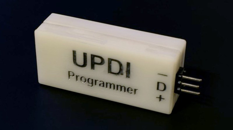
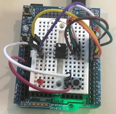
[Daumemo] likes experimenting with DIY electronics, and like many people, eventually ran across an AVR microcontroller with a Unified Program and Debug Interface (UPDI). One option is of course to purchase an UPDI programmer, but an even better solution was to make a DIY USB version from nice, cheap parts.
Programming an Attiny404 over the UPDI interface.
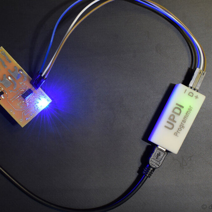
UPDI is an interface for external programming and on-chip debugging of microcontrollers, and [Daumemo]’s solution is based on the jtag2updi project. It combines an Arduino Nano (in this case, a clone) with a single resistor, a single capacitor, and a six pin angled header (with a cleverly bent pin) to enable programming UPDI devices over a USB connection. [Daumemo] is happy to report that the device works just fine in both Microchip Studio with AVRDUDE, or PlatformIO.
Is an Arduino Nano a bit overpowered in this role? Maybe, but the price is certainly right. There’s no need for a custom PCB either, since everything can be soldered direct to the Nano board. A matching 3D printed enclosure is about all that’s needed to make a robust and reliable DIY USB UPDI programmer out of a handful of parts, and that sounds good to us.
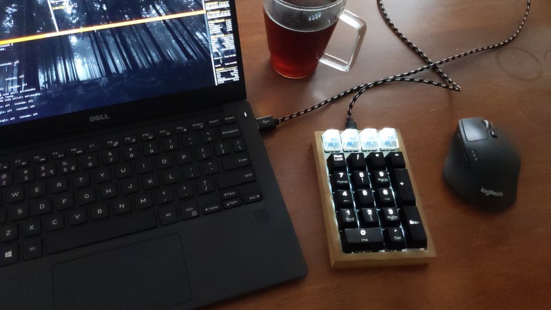
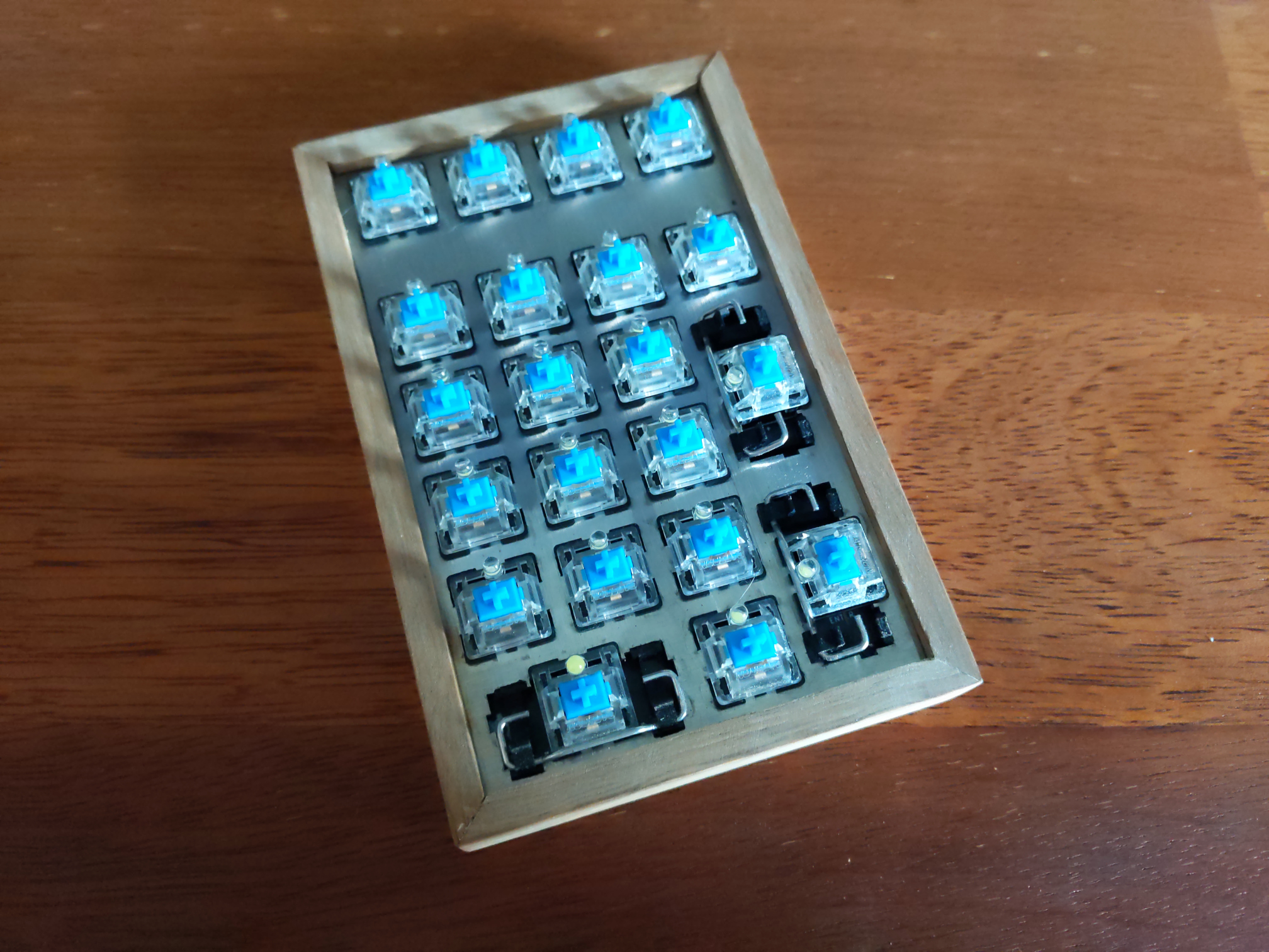
Why buy a num pad or a macropad when you can build something new and beautiful, open source that bad boy, and be a hero to the community? We think that should be all the justification you ever need to build instead of buy, even if you think your thing is Just Another Keypad [JAnK] as [Clewsy] claims.
At first glance, JAnK appears to be a standard number pad with four macro keys across the top. But when you roll your own ‘board, all the keys are programmable. [Clewsy] took advantage of this by adding a second layer that’s accessible with (what else?) the Num Lock key. This switches JAnK over to 21-key macro pad mode.
[Clewsy] rolled their own PCB for this and used the venerable ATMega32u4 because of its HID and USB host capabilities. Every key is backlit, and these LEDs are driven by an MP3202 LED driver and PWM from the AVR. [Clewsy] was able to build a prototype by sawing the num pad off of a stainless steel key switch plate from another build, but eventually ordered JAnK its own custom, laser-cut, stainless steel plate. The lovely enclosure is made of spotted gum wood and an acrylic base.
Putting it all together proved to be a bit problematic. [Clewsy] soldered up the minimum viable components for testing and discovered that the ATMega’s VCC and GND pins were both shorted. This killed the AVR programmer, but not the chip itself, and [Clewsy] happened to have a spare. To add insult to injury, the Num Lock light didn’t work, but [Clewsy] was able to simply reverse the LED instead of ordering a new pile of boards. Check out the detailed write-up with code and tons of pictures over on [Clewsy]’s personal site.
There’s a school of thought that says that to fully understand something, you need to build it yourself. OK, we’re not sure it’s really a school of thought, but that describes a heck of a lot of projects around these parts.
[Tim] aka [mitxela] wrote kiloboot partly because he wanted an Ethernet-capable Trivial File Transfer Protocol (TFTP) bootloader for an ATMega-powered project, and partly because he wanted to understand the Internet. See, if you’re writing a bootloader, you’ve got a limited amount of space and no device drivers or libraries of any kind to fall back on, so you’re going to learn your topic of choice the hard way.
[Tim]’s writeup of the odyssey of cramming so much into 1,000 bytes of code is fantastic. While explaining the Internet takes significantly more space than the Ethernet-capable bootloader itself, we’d wager that you’ll enjoy the compressed overview of UDP, IP, TFTP, and AVR bootloader wizardry as much as we did. And yes, at the end of the day, you’ve also got an Internet-flashable Arduino, which is just what the doctor ordered if you’re building a simple wired IoT device and you get tired of running down to the basement to upload new firmware.
Oh, and in case you hadn’t noticed, cramming an Ethernet bootloader into 1 kB is amazing. If doing big things in small codespaces floats your boat, check out the winners from our own 1kB challenge.
Speaking of bootloaders, if you’re building an I2C slave device out of an ATtiny85¸ you’ll want to check out this bootloader that runs on the tiny chip.
I’ve always appreciated simulation tools. Sure, there’s no substitute for actually building a circuit but it sure is handy if you can fix a lot of easy problems before you start soldering and making PCBs. I’ve done quite a few posts on LTSpice and I’m also a big fan of the Falstad simulator in the browser. However, both of those don’t do a lot for you if a microcontroller is a major part of your design. I recently found an open source project called Simulide that has a few issues but does a credible job of mixed simulation. It allows you to simulate analog circuits, LCDs, stepper and servo motors and can include programmable PIC or AVR (including Arduino) processors in your simulation.
The software is available for Windows or Linux and the AVR/Arduino emulation is built in. For the PIC on Linux, you need an external software simulator that you can easily install. This is provided with the Windows version. You can see one of several videos available about an older release of the tool below. There is also a window that can compile your Arduino code and even debug it, although that almost always crashed for me after a few minutes of working. As you can see in the image above, though, it is capable of running some pretty serious Arduino code as long as you aren’t debugging.
Looks and sounds exciting, right? It is, but be sure to save often. Under Linux, it seems to crash pretty frequently even if you aren’t debugging. It also suffers from other minor issues like sometimes forgetting how to move components. Saving, closing the application, and reopening it seems to fix that. Plus, we assume they will squash bugs as they are reported. One of my major hangs was solved by removing the default (old) Arduino IDE and making sure the most recent was on the path. But the crashing was frequent and seemed more or less random. It seemed that I most often had crashes on Linux with occasional freezes but on Windows it would freeze but not totally crash.
Basic Operation
The basic operation is pretty much what you’d expect. The window is broadly divided into three panes. The leftmost pane shows, by default, a palette of components. You can use the vertical tab strip on the left to also pick a memory viewer, a property inspector, or a file explorer.
The central pane is where you can draw your circuit and it looks like a yellow piece of engineering paper with a grid. Along the top are file buttons that do things like save and load files.
You’ll see a similar row of buttons above the rightmost pane. This is a code editor and debugging window that can interface with the Arduino IDE. It looks like it can also interface with GCBasic for the PIC, although I didn’t try that.
You drag components from the left onto the circuit. Wiring isn’t a distinct operation. You just let the mouse float over the connection until the cursor makes a cross. Click and then drag to the connection point and click again. Sometimes the program forgets to make the cross cursor and then I’ve had to save and restart.
Most of the components are just what you think they are. There are some fun ones including a keypad, an LED matrix, text and graphic LCDs, and even stepper and servo motors. You’ll also find several logic functions, 7400-series ICs, and there are annotation tools like text and boxes at the very bottom. You can right click on a category and hide components you never want to see.
At the top, you can add a voltmeter, an ammeter, or an oscilloscope to your circuit. The oscilloscope isn’t that useful because it is small. What you really want to do is use a probe. This just shows the voltage at some point but you can right click on it and add the probe to the plotter which appears at the bottom of the screen. This is a much more useful scope option.
There are a few quirks with the components. The voltage source has a push button that defaults to off. You have to remember to turn it on or things won’t work well. The potentiometers were particularly frustrating. The videos of older versions show a nice little potentiometer knob and that appears on my Windows laptop, too. On Linux the potentiometer (and the oscilloscope controls) look like a little tiny joystick and it is very difficult to set a value. It is easier to right click and select properties and adjust the value there. Just note that the value won’t change until you leave the field.
Microcontroller Features
If that’s all there was to it, you’d be better off using any of a number of simulators that we’ve talked about before. But the big draw here is being able to plop a microcontroller down in your circuit. The system provides PIC and AVR CPUs that are supported by the simulator code it uses. There’s also four variants of Arduinos: the Uno, Nano, Duemilanove, and the Leonardo.
You can use the built-in Arduino IDE — just make sure you have the real Arduino software on your path and it is a recent version. Also, unlike the real IDE, it appears you must save your file before a download or debug will notice the changes. In other words, if you make a change and download, you’ll compile the code before the change if you didn’t save the file first. You don’t have to use the built-in IDE. You can simply right click on the processor and upload a hex file. Recent Arduino IDEs have an option to export a hex file, and that works with no problem.
When you have a CPU in your design, you can right click it and open a serial monitor port which shows virtual serial output at the bottom of the screen and lets you provide input.
The debugging mode is simple but works until it crashes. Even without debugging, there is an option to the left of the screen to watch memory locations and registers inside the CPU.
Overall, the Arduino simulation seemed to work quite well. Connecting to the Uno pins was a little challenging at certain scales and I accidentally wired to the wrong pin on more than one occasion. One thing I found odd is that you don’t need to wire the voltage to the Arduino. It is powered on even if you don’t connect it.
Besides the crashing, the other issue I had was with the simulation speed which was rather slow. There’s a meter at the top of the screen that shows how slow the simulation is compared to real-time and mine was very low (10% or so) most of the time. There is a help topic explaining that this depends if you have certain circuit elements and ways to improve the run time, but it wasn’t bad enough that I bothered to explore it.
My first thought was that it would be difficult to handle a circuit with multiple CPUs in it since the debugging and serial monitors are all set up for a single CPU. However, as the video below shows, you can run multiple instances of the program and connect them via a serial port connection. The only issue would be if you had a circuit where both CPUs were interfacing with interrelated circuitry (for example, an op amp summing two signals, one from each CPU).
A Simple Example
As an experiment, I created a simple circuit that uses an Uno. It generates two PWM signals, integrates them with an RC circuit and then either drives a load or drives a load through a bipolar emitter follower. A pot lets you set the PWM percentages which are compliments of each other (that is, when one is at 10% the other is at 90%). Here’s the circuit:
Along with the very simple code:
int v;

const int potpin=0;
const int led0=5;
const int led1=6;

void setup() {
Serial.begin(9600);
Serial.println("Here we go!");
}

void loop() {
int v=analogRead(potpin)/4;
Serial.println(v);
analogWrite(led0,v);
analogWrite(led1,255-v);
delay(250);
}
Note that if the PWM output driving the transistor drops below 0.7V or so, the transistor will shut off. I deliberately didn’t design around that because I wanted to see how the simulator would react. It correctly models this behavior.
There’s really no point to this other than I wanted something that would work out the analog circuit simulation as well as the Arduino. You can download all the files from GitHub, including the hex file if you want to skip the compile step.
If you use the built-in IDE on the right side of the screen, then things are very simple. You just download your code. If you build your own hex file, just right click on the Arduino and you’ll find an option to load a hex file. It appears to remember the hex file, so if you run a simulation again later, you don’t have to repeat that step unless you moved the hex file.
However, the IDE doesn’t remember settings for the plotter, the voltage switches, or the serial terminal. You’ll especially want to be sure the 5V power switch above the transistor is on or that part of the circuit won’t operate correctly. You can right click on the Arduino to open the serial monitor and right click on the probes to bring back the plotter pane.
The red power switch at the top of the window will start your simulation. The screenshots above show close-ups of the plot pane and serial monitor.
Lessons Learned
This could be a really great tool if it would not crash so much. In all fairness, that could have something to do with my PC, but I don’t think that fully accounts for all of them. However, the software is still in pretty early development, so perhaps it will get better. There are a lot of fit and finish problems, too. For example, on my large monitor, many of the fonts were too large for their containers, which isn’t all that unusual.
The user interface seemed a little clunky, especially when you had to manipulate potentiometers and switches. Also, remember you can’t right-click on the controls but must click on the underlying component. In other words, the pot looks like a knob on top of a resistor. Right clicks need to go on the resistor part, not the knob. I also was a little put off that you can’t enter multiplier suffixes directly in component values. That is, you can’t enter a resistor value as 1K. You can enter 1000 or you can enter 1 and then change the units in a separate field to Kohms. But that’s not a big deal. You can get used to all of that if it would quit crashing.
I really wanted the debugging feature to work. While you can debug directly with simuavr or other tools, you can’t easily simulate all your I/O devices like you can with this tool. I’m hoping that becomes more robust in the future. Under Linux it would work for a bit and crash. On Windows, I never got it to work.
As I always say, though, simulation is great, but the real world often leads to surprises that don’t show up in simulation. Still, a simulation can help you clear up a host of problems before you commit to heating up the soldering iron or pulling out the breadboard. Simuide has the potential to be a great tool for simulating the kind of designs we see most on Hackaday.
If you want to explore other simulation options, we’ve talked a lot about LTSpice, including our Circuit VR series. There’s also the excellent browser-based Falstad simulator.
As every Hackaday reader knows, and tells us at every opportunity in the comments, adding an Arduino to your project instantly makes it twice as cool. But what if, in the course of adding an Arduino to your project, you run into a problem and need to debug the code? What if you could use a second Arduino to debug the first? That would bring your project up to two Arduinos, instantly making it four times as awesome as before you started! Who could say no to such exponential gains?
Debugging an ATTiny85
Not [Wayne Holder], that’s for sure. He writes in to let us know about a project he’s been working on for a while that allows you to debug the execution of code on an Arduino with a second Arduino. In fact, the target chip could even be another AVR series microcontroller such as a the ATTiny85. With his software you can single-step through the code, view and modify values in memory, set breakpoints, and even disassemble the code. Not everything is working fully yet, but what he has so far is very impressive.
The trick is exploiting a feature known as “debugWIRE” that’s included in many AVR microcontrollers. Unfortunately documentation on this feature is hard to come by, but with some work [Wayne] has managed to figure out how most of it works and create an Arduino Sketch that lets the user interact with the target chip using a simple menu system over the serial monitor, similar to the Bus Pirate.
[Wayne] goes into plenty of detail on his site and in the video included after the break, showing many of the functions he’s got working so far in his software against an ATTiny85. If you spend a lot of time working on AVR projects, this looks like something you might want to keep installed on an Arduino in your tool bag for the future.
I am a crappy software coder when it comes down to it. I didn’t pay attention when everything went object oriented and my roots were always assembly language and Real Time Operating Systems (RTOS) anyways.
So it only natural that I would reach for a true In-Circuit-Emulator (ICE) to finish of my little OBDII bus to speed pulse generator widget. ICE is a hardware device used to debug embedded systems. It communicates with the microcontroller on your board, allowing you to view what is going on by pausing execution and inspecting or changing values in the hardware registers. If you want to be great at embedded development you need to be great at using in-circuit emulation.
Not only do I get to watch my mistakes in near real time, I get to make a video about it also.
Getting Data Out of a Vehicle
I’ve been working on a small board which will plug into my car and give direct access to speed reported on the Controller Area Network (CAN bus).
To back up a bit, my last video post was about my inane desire to make a small assembly that could plug into the OBDII port on my truck and create a series of pulses representing the speed of the vehicle for my GPS to function much more accurately. While there was a wire buried deep in the multiple bundles of wires connected to the vehicle’s Engine Control Module, I have decided for numerous reasons to create my own signal source.
At the heart of my project is the need to convert the OBDII port and the underlying CAN protocol to a simple variable representing the speed, and to then covert that value to a pulse stream where the frequency varied based on speed. The OBDII/CAN Protocol is handled by the STN1110 chip and converted to ASCII, and I am using an ATmega328 like found on a multitude of Arduino’ish boards for the ASCII to pulse conversion. I’m using hardware interrupts to control the signal output for rock-solid, jitter-free timing.
Walk through the process of using an In-Circuit Emulator in the video below, and join me after the break for a few more details on the process.
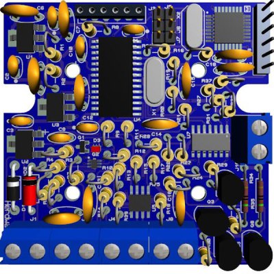
The Hardware
I revised the board since the last video and removed the support for the various protocols other than CAN, which is the non-obsolete protocol of the bunch. By removing a bunch of parts I was able to change the package style to through-hole which is easier for many home hobbyists, so you can leave the solder-paste in the ‘fridge.
The “Other Connector” on your Arduino
Unlike the Arduino which is ready to talk to your USB port when you take it out of the box, the ATmega chips arrive without any knowledge of how to go and download code, in other words it doesn’t have a boot loader. Consequently I have the In-Circuit-Serial-Programming (ICSP) pins routed to a pin header on my board so that I can program the part directly.
On this connector you’ll find the Reset line, which means with this header I can use a true ICE utilizing the debugWIRE protocol. Since the vast majority of designs that use an AVR chip do not repurpose the reset pin for GPIO, it is a perfect pin to use for ICE. All of the communications during the debug process will take place on the reset pin.
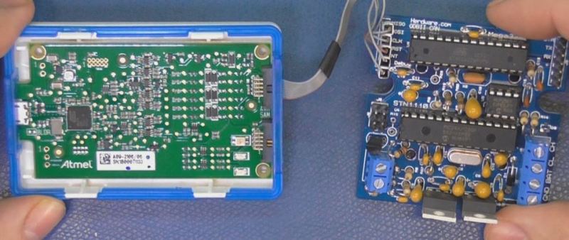
Enter the ICE
When designing a computer from scratch there is always the stage where nothing yet works. Simply put, a microprocessor circuit cannot work until almost every part of the design works; RAM, ROM, and the underlying buses all need to (mostly) work before simple things can be done. As a hardware engineer by trade I would always reach for an ICE to kick off the implementation; only after the Beta release would the ICE start to gather dust in the corner.
In the case of the ATmega, the debugging capabilities are built into the microcontroller itself. This is a much more straightforward implementation than the early days when we had to have a second isolated processor running off-board with its own local RAM/ROM.
One note mentioned in the video is that a standard Arduino’ish board needs to have the filter capacitors removed from the RESET line to allow the high speed data on the line for its debugWIRE usage.
The ICE I am using here is the one made by Atmel, and is compatible with Atmel Studio, there are also other models available such as the AVR Dragon.
ICEyness
The ICE allows us to download and single step our code while being able to observe and overwrite RAM and I/O Registers from the keyboard. We are able to watch the program step by step or look underneath at the actual assembly code generated by the compiler. We can watch variables and locations directly in RAM or watch the C language counterparts. It’s also possible to jump over a sub-routine call in the instance of just wanting to see the result without all of the processing.
This video was really about finishing the OBDII circuit so I didn’t really have the time to go over everything an ICE can do, maybe I will do a post dedicated to just the ICE and development environment next time.
We often see “logic analyzer” projects which are little more than microcontrollers reading data as fast as they can, sending it to a PC, and then plotting the results. Depending on how fast the microcontroller is, these projects range from adequate to not very useful.
At first glance, [esot.eric’s] logic analyzer project has an AVR in it, so it ought to be on the low end of the scale. Then you look at the specs: 32 channels at 30 megasamples per second. How does that work with an AVR in it?
The answer lies in the selection of components. The analyzer uses a 128MB SDRAM DIMM (like an older PC might use for main memory). That makes sense; the Arduino can’t store much data internally. However, it isn’t the storage capacity that makes this choice critical. It seems [esot.eric] has a way to make the RAM “free run”.
The idea is to use the Arduino (or other host microcontroller) to set up the memory. Some of the memory’s output bits feedback to the address and data lines. Then the microcontroller steps aside and the SDRAM clocks samples into its memory by itself at the prevailing clock rate for the memory.
Of course, this isn’t good for things like complex triggering, and you give up some memory storage to the control “program” (if that’s the right word). However, it is easy to see this technique being useful in other cases where you want to offload the CPU for repetitive data transfer. For example, [esot.eric] has also used this method to drive an LCD panel.
Just to prove the point, the video below shows the device working even after the AVR microcontroller is removed. It is only necessary during the setup phase. Admittedly, the logic analyzer part isn’t the cool part. If you want a logic analyzer, pick up a DSLogic from the Hackaday store or one of the many other inexpensive ones out there. If you want to roll your own, there are plenty of options for that, too.
But for sheer audacity and dirty trickery, you have to admire how this design uses an SDRAM in a unique way. It makes you wonder what other components we could use in strange ways.
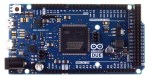
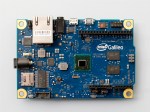
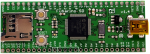
Speak with those who consider themselves hardcore engineers and you might hear “Arduinos are for noobs” or some other similar nonsense. These naysayers see the platform as a simplified, overpriced, and over-hyped tool that lets you blink a few LEDs or maybe even read a sensor or two. They might say that Arduino is great for high school projects and EE wannabes tinkering in their garage, but REAL engineering is done with ARM, x86 or PICs. Guess what? There are Arduino compatible boards built around all three of those architectures. Below you can see but three examples in the DUE, Galileo, and Fubarino SD boards.
This attitude towards Arduino exists mainly out of ignorance. So let’s break down a few myths and preconceived biases that might still be lurking amongst some EEs and then talk about Arduino’s ability to move past the makers.
Arduino is NOT the Uno
When some hear “Arduino”, they think of that little blue board that you can plug a 9v battery into and start making stuff. While this is technically true, there’s a lot more to it than that.
An Arduino Uno is justanAVR development board.AVRs are similar to PICs. When someones says “I used a PIC as the main processor”, does that mean they stuck the entire PIC development board into their project? Of course not. It’s the same with Arduino (in most cases), and design is done the same way as with any other microcontroller –
Use the development board to make, create and debug.
When ready, move the processor to your dedicated board.
What makes an Arduino an “Arduino” and not justan AVR but the bootloader. Thus:
An Atmega328P is an AVR processor.
An Atmega328P with the Arduino bootloader is an Arduino.
The bootloader allows you to program the AVR with the Arduino IDE. If you remove the bootloader from the AVR, you now have an AVR development board that can be programmed with AVR Studio using your preferred language.
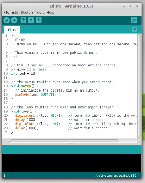
There Is No Special Arduino Language
Arduino “blink” sketch should run on any Arduino compatible board.
Yes, I know they call them sketches, which is silly. But the fact is it’s just c++. The same c++ you’d use to program your PIC. The bootloader allows the IDE to call functions, making it easy to code and giving Arduino its reputation of being easy to work with. But don’t let the “easy” fool you. They’re real c/c++ functions that get passed to a real c/c++ compiler. In fact, any c/c++ construct will work in the Arduino IDE. With that said – if there is any negative attribute to Arduino, it is the IDE. It’s simple and there is no debugger.
The strength comes in the standardization of the platform. You can adapt the Arduino standard to a board you have made and that adaptation should allow the myriad of libraries for Arduino to work with your new piece of hardware. This is a powerful benefit of the ecosystem. At the same time, this easy of getting things up and running has resulted in a lot of the negative associations discussed previously.
So there you have it. Arduino is no different from any other microcontroller, and is fully capable of being used in consumer products along side PICs, ARMs etc. To say otherwise is foolish.
What is the Virtue of Arduino in Consumer Products?
This is Ask Hackaday so you know there’s a question in the works. What is the virtue of Arduino in consumer products? Most electronics these days have a Device Firmware Upgrade (DFU) mode that allows the end user to upgrade the code, so Arduino doesn’t have a leg up there. One might argue that using Arduino means the code is Open Source and therefore ripe for community improvements but closed-source binaries can still be distributed for the platform. Yet there are many products out there that have managed to unlock the “community multiplier” that comes from releasing the code and inviting improvements.
What do you think the benefits of building consumer goods around Arduino are, what will the future look like, and how will we get there? Leave your thoughts below!
In this post on the Arduino.cc forums and this blog post, [Majek] announced that he had fooled the AVR microcontroller inside and Arduino into writing user data into its own flash memory during runtime. Wow!
[Majek] has pulled off a very neat hack here. Normally, an AVR microcontroller can’t write to its own flash memory except when it’s in bootloader mode, and you’re stuck using EEPROM when you want to save non-volatile data. But EEPROM is scarce, relative to flash.
Now, under normal circumstances, writing into the flash program memory can get you into trouble. Indeed, the AVR has protections to prevent code that’s not hosted in the bootloader memory block from writing to flash. But of course, the bootloader has to be able to program the chip, so there’s got to be a way in.
The trick is that [Majek] has carefully modified the Arduino’s Optiboot bootloader so that it exposes a flash-write (SPM) command at a known location, so that he can then use this function from outside the bootloader. The AVR doesn’t prevent the SPM from proceeding, because it’s being called from within the bootloader memory, and all is well.
The modified version of the Optiboot bootloader is available on [Majek]’s Github. If you want to see how he did it, here are the diffs. A particularly nice touch is that this is all wrapped up in easy-to-write code with a working demo. So next time you’ve filled up the EEPROM, you can reach for this hack and log your data into flash program memory.
Planet Arduino is, or at the moment is wishing to become, an aggregation of public weblogs from around the world written by people who develop, play, think on Arduino platform and his son. The opinions expressed in those weblogs and hence this aggregation are those of the original authors. Entries on this page are owned by their authors. We do not edit, endorse or vouch for the contents of individual posts. For more information about Arduino please visit www.arduino.cc
You are currently browsing the archives for the AVR category.