Étant donné que je n’ai pas encore tout le matériel nécessaire pour avancer mes autres projets, j’en profite pour approfondir un peu mes connaissances théoriques et vous en fait donc profiter. Mon projet ici est simple : Réguler une température à l’aide d’un microcontrolleur, mais surtout bien comprendre les tenants et aboutissements des différents réglages et algorithmes. L’objectif ici n’est pas tant d’expliquer ce qu’est un PID, ni comment il fonctionne dans le detail, mais plutôt de donner une méthode permettant d’approximer les coefficients du régulateur.
Je profiterais de cette expérience pour faire 2 articles :
– celui-ci concernant le PID a proprement parler
– Un second article concernant ma méthode pour obtenir des courbes « lives » a partir d’un arduino et d’un PC.
Qu’es-ce qu’un PID
Pour simplifier, on parlera dans la suite de régulation de température, vu que ce sera notre application ici. Mais bien entendu, une régulation peut se faire sur tout type de process (vitesse, débit, etc…)
Lorsqu’on veut réguler la température (d’une pièce par exemple), l’idée la plus simple qui nous vient à l’esprit est de faire une régulation tout-ou-rien : on est en dessous d’un premier seuil, on allume la chauffe, on passe au dessus d’un second seuil on coupe la chauffe. Cette façon de procéder, bien que très simple à implémenter n’est pas exempte de défauts. Par exemple, la température ne sera jamais vraiment constante, même si elle l’est « en moyenne ». Selon le process, on peut arriver à fortement dépasser les consignes (dans un sens ou dans l’autre), en fonction de l’inertie du système, ce qui peut s’avérer nuisible selon ce qu’on veut faire. Enfin, la puissance du chauffage oscillera entre 0 et 100%, ce qui engendre une surconsommation non négligeable.
La régulation PID permet de coller « au plus juste » à la consigne, en évitant les dépassement (en fonction du réglage comme on le verra plus loin), et en n’utilisant que la puissance nécessaire à aller à la consigne et à la maintenir. Concrètement, dans PID, on a P pour Proportionnelle, D pour Dérivée, et I pour Intégrale. Si comme moi vous avez tendance à être un peu allergique aux maths, vous commencez déjà à vous sauver, mais en fait c’est moins compliqué que ça n’en a l’air.
Proportionnelle : c’est ni plus ni moins que la différence entre votre consigne et la valeur actuelle, multiplié par un coefficient de proportionnalité (Que vous définissez, cf la suite). Dans la suite, nous l’écrirons Kc.e(t)
Intégrale : A chaque mesure, vous allez avoir une différence avec la consigne (en plus ou en moins). Prenez cette erreur à chaque pas de temps, multipliez la par un (autre) coefficient de proportionnalité, et additionnez le résultat de tous les pas de temps depuis le début, et vous avez la fameuse composante Intégrale. Dans la suite, l’intégrale sera notée de la façon suivante :

Dérivée : Son rôle est de « freiner » l’augmentation de puissance calculée en fonction de P et de I, de manière à ne pas dépasser la consigne. C’est une façon de prendre en compte la vitesse d’évolution de notre process. Pour le calculer, vous faites erreur actuelle – erreur précédente, multiplié par un troisième coefficient de proportionnalité
La formule globale de notre régulateur PID peut donc s’écrire de la manière suivante (plus d’explications plus bas):

Formule PID, source ControlGuru
Description du materiel
Le montage utilisé pour ces essais est très simple : un arduino, un bouton 2 positions, 1 capteur de température (DS18B20), un mosfet (IRF540), une résistance 10Ω 5W, et une alimentation 12V. Le mosfet est piloté par une sortie PWM de l’arduino, et gère le courant (puissance) transitant dans la résistance. Cette dernière chauffe donc plus ou moins en fonction du ratio PWM (la tension change) envoyé par l’arduino. Le bouton 2 positions sert à passer d’une première consigne (valeur PWM 5 sur 255) à une seconde (valeur PWM 30 sur 255) Un petit programme python enregistre les valeurs dans un fichier texte sur le pc (via connection série), et j’utilise GnuPlot pour avoir une jolie courbe et pouvoir lire les valeurs des graphiques plus facilement que directement sur l’image. Par la suite, j’ai ameliore mon script python, de maniere a pouvoir saisir une consigne via le port serie, tout en continuant de logguer.

Montage régulation de température. Attention, utiliser une résistance 5W mini !
Méthode de réglage
Je vous présente une méthode « graphique » directement tirée du site Control Guru, appliquée à mon montage de test. Ce site étant en anglais et très dense en informations, j’ai essayé de résumer les points essentiels ici. J’invite ceux qui voudraient approfondir le sujet à consulter ce site qui est une véritable mine d’information sur la régulation.
Définitions
- PV : Process Variable, cela correspond à la grandeur mesurée que l’on veut influencer (la température dans cet exemple)
- CO : Controller Output , la sortie de notre contrôleur en %. (Correspond à l’ouverture de la vanne par exemple)
- Kp : Gain du process
- Kc : Gain du contrôleur
Introduction
Une fois modélisé notre boucle de contrôle, nous allons pouvoir en déterminer les trois paramètres principaux par expérimentation, mesure et calcul (et oui…)
Les paramètres à déterminer sont :
- Kp : la Gain du process, ou, dit autrement, le sens et la grandeur de la variation de la sortie
- Tp : Constante de temps du process, ou la vitesse de variation quand le process a commencé à répondre
- θp : (Prononcer Thêta P) Temps mort du process, ou le délai écoulé avant que le process commence à réagir

Boucle de contrôle
Afin de pouvoir déterminer nos trois paramètres, il va nous falloir mesurer la façon dont réagis notre système. La première étape consiste donc à fixer une première valeur de sortie à notre contrôleur (CO) et attendre que la variable de sortie (PV, ici la température) soit bien stabilisée.
Une fois cette dernière stable, nous allons modifier la valeur de sortie du contrôleur (CO), et mesurer le changement obtenu sur la variable de sortie (PV). On logue bien sûr tout ça dans un fichier, avec les pas de temps, de manière à pouvoir également déterminer le temps mort du process (θp) et la vitesse de variation (Tp).
On se sert ensuite de ces mesures pour tracer un joli graphique, qui nous servira à déterminer nos différentes valeurs.
La formule permettant de déterminer notre premier paramètre Kc, qui est à la base du calcul de nos 3 paramètres (cf. formule) est la suivante :

source : controlguru
pour déterminer Kc, nous devons donc commencer par déterminer différentes variables intermédiaires.
Calcul de Kp
Kp décrit le sens et de combien va évoluer PV, en fonction d’un changement de consigne (CO) Le cacul de Kp est assez simple : Kp=ΔPV/ΔCO ou en d’autre termes Kp = (différence en PV initial et PV final)/(différence entre consigne initiale et finale)
Sur mon prototype, j’ai modifié la consigne initiale (1,96%) pour une nouvelle consigne à 11.76%, voici la courbe obtenue:

Graphique test du système.
En appliquant la formule ci-dessus, on a donc Kp = (79-40)/(11,76-1,96) = 39/9.8 = 3.98°C/%
Détermination de la constante de temps Tp
Tp représente le « en combien de temps » le système va réagir. En partant du même graphique, on va déterminer quand l’état de sortie vaut 63% de δPV, à partir du moment où le système à déjà commencé à réagir (et pas à partir du moment où on a modifié la consigne. Pour ceux qui se demandent d’où sort les 63%, vous trouverez toutes les explications (attention, maths !) dans ce pdf Fichier:Derive63rule.pdf On regarde donc le nombre de secondes écoulées lorsqu’on arrive à 63% de δPV (ici 39*0.63 + 40 = 64.6°C), et le nombre de secondes écoulées au moment où le système commence à réagir (très rapide ici)

Détermination de la constante de temps Tp
On obtiens donc Tp = 172 secondes.
Le cas de θp
θp représente le temps mort avant réaction. Dans une boucle de contrôle, il n’est jamais très bon d’avoir du temps mort, et il sera nécessaire d’avoir cette valeur la plus faible possible. Du fait de mon montage de test, le temps mort est ici très réduit. Ceci s’explique facilement par la position du capteur (sur la résistance), et par le faible volume à chauffer (uniquement la résistance. De manière assez intuitive, on imagine très bien que plus le volume à chauffer sera important, plus le temps mort sera long, pour une même puissance de chauffe.
Si on reprend le graphique ci-dessus, on vois que la consigne a été modifié à T1=195s, et j’ai décider de compter le début de la réaction à T2=198s. On a donc θp = T2 – T1 = 198 – 195 = 3s.
Il est intéressant de noter ici que mon échantillonnage étant d’une seconde, la valeur de θp peut être sensiblement erronée, du fait de sa faible durée dans ce cas.
Application à un modèle PID
Formule PID, source ControlGuru
Avec:
- CO = Sortie du contrôleur (Controller Output)
- CObias = biais du contrôleur, ou valeur nulle.
- e(T) = Erreur actuelle, définie par SP – PV
- SP = consigne (Set Point)
- PV = valeur actuelle du process (Process Value)
- Kc = Gain du controlleur, un paramètre de réglage
- Ti = reset time, un paramètre de réglage
- Td = derivative time, un paramètre de réglage
Calcul du gain et du reset time
Il faut tout d’abord se demander si notre process accepte un dépassement de consigne ou pas, ainsi que la vitesse à laquelle ce process doit réagir.
- Si on accepte un dépassement, on peut choisir un réglage agressif, et donc un faible temps de réponse (petit Tc). Dans ce cas, Tc est le plus grand de 0.1Tp ou 0.8θp
- Modéré, le contrôleur produira peu ou pas de dépassement. Dans ce cas, Tc est le plus grand de 1.Tp ou 8.θP
- Conservateur, le contrôleur ne produira pas de dépassement, mais ira doucement, Tc sera le plus grand de 10.Tp ou 80.θP
Une fois décidé du comportement de notre contrôleur, et calculé Tc, on peut calculer le gain du contrôleur et le reset time grâce à la formule suivante :
source : controlguru
Pour mon application, je vais choisir un comportement modéré. Tc sera donc la plus grande valeur de 1.Tp ou 8.θP (1×172 ou 8*3=24). On retiendra donc Tc = 172.
J’obtiens donc Kc = (1/3.98)*(172/(3+172)) = 0.25%/°C et Ti = 172
Je peux maintenant calculer mes deux principaux paramètres P et I :
P = Kc = 0.25
I=Kc/Ti. = 0.25/172 = 0.00145
Reste à déterminer D. la formule permettant de déterminer D est Kc.Td, avec Td = (Tp.θP)/(2Tp+θP) = (172*3)/(344+3) = 1.487. D vaut donc 0.25*1.487=0.372
D = 0.372
Mise en application
Reste maintenant à confronter les calculs à la réalité. Voici le code Arduino que j’ai utilisé pour effectuer mes tests :
#include <OneWire.h>
#include <DallasTemperature.h>

// Data wire is plugged into port 2 on the Arduino
#define ONE_WIRE_BUS 2
// Setup a oneWire instance to communicate with any OneWire devices (not just Maxim/Dallas temperature ICs)
OneWire oneWire(ONE_WIRE_BUS);

// Pass our oneWire reference to Dallas Temperature.
DallasTemperature sensors(&oneWire);
DeviceAddress insideThermometer;

unsigned long lastTime;
double Input, Output, Setpoint;
double ITerm, lastInput;
double kp, ki, kd;
int sampleTime = 1000; //1 sec
double outMin, outMax;
String cmd = String("");
double tfirst = 0;

float printTemperature(DeviceAddress deviceAddress)
{
  sensors.getAddress(insideThermometer, 0);
  float tempC = sensors.getTempC(deviceAddress);
  Serial.print(tempC);
  Serial.print(" ");
  Serial.print(Output);
  Serial.print(" ");
  Serial.println(Setpoint);
  return(tempC);
}

void compute()
{
  unsigned long now = millis();
  int timeChange = (now-lastTime);
  if(timeChange>=sampleTime)
    {
      //get the new input value
      Input = getInput();
      //compute all working error variables
      double error = Setpoint - Input;
      ITerm+=(ki * error);
      if(ITerm>outMax) ITerm = outMax;
      else if(ITerm < outMin) ITerm = outMin;
      double dInput = (Input - lastInput);

      //compute PID output
      Output = kp * error + ITerm - kd * dInput;
      if(Output > outMax) Output = outMax;
      else if(Output < outMin) Output = outMin;

      //remember some variables for next round
      lastInput = Input;
      lastTime = now;
    }
}

void setTunings(double Kp, double Ki, double Kd)
{
  double sampleTimeInSec = ((double)sampleTime)/1000;
  kp = Kp;
  ki = Ki * sampleTimeInSec;
  kd = Kd / sampleTimeInSec;
}

void setSampleTime(int NewSampleTime)
{
  if (NewSampleTime>0)
  {
    double ratio = (double)NewSampleTime / (double)sampleTime;

    ki *= ratio;
    kd /= ratio;
    sampleTime = (unsigned long)NewSampleTime;
  }
}

void setOutputLimits(double Min, double Max)
{
  if(Min > Max) return;
  outMin = Min;
  outMax = Max;

  if(Output > outMax) Output = outMax;
  else if (Output < outMin) Output = outMin;

  if(ITerm>outMax) ITerm = outMax;
  else if(ITerm<outMin) ITerm = outMin;
}

double getInput(void)
{
  sensors.setResolution(insideThermometer, 9);
  sensors.requestTemperatures(); // Send the command to get temperatures
  return printTemperature(insideThermometer);
}

void setup()
{
  Serial.begin(9600);
  pinMode(3, OUTPUT);
  Setpoint = 0; //on fixe 0 de consigne
  double P, I, D;
  P = 0.25;
  I = 0.00145;
  D = 0.372;
  int STime = 1000;
  setTunings(P,I,D);
  setSampleTime(STime);
  setOutputLimits(0, 255);
}

void loop(){
compute();
analogWrite(3,Output);
if (Serial.available() > 0) {
      char SerialInByte;
      SerialInByte = Serial.read();

      if(SerialInByte==13){
        Setpoint = cmd.toInt();
        cmd = String("");
      }
      else
      {
        cmd += String(SerialInByte);
      }
  }
}
et voici le résultat :

Test des paramètres PID calculés
Conclusion :
J’ai utilisé des paramètres « conservateurs » afin d’éviter de dépasser la consigne. On peut voir qu’effectivement la consigne n’est jamais dépassée, au prix d’une montée en charge un peu lente. En partant sur cette bonne base, il est maintenant facile d’affiner si l’on souhaite quelque chose d’un peu plus réactif, il reste de la marge de manœuvre.
Sources :
La régulation étant un vaste domaine, j’ai trouvé beaucoup d’informations pertinentes sur les deux sites suivants. Si vous n’êtes pas anglophobe, et désirez approfondir le sujet, je vous les recommandes chaudement !
– ControlGuru
– brettbeauregard.com, auteur d’osPID


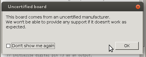 But before that, it’s time to bid farewell to the cheeky little popup window that would deliver a warning message when using a board bearing the USB IDs of their former-partner-turned-competitor. We absolutely


