Posts | Comments

Planet Arduino

Archive for the ‘pic’ Category

I’ve always appreciated simulation tools. Sure, there’s no substitute for actually building a circuit but it sure is handy if you can fix a lot of easy problems before you start soldering and making PCBs. I’ve done quite a few posts on LTSpice and I’m also a big fan of the Falstad simulator in the browser. However, both of those don’t do a lot for you if a microcontroller is a major part of your design. I recently found an open source project called Simulide that has a few issues but does a credible job of mixed simulation. It allows you to simulate analog circuits, LCDs, stepper and servo motors and can include programmable PIC or AVR (including Arduino) processors in your simulation.

The software is available for Windows or Linux and the AVR/Arduino emulation is built in. For the PIC on Linux, you need an external software simulator that you can easily install. This is provided with the Windows version. You can see one of several videos available about an older release of the tool below. There is also a window that can compile your Arduino code and even debug it, although that almost always crashed for me after a few minutes of working. As you can see in the image above, though, it is capable of running some pretty serious Arduino code as long as you aren’t debugging.

Looks and sounds exciting, right? It is, but be sure to save often. Under Linux, it seems to crash pretty frequently even if you aren’t debugging. It also suffers from other minor issues like sometimes forgetting how to move components. Saving, closing the application, and reopening it seems to fix that. Plus, we assume they will squash bugs as they are reported. One of my major hangs was solved by removing the default (old) Arduino IDE and making sure the most recent was on the path. But the crashing was frequent and seemed more or less random. It seemed that I most often had crashes on Linux with occasional freezes but on Windows it would freeze but not totally crash.

Basic Operation

The basic operation is pretty much what you’d expect. The window is broadly divided into three panes. The leftmost pane shows, by default, a palette of components. You can use the vertical tab strip on the left to also pick a memory viewer, a property inspector, or a file explorer.

The central pane is where you can draw your circuit and it looks like a yellow piece of engineering paper with a grid. Along the top are file buttons that do things like save and load files.

You’ll see a similar row of buttons above the rightmost pane. This is a code editor and debugging window that can interface with the Arduino IDE. It looks like it can also interface with GCBasic for the PIC, although I didn’t try that.

You drag components from the left onto the circuit. Wiring isn’t a distinct operation. You just let the mouse float over the connection until the cursor makes a cross. Click and then drag to the connection point and click again. Sometimes the program forgets to make the cross cursor and then I’ve had to save and restart.

Most of the components are just what you think they are. There are some fun ones including a keypad, an LED matrix, text and graphic LCDs, and even stepper and servo motors. You’ll also find several logic functions, 7400-series ICs, and there are annotation tools like text and boxes at the very bottom. You can right click on a category and hide components you never want to see.

At the top, you can add a voltmeter, an ammeter, or an oscilloscope to your circuit. The oscilloscope isn’t that useful because it is small. What you really want to do is use a probe. This just shows the voltage at some point but you can right click on it and add the probe to the plotter which appears at the bottom of the screen. This is a much more useful scope option.

There are a few quirks with the components. The voltage source has a push button that defaults to off. You have to remember to turn it on or things won’t work well. The potentiometers were particularly frustrating. The videos of older versions show a nice little potentiometer knob and that appears on my Windows laptop, too. On Linux the potentiometer (and the oscilloscope controls) look like a little tiny joystick and it is very difficult to set a value. It is easier to right click and select properties and adjust the value there. Just note that the value won’t change until you leave the field.

Microcontroller Features

If that’s all there was to it, you’d be better off using any of a number of simulators that we’ve talked about before. But the big draw here is being able to plop a microcontroller down in your circuit. The system provides PIC and AVR CPUs that are supported by the simulator code it uses. There’s also four variants of Arduinos: the Uno, Nano, Duemilanove, and the Leonardo.

You can use the built-in Arduino IDE — just make sure you have the real Arduino software on your path and it is a recent version. Also, unlike the real IDE, it appears you must save your file before a download or debug will notice the changes. In other words, if you make a change and download, you’ll compile the code before the change if you didn’t save the file first. You don’t have to use the built-in IDE. You can simply right click on the processor and upload a hex file. Recent Arduino IDEs have an option to export a hex file, and that works with no problem.

When you have a CPU in your design, you can right click it and open a serial monitor port which shows virtual serial output at the bottom of the screen and lets you provide input.

The debugging mode is simple but works until it crashes. Even without debugging, there is an option to the left of the screen to watch memory locations and registers inside the CPU.

Overall, the Arduino simulation seemed to work quite well. Connecting to the Uno pins was a little challenging at certain scales and I accidentally wired to the wrong pin on more than one occasion. One thing I found odd is that you don’t need to wire the voltage to the Arduino. It is powered on even if you don’t connect it.

Besides the crashing, the other issue I had was with the simulation speed which was rather slow. There’s a meter at the top of the screen that shows how slow the simulation is compared to real-time and mine was very low (10% or so) most of the time. There is a help topic explaining that this depends if you have certain circuit elements and ways to improve the run time, but it wasn’t bad enough that I bothered to explore it.

My first thought was that it would be difficult to handle a circuit with multiple CPUs in it since the debugging and serial monitors are all set up for a single CPU. However, as the video below shows, you can run multiple instances of the program and connect them via a serial port connection. The only issue would be if you had a circuit where both CPUs were interfacing with interrelated circuitry (for example, an op amp summing two signals, one from each CPU).

A Simple Example

As an experiment, I created a simple circuit that uses an Uno. It generates two PWM signals, integrates them with an RC circuit and then either drives a load or drives a load through a bipolar emitter follower. A pot lets you set the PWM percentages which are compliments of each other (that is, when one is at 10% the other is at 90%). Here’s the circuit:

Along with the very simple code:

int v;

const int potpin=0;
const int led0=5;
const int led1=6;

void setup() {
Serial.begin(9600);
Serial.println("Here we go!");
}

void loop() {
int v=analogRead(potpin)/4;
Serial.println(v);
analogWrite(led0,v);
analogWrite(led1,255-v);
delay(250);
}

Note that if the PWM output driving the transistor drops below 0.7V or so, the transistor will shut off. I deliberately didn’t design around that because I wanted to see how the simulator would react. It correctly models this behavior.

There’s really no point to this other than I wanted something that would work out the analog circuit simulation as well as the Arduino. You can download all the files from GitHub, including the hex file if you want to skip the compile step.

If you use the built-in IDE on the right side of the screen, then things are very simple. You just download your code. If you build your own hex file, just right click on the Arduino and you’ll find an option to load a hex file. It appears to remember the hex file, so if you run a simulation again later, you don’t have to repeat that step unless you moved the hex file.

However, the IDE doesn’t remember settings for the plotter, the voltage switches, or the serial terminal. You’ll especially want to be sure the 5V power switch above the transistor is on or that part of the circuit won’t operate correctly. You can right click on the Arduino to open the serial monitor and right click on the probes to bring back the plotter pane.

The red power switch at the top of the window will start your simulation. The screenshots above show close-ups of the plot pane and serial monitor.

Lessons Learned

This could be a really great tool if it would not crash so much. In all fairness, that could have something to do with my PC, but I don’t think that fully accounts for all of them. However, the software is still in pretty early development, so perhaps it will get better. There are a lot of fit and finish problems, too. For example, on my large monitor, many of the fonts were too large for their containers, which isn’t all that unusual.

The user interface seemed a little clunky, especially when you had to manipulate potentiometers and switches. Also, remember you can’t right-click on the controls but must click on the underlying component. In other words, the pot looks like a knob on top of a resistor. Right clicks need to go on the resistor part, not the knob. I also was a little put off that you can’t enter multiplier suffixes directly in component values. That is, you can’t enter a resistor value as 1K. You can enter 1000 or you can enter 1 and then change the units in a separate field to Kohms. But that’s not a big deal. You can get used to all of that if it would quit crashing.

I really wanted the debugging feature to work. While you can debug directly with simuavr or other tools, you can’t easily simulate all your I/O devices like you can with this tool. I’m hoping that becomes more robust in the future. Under Linux it would work for a bit and crash. On Windows, I never got it to work.

As I always say, though, simulation is great, but the real world often leads to surprises that don’t show up in simulation. Still, a simulation can help you clear up a host of problems before you commit to heating up the soldering iron or pulling out the breadboard. Simuide has the potential to be a great tool for simulating the kind of designs we see most on Hackaday.

If you want to explore other simulation options, we’ve talked a lot about LTSpice, including our Circuit VR series. There’s also the excellent browser-based Falstad simulator.

Before the Arduino took over the hobby market (well, at least the 8-bit segment of it), most hackers used PIC processors. They were cheap, easy to program, had a good toolchain, and were at the heart of the Basic Stamp, which was the gateway drug for many microcontroller developers.

[AXR AMR] has been working with the Pinguino, an Arduino processor based on a PIC (granted, an 18F PIC, although you can also use a 32-bit device, too). He shows you how to build a compatible circuit on a breadboard with about a dozen parts. The PIC has built-in USB. Once you flash the right bootloader, you don’t need anything other than a USB cable to program. You can see a video of this below.

You will need a programmer to get the initial bootloader, but there’s plenty of cheap options for that. The IDE is available for Windows, Linux, and the Mac. Of course, you might wonder why you would use a PIC device instead of the more traditional Arduino devices. The answer is: it depends. Every chip has its own set of plusses and minuses from power consumption to I/O devices, to availability and price. These chips might suit you, and they might not. That’s your call.  Of course, the difference between Microchip and Atmel has gotten less lately, too.

We’ve covered Pinguino before with a dedicated board. If you never played with a Basic Stamp, you might enjoy learning more about it. If you’re looking for more power than a PIC 18F can handle, you might consider the Fubarino, a PIC32 board you can use with the Arduino IDE.


Filed under: Arduino Hacks, Microcontrollers
En mis visitas diarias a otros blogs he encontrado una buena información en www.pighixxx.com y www.akafugu.jp que creo que puede ser de ayuda a toda aquella gente que comienza en esto de la electrónica y en concreto en el tema de Arduino. Se trata de unos documentos que he recopilado en un único pdf para […]
Jun
03

Kit review – Altronics/SC PIC Logic Probe Kit

altronics, chip, K2587, kit, kit review, logic, pic, probe, review, silicon, SMT, soldering, test equipment, tronixstuff Comments Off on Kit review – Altronics/SC PIC Logic Probe Kit 

Introduction

Every month Australian electronics magazine Silicon Chip publishes a few projects, and in this quick kit review we’ll look at an older but still current example from September 2007 – the 3-state PIC Logic Probe Kit. This is an inexpensive piece of test equipment that’s useful when checking digital logic states and as a kit, a challenging hand-soldering effort.

Assembly

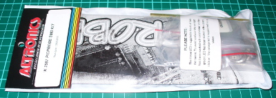
The kit is packaged in typical form, without any surprises:

kitpack

As mentioned earlier this kit is an interesting challenge due to the size of the PCB and the use of surface-mount components. The designer’s goal was to have the entire unit fit inside a biro housing (without the ink!). Thus the entire thing is using SMT parts.

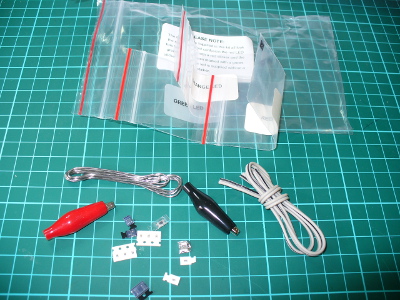
Thankfully the LEDs are packaged individually into labelled bags, as alone they’re identical to the naked eye. Although the kit wasn’t expensive, it would have been nice for one extra component of each type – beginners tend to lose the tiny parts. The cost could perhaps be offset by not including the usual solder which is too thick for use with the kit.

parts

Nevertheless with some care assembly can begin. After cleaning the PCB with some aerosol cleaner, it was tacked it to the desk mat to make life a little easier:

pcb

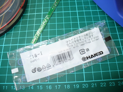
If you want one of those rulers – click here. Before building the kit it occurred to me that the normal soldering iron tip would be too large, so I ordered a tiny 0.2mm conical tip for the Hakko:

newtip

The tip on your average iron may be too large, so take this into account when trying to hand solder SMT components. The instructions include a guide on SMT hand-soldering for the uninitiated, well worth reading before starting.

Moving forward, soldering the parts was a slow and patient process. (With hindsight one could use the reflow soldering method to take care of the SMT and then carefully fit the links to the PCB). The instructions are quite good and include a short “how to solder SMT” guide, a PCB layout plan:

instructions

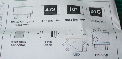
… along with an guide that helps identity the components:

instructionssmt

When soldering, make sure you have the time and patience not to rush the job. And don’t sneeze – after doing so I lost the PIC microcontroller for a few moments trying to find where it landed. Once the LEDs have been soldered in and their current-limiting resistors, it’s a good time to quickly test them by applying 5V and GND. I used the diode test feature of the multimeter which generates enough current to light them up.

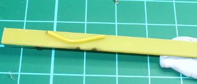
Due to the PCB being single-sided (!) you also need to solder in some links. It’s best to do these before the button (and before soldering any other parts near the link holes), and run the wires beneath the top surface, for example:

links

… and after doing so, you’ll need more blu-tack to hold it down!

gettingthere

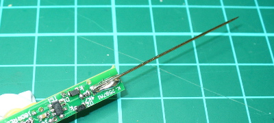
One of the trickiest parts of this kit was soldering the sewing needle at the end of the PCB to act as the probe tip – as you can see in the photo below, solder doesn’t take to them that well – however after a fair amount it does the job:

needle

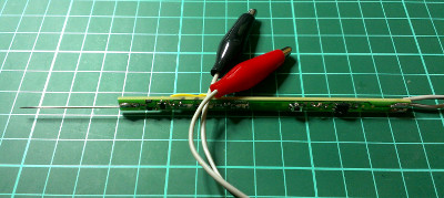
At this point it’s recommended you solder the wires to the PCB (for power) and then insert the probe into the pen casing. For the life of me I didn’t have a spare pen around here so instead we’re going to cover it in clear heatshrink. Thus leaving the final task as soldering the alligator clips to the power wires:

finished

Operation

What is a logic probe anyway? It shows what the logic level is at the probed point in a circuit. To do this you connect the black and red alligator clips to 0V and a supply voltage up to 18V respectively – then poke the probe tip at the point where you’re curious about the voltage levels. If it’s at a “high” state (on, or “1″ or whatever you want to call it) the red LED comes on.

If it’s “low” the green LED comes on. The third (orange) LED has two modes. It can either pulse every 50 mS when the logic state changes – or in “latch mode” it will come on and stay on when the mode changes, ideal for detecting infrequent changes in the logic state of the test point.

The kit uses a Microchip PIC12F20x microcontroller, and also includes the hardware schematic to make a basic RS232 PIC programmer and wiring instructions for reprogramming it if you want to change the code or operation of the probe.

Conclusion

The PIC Logic Probe is a useful piece of equipment if you want a very cheap way to monitor logic levels. It wasn’t the easiest kit to solder, and if Altronics revised it so the PCB was double-sided and changed the parts layout, there would be more space to solder some parts and thus make the whole thing a lot easier.

Nevertheless for under $17 it’s worth it. You can purchase it from Altronics and their resellers, or read more about it in the September 2007 edition of Silicon Chip. Full-sized images available on flickr. This kit was purchased without notifying the supplier. And if you made it this far – check out my new book “Arduino Workshop” from No Starch Press.

In the meanwhile have fun and keep checking into tronixstuff.com. Why not follow things on twitterGoogle+, subscribe  for email updates or RSS using the links on the right-hand column? And join our friendly Google Group – dedicated to the projects and related items on this website. Sign up – it’s free, helpful to each other –  and we can all learn something.


Jun
03

Introduction

Every month Australian electronics magazine Silicon Chip publishes a few projects, and in this quick kit review we’ll look at an older but still current example from September 2007 – the 3-state PIC Logic Probe Kit. This is an inexpensive piece of test equipment that’s useful when checking digital logic states and as a kit, a challenging hand-soldering effort.

Assembly

The kit is packaged in typical form, without any surprises:

kitpack

As mentioned earlier this kit is an interesting challenge due to the size of the PCB and the use of surface-mount components. The designer’s goal was to have the entire unit fit inside a biro housing (without the ink!). Thus the entire thing is using SMT parts.

Thankfully the LEDs are packaged individually into labelled bags, as alone they’re identical to the naked eye. Although the kit wasn’t expensive, it would have been nice for one extra component of each type – beginners tend to lose the tiny parts. The cost could perhaps be offset by not including the usual solder which is too thick for use with the kit.

parts

Nevertheless with some care assembly can begin. After cleaning the PCB with some aerosol cleaner, it was tacked it to the desk mat to make life a little easier:

pcb

If you want one of those rulers – click here. Before building the kit it occurred to me that the normal soldering iron tip would be too large, so I ordered a tiny 0.2mm conical tip for the Hakko:

newtip

The tip on your average iron may be too large, so take this into account when trying to hand solder SMT components. The instructions include a guide on SMT hand-soldering for the uninitiated, well worth reading before starting.

Moving forward, soldering the parts was a slow and patient process. (With hindsight one could use the reflow soldering method to take care of the SMT and then carefully fit the links to the PCB). The instructions are quite good and include a short “how to solder SMT” guide, a PCB layout plan:

instructions

… along with an guide that helps identity the components:

instructionssmt

When soldering, make sure you have the time and patience not to rush the job. And don’t sneeze – after doing so I lost the PIC microcontroller for a few moments trying to find where it landed. Once the LEDs have been soldered in and their current-limiting resistors, it’s a good time to quickly test them by applying 5V and GND. I used the diode test feature of the multimeter which generates enough current to light them up.

Due to the PCB being single-sided (!) you also need to solder in some links. It’s best to do these before the button (and before soldering any other parts near the link holes), and run the wires beneath the top surface, for example:

links

… and after doing so, you’ll need more blu-tack to hold it down!

gettingthere

One of the trickiest parts of this kit was soldering the sewing needle at the end of the PCB to act as the probe tip – as you can see in the photo below, solder doesn’t take to them that well – however after a fair amount it does the job:

needle

At this point it’s recommended you solder the wires to the PCB (for power) and then insert the probe into the pen casing. For the life of me I didn’t have a spare pen around here so instead we’re going to cover it in clear heatshrink. Thus leaving the final task as soldering the alligator clips to the power wires:

finished

Operation

What is a logic probe anyway? It shows what the logic level is at the probed point in a circuit. To do this you connect the black and red alligator clips to 0V and a supply voltage up to 18V respectively – then poke the probe tip at the point where you’re curious about the voltage levels. If it’s at a “high” state (on, or “1″ or whatever you want to call it) the red LED comes on.

If it’s “low” the green LED comes on. The third (orange) LED has two modes. It can either pulse every 50 mS when the logic state changes – or in “latch mode” it will come on and stay on when the mode changes, ideal for detecting infrequent changes in the logic state of the test point.

The kit uses a Microchip PIC12F20x microcontroller, and also includes the hardware schematic to make a basic RS232 PIC programmer and wiring instructions for reprogramming it if you want to change the code or operation of the probe.

Conclusion

The PIC Logic Probe is a useful piece of equipment if you want a very cheap way to monitor logic levels. It wasn’t the easiest kit to solder, and if Altronics revised it so the PCB was double-sided and changed the parts layout, there would be more space to solder some parts and thus make the whole thing a lot easier.

Nevertheless for under $17 it’s worth it. You can purchase it from Altronics and their resellers, or read more about it in the September 2007 edition of Silicon Chip. Full-sized images available on flickr. This kit was purchased without notifying the supplier. And if you made it this far – check out my new book “Arduino Workshop” from No Starch Press.

LEDborder

In the meanwhile have fun and keep checking into tronixstuff.com. Why not follow things on twitterGoogle+, subscribe  for email updates or RSS using the links on the right-hand column? And join our friendly Google Group – dedicated to the projects and related items on this website. Sign up – it’s free, helpful to each other –  and we can all learn something.

The post Kit review – Altronics/SC PIC Logic Probe Kit appeared first on tronixstuff.

Pinguino Kit (actualmente en la versión v1.1) es un entorno que permite programar las placas Pinguino Pic gráficamente. Esta herramienta pretende convertirse en una herramienta de enseñanza de programación y electrónica digital básica, centrada en estas placas. Os dejo una captura del IDE de Pinguino Kit y un vídeo en el que podéis ver un […]
Feb
12

Introduction

Every month Australian electronics magazine Silicon Chip publishes a variety of projects, and in January 2013 they published the “Garbage Recycling Reminder” by John Clarke. Jaycar picked it up and now offers a kit, the subject of our review. This kit solves the old but recurring (for some) problem – which bin to put out, and when!

The kit offers a simple way of keeping track of the bin schedule, and is suitable for up to four bins. With a simple user-interface consisting of a button and LED for each bin – once setup the reminder can easily be used by anyone. It allows for weekly, fortnightly and alternate fortnights – which is perfect for almost every council’s schedule.

Assembly

The kit arrives in typical Jaycar fashion:

and includes everything you need, including an enclosure, front panel sticker and battery:

 The PCB is well done, and routed nicely to fit inside the enclosure:

Now to get started. The instructions included are a reprint of the magazine article, and as Jaycar have modified the kit a little, their notes and photos are also included. However there isn’t anything to worry about.

Assembly is straight-forward, the only annoying thing was the assumption that the constructor will use off-cuts for jumper links. Instead – use your own header pins:

Furthermore, when soldering in the resistors and 1N914 diodes next to the LEDs – leave them floating so you can move them a bit to make way for the LEDs:

This is also a good time to check the buttons line up with the holes drilled into the front panel (a template is included with the instructions):

At this point you can fit the LEDs to the PCB, and carefully match it up with the drilled lid. You are supplied with a red, green, yellow and blue LED – which generally match the bin lid colours from various councils. Screw the PCB into the lid then solder the LEDs in – after double-checking they protrude out of lid. Then insert the battery and make a final test:

If you made it that far, you can apply the sticker included to illustrate the front panel. To save time we cut the sticker up for a minimalist look. However you now need to set-up the jumpers before closing the box up. There is a set of three pins for each bin, and a jumper can bridge the first two or last two pins, or none. If you don’t bridge them – that bin is weekly. If you bridge the first two – that bin is fortnightly from the setup day. If you bridge the last two – that bin is fortnightly from the next week, for example:

So you can easily set it up for a weekly bin and an alternating-fortnight pair of bins. Once you’ve setup the jumpers, screw up the box and you’re done.

Operation

Once you’ve set the jumpers up as described earlier, you just need to execute the programming function at the time you want the reminders to start every week. For example, if your weekly collection is 4 AM on a Thursday – do the programming around 5pm Wednesday night – that will then be the time the LEDs start blinking. When you put out the appropriate bin, press the button below the matching bin LED to stop the blinking. You can control the number of bins – so if you only have two bins, only two LEDs will activate. The blinking period is eighteen hours, and you can adjust the start time via the buttons.

How it works

The circuit is based around a Microchip PIC16LF88 and has an incredibly low current draw, around 15 uA when the LEDs aren’t blinking. This allows the circuit to run for over two years on the included 3v coin cell battery. The internal clock is kept accurate to around 10 minutes per year using an external 32.768 kHz crystal. After a period of use the battery voltage may drop to a level insufficient to adequately power the LEDs, so each one has a voltage doubler by way of a diode and capacitor – very clever. This ensures LED brightness even with a low battery. For complete details purchase the kit or a copy of the January 2013 edition of Silicon Chip.

Now it sits next to the kettle, waiting for bin night…

Conclusion

Personally I needed this kit, so I’m a little biased towards it. However – it’s simple and it works. Kudos to John Clarke for his project. You can purchase it from Jaycar and their resellers, or read more about it in the January 2013 edition of Silicon Chip. Full-sized images available on flickr. This kit was purchased without notifying the supplier.

In the meanwhile have fun and keep checking into tronixstuff.com. Why not follow things on twitterGoogle+, subscribe  for email updates or RSS using the links on the right-hand column? And join our friendly Google Group – dedicated to the projects and related items on this website. Sign up – it’s free, helpful to each other –  and we can all learn something.

The post Kit Review – SC/Jaycar Garbage and Recycling Reminder appeared first on tronixstuff.

Jan
10

The PICnDuino Review

arduino, arduino hacks, pic, Pic and Arduino, PICnDuino, reviews Comments Off on The PICnDuino Review 

picnduino

For those of you that can’t make a decision between buying an Arduino and a PIC processor, [Brad] has come up with a novel solution, the PICnDuino. We’ve featured him before with his [Retroball] project, but this time Brad has been full funded on Kickstarter, and is pre-selling boards for delivery in March.

[HAD], specifically I, was fortunate enough to be sent one of the boards to try out early. I’ve worked with an Arduino before, but never a PIC processor, so read on to see if it was actually as easy as the tutorial video (at the end of the article) would have you believe it is to get started.

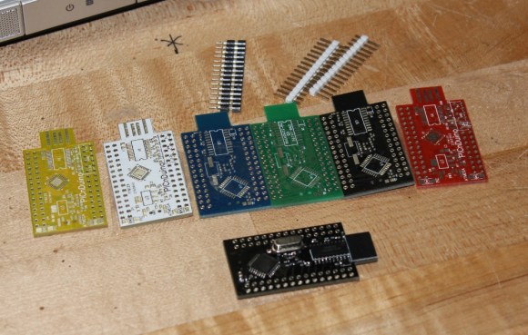
I was sent both a black board fully populated, as well as several blanks in the various colors pictured below.  After loosely attaching the headers, I found that the oscillator on the bottom makes the board sit up a bit when placed into a breadboard. This is actually a clever design feature to make sit up a bit to allow USB attachment while breadboarded. After a quick physical inspection, the real trick would be seeing if it worked as advertised.

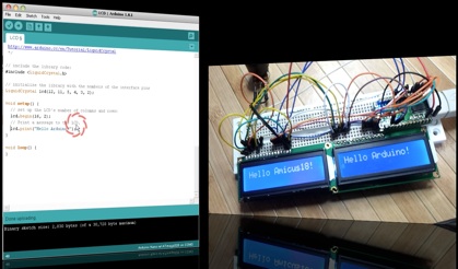
The first challenge for me was that, according to the documentation, this board runs in Windows or a virtualisation environment. I normally run Ubuntu, so, grabbing my wife’s circa 2000 vintage XP notebook, I downloaded and Amicus and Arduino software as explained in the video tutorial. The tutorial really spells out how to get the software running. This would be great for a total beginner, and made it so I didn’t have to even poke around for where to get the software.

picnduino-colors

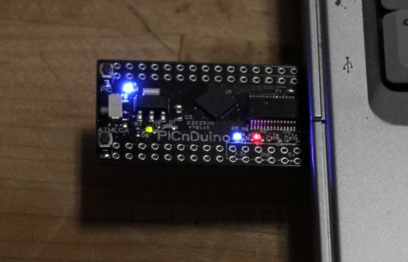
picnduino-in-usb

The only issue I had connecting to the board(s?)was that I had to manually install the Amicus18 USB driver. I’m a total noob when it comes to the PIC processor, and only have limited experience with the Arduino, but once the driver was updated, it was quite easy to get everything going.

After programming a “blink” sketch using it as an Arduino, I then flipped a switch and opened the Amicus IDE. Programming the PIC was also simple, although I had to use a and modify a program called “LED_Flash” to match the video instead of the “blink” program as described in the tutorial. It was a bit strange to see the built in blinking light for the Arduino still working while the PIC was being programmed, as well as both built-in lights blinking slightly offset while running simultaneously.

The documentation is extremely well done for a product that won’t even be available for delivery until March 2013. I’m really excited to play with it more, and I think it will be a great tool for people to either run two processors simultaneously, or just have the option of learning to program both a PIC and (n) Arduino. So check it out here, and get it shipped worldwide straight out of Australia!

Side note, bonus points if you can tell from the two pictures what kind of computer I used for this review!


Filed under: arduino hacks, reviews


  • Newsletter

    Sign up for the PlanetArduino Newsletter, which delivers the most popular articles via e-mail to your inbox every week. Just fill in the information below and submit.

  • Like Us on Facebook