Posts | Comments

Planet Arduino

Archive for the ‘assembler’ Category

I am a crappy software coder when it comes down to it. I didn’t pay attention when everything went object oriented and my roots were always assembly language and Real Time Operating Systems (RTOS) anyways.

So it only natural that I would reach for a true In-Circuit-Emulator (ICE) to finish of my little OBDII bus to speed pulse generator widget. ICE is a hardware device used to debug embedded systems. It communicates with the microcontroller on your board, allowing you to view what is going on by pausing execution and inspecting or changing values in the hardware registers. If you want to be great at embedded development you need to be great at using in-circuit emulation.

Not only do I get to watch my mistakes in near real time, I get to make a video about it also.

Getting Data Out of a Vehicle

I’ve been working on a small board which will plug into my car and give direct access to speed reported on the Controller Area Network (CAN bus).

To back up a bit, my last video post was about my inane desire to make a small assembly that could plug into the OBDII port on my truck and create a series of pulses representing the speed of the vehicle for my GPS to function much more accurately. While there was a wire buried deep in the multiple bundles of wires connected to the vehicle’s Engine Control Module, I have decided for numerous reasons to create my own signal source.

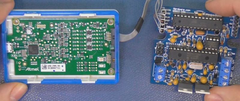
At the heart of my project is the need to convert the OBDII port and the underlying CAN protocol to a simple variable representing the speed, and to then covert that value to a pulse stream where the frequency varied based on speed. The OBDII/CAN Protocol is handled by the STN1110 chip and converted to ASCII, and I am using an ATmega328 like found on a multitude of Arduino’ish boards for the ASCII to pulse conversion. I’m using hardware interrupts to control the signal output for rock-solid, jitter-free timing.

Walk through the process of using an In-Circuit Emulator in the video below, and join me after the break for a few more details on the process.
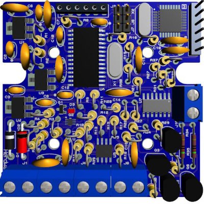
The Hardware

I revised the board since the last video and removed the support for the various protocols other than CAN, which is the non-obsolete protocol of the bunch. By removing a bunch of parts I was able to change the package style to through-hole which is easier for many home hobbyists, so you can leave the solder-paste in the ‘fridge.

The “Other Connector” on your Arduino

Unlike the Arduino which is ready to talk to your USB port when you take it out of the box, the ATmega chips arrive without any knowledge of how to go and download code, in other words it doesn’t have a boot loader. Consequently I have the In-Circuit-Serial-Programming (ICSP) pins routed to a pin header on my board so that I can program the part directly.

On this connector you’ll find the Reset line, which means with this header I can use a true ICE utilizing the debugWIRE protocol. Since the vast majority of designs that use an AVR chip do not repurpose the reset pin for GPIO, it is a perfect pin to use for ICE. All of the communications during the debug process will take place on the reset pin.

Enter the ICE

When designing a computer from scratch there is always the stage where nothing yet works. Simply put, a microprocessor circuit cannot work until almost every part of the design works; RAM, ROM, and the underlying buses all need to (mostly) work before simple things can be done. As a hardware engineer by trade I would always reach for an ICE to kick off the implementation; only after the Beta release would the ICE start to gather dust in the corner.

In the case of the ATmega, the debugging capabilities are built into the microcontroller itself. This is a much more straightforward implementation than the early days when we had to have a second isolated processor running off-board with its own local RAM/ROM.

One note mentioned in the video is that a standard Arduino’ish board needs to have the filter capacitors removed from the RESET line to allow the high speed data on the line for its debugWIRE usage.

The ICE I am using here is the one made by Atmel, and is compatible with Atmel Studio, there are also other models available such as the AVR Dragon.

ICEyness

The ICE allows us to download and single step our code while being able to observe and overwrite RAM and I/O Registers from the keyboard. We are able to watch the program step by step or look underneath at the actual assembly code generated by the compiler. We can watch variables and locations directly in RAM or watch the C language counterparts. It’s also possible to jump over a sub-routine call in the instance of just wanting to see the result without all of the processing.

It’s worth your time to see even a glimpse of the capabilities of an ICE in action. I recommend that you watch the video where the debugging begin.

Final Words

This video was really about finishing the OBDII circuit so I didn’t really have the time to go over everything an ICE can do, maybe I will do a post dedicated to just the ICE and development environment next time.


Filed under: Arduino Hacks, Hackaday Columns, Microcontrollers, Skills

Introduction

There are many types of microcontrollers on the market, and it would be fair to say one of the two most popular types is the Microchip PIC series. The PICs are great as there is a huge range of microcontrollers available across a broad range of prices. However learning how to get started with the PIC platform isn’t exactly simple. Not that we expect it to be, however a soft start is always better. There are some older books, however they can cost more than $100 – and are generally outdated. So where do you start?

It is with this problem in mind that led fellow Australian David Meiklejohn to develop and offer his PIC Training Course and Development Board to the marketplace via his company Gooligum Electronics.

In his words:

There is plenty of material available on PICs, which can make it daunting to get started.  And some of the available material is dated, originally developed before modern “flash” PICs were available, or based on older devices that are no longer the best choice for new designs.  Our approach is to introduce PIC programming and design in easy stages, based on a solid grounding in theory, creating a set of building blocks and techniques and giving you the confidence to draw on as we move up to more complex designs.

So in this article we’ll examine David’s course package. First of all, let’s look at the development board and inclusions. Almost everything you will need to complete all the lessons is included in the package, including the following PIC microcontrollers:

You can choose to purchase the board in kit form or pre-assembled. If you enjoy soldering, save the money and get the kit – it’s simple to assemble and a nice way to spend a few hours with a soldering iron.

Although the board includes all the electronic components and PICs – you will need are a computer capable of running Microchip MPLAB software, a Microchip PICkit3 (or -2) programming device and an IC extractor. If you’re building the kit, a typical soldering iron and so on will be required. Being the  ultra-paranoid type, I bought a couple extra of each PIC to have as spares, however none were damaged in my experimenting. Just use common-sense when handling the PICs and you will be fine.

Assembly

Putting the kit board together wasn’t difficult at all. There isn’t any surface-mount parts to worry about, and the PCB is silk-screened very well:

The rest of the parts are shipped in antistatic bags, appropriately labelled and protected:

Assembly was straight forward, just start with the low-profile parts and work your way up. The assembly guide is useful to help with component placement. After working at a normal pace, it was ready in just over an hour:

The Hardware

Once assembled (or you’ve opened the packaging) the various sections of the board are obvious and clearly labelled – as they should be for an educational board. You will notice a large amount of jumper headers – they are required to bridge in and out various LEDs, select various input methods and so on. A large amount of jumper shunts is included with the board.

It might appear a little disconcerting at first, but all is revealed and explained as you progress through the lessons. The board has decent rubber feet, and is powered either by the PICkit3 programmer, or a regulated DC power source between 5 and 6V DC, such as from a plug-pack if you want to operate your board away from a PC.

However there is a wide range of functions, input and output devices on the board – and an adjustable oscillator, as shown in the following diagram:

The Lessons

There is some assumed knowledge, which is a reasonable understanding of basic electronics, some computer and mathematical savvy and the C programming language.

You can view the first group of lessons for free on the kit website, and these are included along with the additional lessons in the included CDROM. They’re in .pdf format and easy to read. The CDROM also includes all the code so you don’t have to transcribe it from the lessons. Students start with an absolute introduction to the system, and first learn how to program in assembly language in the first group of tutorials, followed by C in the second set.

This is great as you learn about the microcontroller itself, and basically start from the bottom. Although it’s no secret I enjoy using the Arduino system – it really does hide a lot of the actual hardware knowledge away from the end user which won’t be learned. With David’s system – you will learn.

If you scroll down to the bottom of this page, you can review the tutorial summaries. Finally here’s a quick demonstration of the 7-segment displays in action:

Where to from here? 

Once you run through all the tutorials, and feel confident with your knowledge, the world of Microchip PIC will be open to you. Plus you now have a great development board for prototyping with 6 to 14-pin PIC microcontrollers. Don’t forget all the pins are brought out to the row of sockets next to the solderless breadboard, so general prototyping is a breeze.

Conclusion

For those who have mastered basic electronics, and have some C or C-like programming experience from using other development environments or PCs – this package is perfect for getting started with the Microchip PIC environment. Plus you’ll learn about assembly language – which is a good thing. I genuinely recommend this to anyone who wants to learn about PIC and/or move into more advanced microcontroller work. And as the entire package is cheaper than some books –  you can’t go wrong. The training course is available directly from the Gooligum website.

Disclaimer - The Baseline and Mid-Range PIC Training Course and Development Board was a promotional consideration from Gooligum Electronics.

In the meanwhile have fun and keep checking into tronixstuff.com. Why not follow things on twitterGoogle+, subscribe  for email updates or RSS using the links on the right-hand column? And join our friendly Google Group – dedicated to the projects and related items on this website. Sign up – it’s free, helpful to each other –  and we can all learn something.


Introduction

[Updated 18/06/2013]

There are many types of microcontrollers on the market, and it would be fair to say one of the two most popular types is the Microchip PIC series. The PICs are great as there is a huge range of microcontrollers available across a broad range of prices. However learning how to get started with the PIC platform isn’t exactly simple. Not that we expect it to be, however a soft start is always better. There are some older books, however they can cost more than $100 – and are generally outdated. So where do you start?

It is with this problem in mind that led fellow Australian David Meiklejohn to develop and offer his PIC Training Course and Development Board to the marketplace via his company Gooligum Electronics.

In his words:

There is plenty of material available on PICs, which can make it daunting to get started.  And some of the available material is dated, originally developed before modern “flash” PICs were available, or based on older devices that are no longer the best choice for new designs.  Our approach is to introduce PIC programming and design in easy stages, based on a solid grounding in theory, creating a set of building blocks and techniques and giving you the confidence to draw on as we move up to more complex designs.

So in this article we’ll examine David’s course package. First of all, let’s look at the development board and inclusions. Almost everything you will need to complete all the lessons is included in the package, including the following PIC microcontrollers:

You can choose to purchase the board in kit form or pre-assembled. If you enjoy soldering, save the money and get the kit – it’s simple to assemble and a nice way to spend a few hours with a soldering iron.

Although the board includes all the electronic components and PICs – you will need are a computer capable of running Microchip MPLAB software, a Microchip PICkit3 (or -2) programming device and an IC extractor. If you’re building the kit, a typical soldering iron and so on will be required. Being the  ultra-paranoid type, I bought a couple extra of each PIC to have as spares, however none were damaged in my experimenting. Just use common-sense when handling the PICs and you will be fine.

Assembly

Putting the kit board together wasn’t difficult at all. There isn’t any surface-mount parts to worry about, and the PCB is silk-screened very well:

barepcbss

The rest of the parts are shipped in antistatic bags, appropriately labelled and protected:

allthebitsss

Assembly was straight forward, just start with the low-profile parts and work your way up. The assembly guide is useful to help with component placement. After working at a normal pace, it was ready in just over an hour:

finishedboardss

The Hardware

Once assembled (or you’ve opened the packaging) the various sections of the board are obvious and clearly labelled – as they should be for an educational board. You will notice a large amount of jumper headers – they are required to bridge in and out various LEDs, select various input methods and so on. A large amount of jumper shunts is included with the board.

It might appear a little disconcerting at first, but all is revealed and explained as you progress through the lessons. The board has decent rubber feet, and is powered either by the PICkit3 programmer, or a regulated DC power source between 5 and 6V DC, such as from a plug-pack if you want to operate your board away from a PC.

However there is a wide range of functions, input and output devices on the board – and an adjustable oscillator, as shown in the following diagram:

boardlayoutonceassembledss

The Lessons

There is some assumed knowledge, which is a reasonable understanding of basic electronics, some computer and mathematical savvy and the C programming language.

You can view the first group of lessons for free on the kit website, and these are included along with the additional lessons in the included CDROM. They’re in .pdf format and easy to read. The CDROM also includes all the code so you don’t have to transcribe it from the lessons. Students start with an absolute introduction to the system, and first learn how to program in assembly language in the first group of tutorials, followed by C in the second set.

This is great as you learn about the microcontroller itself, and basically start from the bottom. Although it’s no secret I enjoy using the Arduino system – it really does hide a lot of the actual hardware knowledge away from the end user which won’t be learned. With David’s system – you will learn.

If you scroll down to the bottom of this page, you can review the tutorial summaries. Finally here’s a quick demonstration of the 7-segment displays in action:

Update – 18/06/2013

David has continued publishing more tutorials for his customers every few months – including such topics as the EEPROM and pulse-width modulation. As part of the expanded lessons you can also get a pack which allows experimenting with electric motors that includes a small DC motor, the TI SN75441 h-bridge IC, N-channel and P-channel MOSFETS and more:

motorkit

So after the initial purchase, you won’t be left on your own. Kudos to David for continuing to support and develop more material for his customers.

Where to from here? 

Once you run through all the tutorials, and feel confident with your knowledge, the world of Microchip PIC will be open to you. Plus you now have a great development board for prototyping with 6 to 14-pin PIC microcontrollers. Don’t forget all the pins are brought out to the row of sockets next to the solderless breadboard, so general prototyping is a breeze.

Conclusion

For those who have mastered basic electronics, and have some C or C-like programming experience from using other development environments or PCs – this package is perfect for getting started with the Microchip PIC environment. Plus you’ll learn about assembly language – which is a good thing. I genuinely recommend this to anyone who wants to learn about PIC and/or move into more advanced microcontroller work. And as the entire package is cheaper than some books –  you can’t go wrong. The training course is available directly from the Gooligum website.

Disclaimer - The Baseline and Mid-Range PIC Training Course and Development Board was a promotional consideration from Gooligum Electronics.

In the meanwhile have fun and keep checking into tronixstuff.com. Why not follow things on twitterGoogle+, subscribe  for email updates or RSS using the links on the right-hand column? And join our friendly Google Group – dedicated to the projects and related items on this website. Sign up – it’s free, helpful to each other –  and we can all learn something.

The post Review: Gooligum Electronics PIC Training Course and Development Board appeared first on tronixstuff.


  • Newsletter

    Sign up for the PlanetArduino Newsletter, which delivers the most popular articles via e-mail to your inbox every week. Just fill in the information below and submit.

  • Like Us on Facebook