Posts | Comments

Planet Arduino

Archive for the ‘board’ Category

Sep
02

Let’s explore Arduino Yún’s unique features – Hardware review

arduino, Arduino Yún, board, Hardware, Linux, review, Wi-Fi, Yun Comments Off on Let’s explore Arduino Yún’s unique features – Hardware review 

Arduino Yún

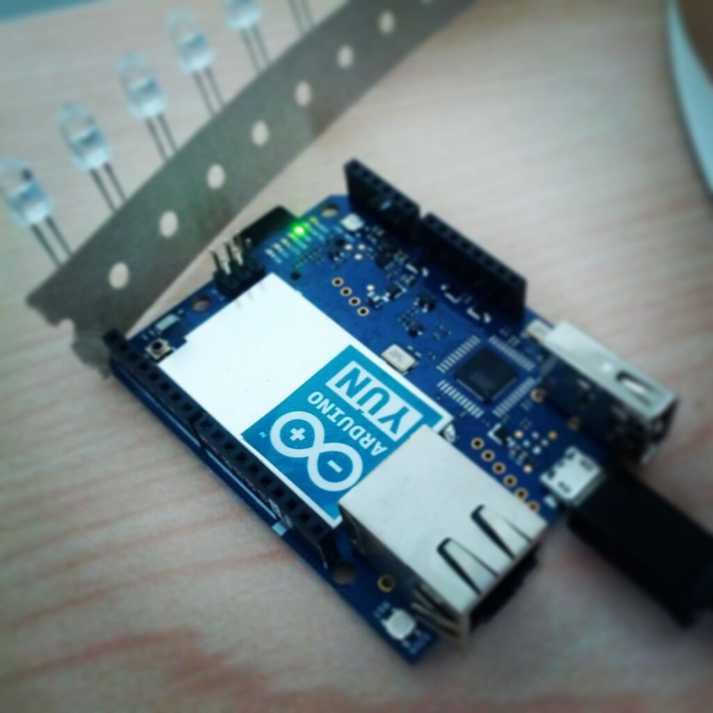
As announced a few days ago, the newest addition to the Arduino family, the Arduino Yún, will be available starting September 10. This is the first in a series of posts that will describe some of the Yún’s unique features. Today, we’ll focus on the hardware.

———————–

The Yún is unique in the Arduino lineup, as it has a lightweight Linux distribution to complement the traditional microcontroller interface. It also has WiFi and Ethernet connections on board, enabling it to communicate with networks out of the box. The Yún’s Linux and Arduino processors communicate through the Bridge library, allowing Arduino sketches to send commands to the command line interface of Linux.

Introduction
The Arduino Yún has the same footprint as an Arduino Uno but combines an ATmega32U4 microcontroller (the same as the Leonardo) and a Linux system based on the Atheros AR9331 chipset. Additionally, there are built-in Ethernet and WiFi capabilities. The combination of the classic Arduino programming experience and advanced internet capabilities afforded by a Linux system make the Yún a powerful tool for communicating with the internet of things.

The Yún’s layout keeps the I/O pins the same as the Arduino Leonardo. As such, the Yún is compatible with the most shields designed for Arduino.

With the Yún’s auto-discovery system, your computer can recognize boards connected to the same network. This enables you to upload sketches wirelessly to the Yún. You can still upload sketches to the Yún through the micro-USB connector just as you would with the Leonardo.

Connectivity
The Yún has two separate network interfaces, a 10/100 Mbit/s Fast Ethernet port and a IEEE 802.11 b/g/n standard compliant 2.4GHz WiFi interface, supporting WEP, WPA and WPA2 encryption. The WiFi interface can also operate as an access point (AP). In AP mode any WiFi enabled device can connect directly to the network created on the Yún. While a Yún in this mode can’t connect to the internet, it could act as a hub for a group of WiFi enabled sensors.

Historically, interfacing Arduino with web services has been challenging due to memory restrictions. The Yun’s Linux environment simplifies the means to access internet services by using many if the same tools you would use on your computer. You can run several applications as complex as you need, without stressing the ATmega microcontroller.

To help you develop applications that can connect to popular web services, we have partnered with Temboo, a service that simplifies accessing hundreds of the web’s most popular APIs. A Temboo library comes with the Yún, making it easy to connect to a large variety of online tools. Check out their website for the full list of services they offer.

Connection between the two processors
The Yún’s Bridge library enables communication between the two processors, connecting the hardware serial port of the AR9331 to Serial1 on the 32U4 (digital pins 0 & 1). Another post will describe the library in greater depth. The serial port of the AR9331 exposes the Linux console (aka, the command line interface, or CLI) for communication with the 32U4. The console is a means for the Linux kernel and other processes to output messages to the user and receive input from the user. File and system management tools are installed by default. It’s also possible to install and run your own applications using Bridge.

The ATmega32U4 can be programmed from the AR9331 by uploading a sketch through the Yún’s WiFi interface. When connected to the same WiFi network as your computer, the board will appear under the “Port” menu of the Arduino IDE. The sketch will be transferred to the AR9331, and the Linux distribution will program the ATmega32U4 through the SPI bus, emulating an AVR ISP programmer.

Power consideration
The Yún can be powered through the micro-USB connector, the Vin pin, or the optional Power Over Ethernet (POE) module. When powering the board though the Vin pin, you must supply a regulated 5VDC. There is no on-board voltage regulator for higher voltages.

Linux OS specifications
The Yún runs a version of the OpenWRT Linux distribution called Linino. The on-board 16MB flash memory that contains the Linux image has a full python installation and package manager you can use to install additional software.
The AR9331 has 64 MB of DDR2 RAM available, providing the resources to perform complex tasks like running a web server or streaming video from a webcam.
You can expand the storage memory by adding a micro-SD card or a USB pen drive. By including a directory named “arduino” at the root level of the storage device, it will be automatically recognized by the Yún.

USB Host
The Yún has a USB host port connected to the AR9331. You can connect USB peripherals like webcams, memory sticks, or joypads to this input. Generally, Linux has drivers included for the more common devices like mass storage or mice and keyboards. For more specific devices like webcams, you will need to refer to the device specifications to find the appropriate driver. As the USB port is connected to the Linux processor, it’s not directly accessible from sketches on the 32U4.

—————-

The next post about the Yún will focus on the Bridge library, describing how it facilitates communication between the two processors. Stay tuned!

Aug
28

Initial Review – Goldilocks Arduino-compatible with ATmega1284P

arduino, atmega1284p, atmel, board, compatible, freetronics, goldilocks, part review, review, tronixstuff Comments Off on Initial Review – Goldilocks Arduino-compatible with ATmega1284P 

Introduction

In March this year we discussed a project by Phillip Stevens to crowd-fund an Arduino-compatible board with an ATmega1284p microcontroller – the “Goldilocks”. After being funded at a rapid rate, and subjected to some community feedback – the boards have now been manufactured and delivered to those who pledged. If you missed out – there’s some more available for direct sales. We ordered five and now have them for the subject of this review – and two to give away. So let’s examine the board and see what’s new.

What is it?

After hitting the limits of the Arduino Uno with respect to SRAM, CPU speed and not wanting to lose compatibility with existing projects by changing platforms, Philip decided to shift the MCU up to the ATmega1284P. This offers eight times the SRAM, four times the flash memory and EEPROM – and is also clocked at 20 MHz instead of the usual 16 MHz on Unos, etc. After the original design was announced, it was the victim of some pretty heavy feature-creep – however with Freetronics as the manufacturing partner the final result is a nicely-finished product:

freetronics goldilocks

Now let’s rip open the packaging and examine the board in greater detail. From the images below you can get the gist of things… starting with the top you can see the ATmega1284P next to the microSD card socket. There’s a JTAG connector for the 1284P on its left – and below that a 32.768 kHz crystal for RTC use. And like other Freetronics boards a large prototyping area has been squeezed in below pins D0~7 that also has the power and I2C lines at the edge. Furthermore note that all I/O pins are brought out to separate holes in alignment with the header sockets. And my favourite – a switch-mode power supply circuit that can offer up to 2A of current – great for GSM shields.

freetronics goldilocks top

Another point of interest is the ATmega32U2 microcontroller which is for USB duties – however it can be used as a separate “board” on its own, with a separate reset button, ICSP breakout and the ports are broken out logically:

freetronics goldilocks atmega32u2

Furthermore the 32U2′s SPI bus can be wired over to the main 1284P to allow communication between the two – simply by bridging the provided pads on the PCB you can join them. Also on the bottom you can see how each I/O pin can be disconnected from the I/O areas and thus diverted if necessary. It really is a testament to the design that so much of the board is customisable, and this attention to detail makes it stand apart from the usual Arduino-compatibles out there.

freetronics goldilocks bottom

One thing that did strike me was the retina-burning intensity of the onboard LEDs – however you can disable them by cutting the provided track on the PCB. For a complete explanation of the hardware side of things, check out the user guide.

Using the Goldilocks

One of the main goals was to be Arduino Uno R3-compatible, and from initial examination this is certainly the case. However there are a couple of differences, which you can find out more about in the user guide. This is not the first board for an Arduino user, but something chosen after getting some experience. Installation was very easy, it should be plug-and-play for the non-Windows crowd. However if you’re part of the silent majority of Windows users then the required U2duino Programmer.inf file for the Device Manager will be found in the production_firmware folder of the software download available on the product page. Furthermore no matter your OS – don’t forget to install the Arduino IDE Goldilocks board profile.

Before getting too excited and uploading your sketches, you can examine the the ATmega1284p bootloader monitor which allows for memory dumps, port testing, and more. Simply connect up your board, load the Arduino IDE, select the board and COM: port then open the Serial Monitor. By sending “!!!” after a board reset, a simple menu appears – which is shown in the following video:

Now for a quick speed test. We’ll use a sketch written by Steve Curd from the Arduino forum. It calculates Newton Approximation for pi using an infinite series:

// Pi_2 by Steve Curd // December 2012
// This program approximates pi utilizing the Newton's approximation.  It quickly
// converges on the first 5-6 digits of precision, but converges verrrry slowly
// after that.  For example, it takes over a million iterations to get to 7-8
// significant digits.

#define ITERATIONS 100000L    // number of iterations
#define FLASH 1000            // blink LED every 1000 iterations

void setup() 
{
  pinMode(13, OUTPUT);        // set the LED up to blink every 1000 iterations
  Serial.begin(57600);
}

void loop() 
{
  unsigned long start, time;
  unsigned long niter=ITERATIONS;
  int LEDcounter = 0;
  boolean alternate = false;
  unsigned long i, count=0;
  float x = 1.0;
  float temp, pi=1.0;
  Serial.print("Beginning ");
  Serial.print(niter);
  Serial.println(" iterations...");
  Serial.println();
  start = millis();  
  for ( i = 2; i < niter; i++) {
    x *= -1.0;
    pi += x / (2.0f*(float)i-1.0f);
    if (LEDcounter++ > FLASH) {
      LEDcounter = 0;
      if (alternate) {
        digitalWrite(13, HIGH);
        alternate = false;
      } else {
        digitalWrite(13, LOW);
        alternate = true;
      }
      temp = 40000000.0 * pi;
    }
  }
  time = millis() - start;
  pi = pi * 4.0;
  Serial.print("# of trials = ");
  Serial.println(niter);
  Serial.print("Estimate of pi = ");
  Serial.println(pi, 10);
  Serial.print("Time: "); Serial.print(time); Serial.println(" ms");
  delay(10000);
}

The Goldilocks was compared with a standard Arduino Uno, with the following results (click image to enlarge):

goldilocks Uno speed test

 As you can see from the results below, the Goldilocks theoretical extra 4 Mhz of speed is shown in the elapsed time between the two boards – 4433 ms for the Goldilocks vs. 5562 ms for the Uno, a 25.4% increase. Looking good. We’ll leave it for now – however for more information you can review the complete user manual, and also discuss Goldilocks in the Freetronics customer forum.

Competition

Two of our twitter followers will be randomly selected on the 14th of September, and will each receive one Goldilocks board. So follow us on @tronixstuff for a chance to win a board, and also keep up with news, new articles and items of interest. Board will be delivered by Australia Post standard air mail. We’re not responsible for customs or import duties, VAT, GST, import duty, postage delays, non-delivery or whatever walls your country puts up against receiving inbound mail.

Conclusion

The Goldilocks is the board that can solve many problems – especially when you’ve outgrown your Uno or similar board. We look forward to using it with larger projects that burn up SRAM and exploring the possibilities of using the two microcontrollers at once. There’s a whole bundle of potential – so congratulations to Phillip Stevens, Freetronics and all those who pledge to the funding and supported the project in general. And to join in – you can get your own from Freetronics. Full-sized images are on flickr. And if you made it this far – check out my new book “Arduino Workshop” from No Starch Press.

In the meanwhile have fun and keep checking into tronixstuff.com. Why not follow things on twitterGoogle+, subscribe  for email updates or RSS using the links on the right-hand column? And join our friendly Google Group – dedicated to the projects and related items on this website. Sign up – it’s free, helpful to each other –  and we can all learn something.

The post Initial Review – Goldilocks Arduino-compatible with ATmega1284P appeared first on tronixstuff.

Aug
21

Updating about Arduino Yún (video preview!) and Arduino Robot

Announcements, arduino, board, Linux, Wi-Fi, Yun Comments Off on Updating about Arduino Yún (video preview!) and Arduino Robot 

Arduino Yún - Unboxing

Some months ago we announced that we were developing a new product to meet the growing demand for wi-fi, linux based boards. The blogpost on the upcoming Arduino YÚN was our most read ever, and since then the attention has stayed high.

Recently, some of you have been asking why the YÚN hasn’t come out yet and why the Arduino Robot is not yet available for purchase.

Simply put, moving to a wifi-enabled linux board is a whole new step for Arduino and it’s taking longer than we expected. Arduino YÚN  is our most complex product ever and we decided to working on getting it right regardless of timing.

The early prototypes boards mounted 8MB of Flash and 32MB of RAM. While we managed to implement most of the YÚN features previously planned inside this amount of memory, we were forced to use optimized versions of the most common software packages: smaller in size but missing a lot of cool features available in the “full” non-optimized version.

We also quickly discovered that there wasn’t plenty of free space remaining for the user to install additional packages or to run complex programs without incurring in stability problems.

Considering this we finally decided to double both Flash and RAM, giving a comfortable 16MB of Flash and 64MB of RAM.

We try our best to get everything done as soon as possible while still providing the quality that we hope distinguishes Arduino products.

The delay in the Arduino Robot is connected to that of YÚN and our distribution processes.

We are really happy about the new Arduino YÚN and we hope the community will be as well.

The board is going to be available on the Arduino Store from September the 10th, while being delivered to our distributors late this month. In the video below you can watch a  preview of the board with me and David Cuartielles giving some more details about it.


From the product pages on the Arduino Store,  for the YÚN and Robot, you can activate an alert that will send you an email when the product is available from the distributors.

Introduction

For those of you prototyping with larger Atmel AVR microcontrollers such as the ATmega32, it can be inconvenient to continually assemble a circuit onto a solderless breadboard that includes power, programming header and a few basics – or you might want to create a one-off product without waiting for a PCB to be made. If these are issues for you, or you’re interested in working with AVRs  then the subject of this review may be of interest – the ATmega32 Development Kit from Protostack. The kit is one of a range that spans from the ATmega8, and gives you almost everything needed to work with the microcontroller. We’ve assembled and experimented with the ATmega32 kit, so read on to find out more.

Assembly

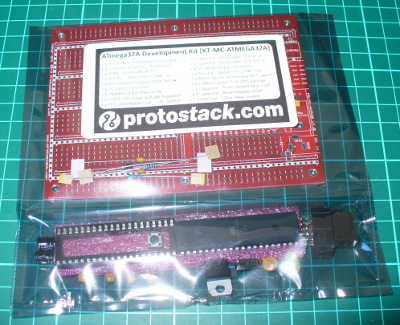
The kit arrives in a typical anti-static package with the contents and URL on the front:

packaging

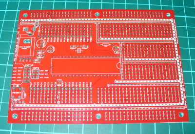
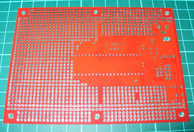
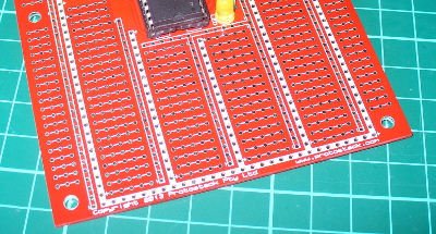
The PCB is large, measuring 127 x 94 mm, made from heavy 1.6 mm FR4 PCB and all the holes are through-plated. And as you can see from the images below, there’s plenty of prototyping space and power/GND rails:

pcbtop

pcbbottom

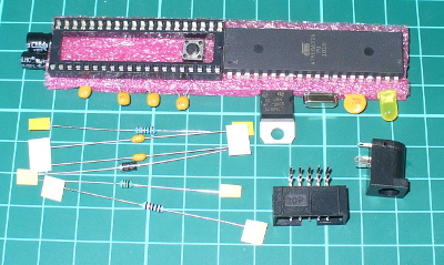
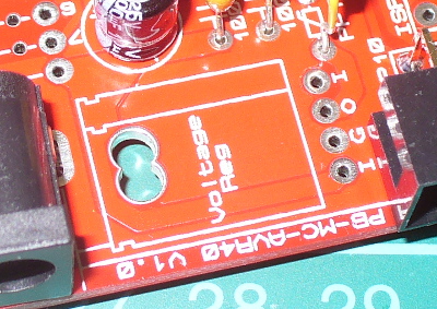
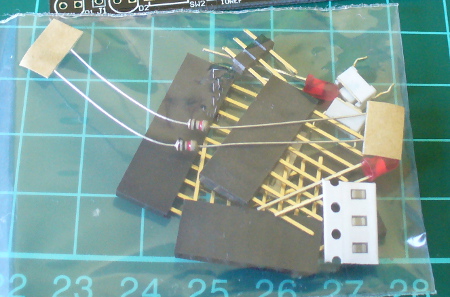
The included parts allow you to add a power supply, polyfuse, smoothing capacitors for the power, programmer socket, external 16 MHz crystal, a DC socket, IC socket, a lonely LED and of course the ATmega32A (which is a lower-power version of the ATmega32):

parts

You can download the user guide from the product page, which details the board layout, schematic and so on. When soldering the parts in, just start with the smallest-profile parts first and work your way up. There’s a few clever design points, such as power regulator – there’s four holes so you can use both “in-GND-output” and “GND-output-input” types:

igo

… and the layout of the prototyping areas resemble that of a solderless breadboard, and the power/GND rails snake all around – so transferring projects won’t be difficult at all:

protoarea

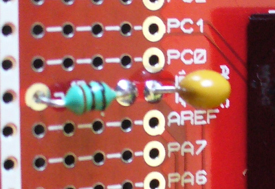
If you need to connect the AVcc to Vcc, the components and board space are included for a low-pass filter:

lowpass

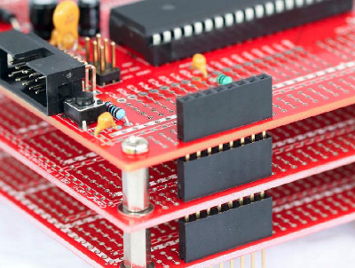
And if you get carried away and need to use two or more boards at once – they’re stackable:

stacking

Moving forward

After assembling the board and inserting the ATmega32, you can use an AVR programmer to check it’s all working (and of course program it). With a 10-pin interface USBASP inserted, I headed over to the AVRdude folder on my PC and entered:

avrdude -c usbasp -p m32

which (as all was well) resulted with:

avrdudetest

Awesome – it’s nice to have something that just works. Let the experimenting begin!

Competition

Would you like the chance to win a kit? It’s easy. Clearly print your email address on a postcard, and mail it to:

Protostack Competition, PO Box 5435, Clayton 3168, Australia

Entries must be received by the 4th of  August 2013. One postcard will then be drawn at random, and the winner will receive one ATmega32 kit delivered by Australia Post standard air mail. You can enter as many times as you like. We’re not responsible for customs or import duties, VAT, GST, postage delays, non-delivery or whatever walls your country puts up against receiving inbound mail.

Conclusion

It’s a solid kit, the PCB is solid as a rock, and it worked. However it could really have used some spacers or small rubber feet to keep the board off the bench. Otherwise the kit is excellent, and offers a great prototyping area to work with your projects. If you order some, Protostack have a maximum delivery charge of $9 so you won’t get burned on delivery to far-flung places.  Larger photos available on flickr. And if you made it this far – check out my new book “Arduino Workshop” from No Starch Press.

Please note that the ATMEGA32A Development Kit in this review is a promotional consideration from Protostack.

In the meanwhile have fun and keep checking into tronixstuff.com. Why not follow things on twitterGoogle+, subscribe  for email updates or RSS using the links on the right-hand column? And join our friendly Google Group – dedicated to the projects and related items on this website. Sign up – it’s free, helpful to each other –  and we can all learn something.


Introduction

For those of you prototyping with larger Atmel AVR microcontrollers such as the ATmega32, it can be inconvenient to continually assemble a circuit onto a solderless breadboard that includes power, programming header and a few basics – or you might want to create a one-off product without waiting for a PCB to be made. If these are issues for you, or you’re interested in working with AVRs  then the subject of this review may be of interest – the ATmega32 Development Kit from Protostack. The kit is one of a range that spans from the ATmega8, and gives you almost everything needed to work with the microcontroller. We’ve assembled and experimented with the ATmega32 kit, so read on to find out more.

Assembly

The kit arrives in a typical anti-static package with the contents and URL on the front:

packaging

The PCB is large, measuring 127 x 94 mm, made from heavy 1.6 mm FR4 PCB and all the holes are through-plated. And as you can see from the images below, there’s plenty of prototyping space and power/GND rails:

pcbtop

pcbbottom

The included parts allow you to add a power supply, polyfuse, smoothing capacitors for the power, programmer socket, external 16 MHz crystal, a DC socket, IC socket, a lonely LED and of course the ATmega32A (which is a lower-power version of the ATmega32):

parts

You can download the user guide from the product page, which details the board layout, schematic and so on. When soldering the parts in, just start with the smallest-profile parts first and work your way up. There’s a few clever design points, such as power regulator – there’s four holes so you can use both “in-GND-output” and “GND-output-input” types:

igo

… and the layout of the prototyping areas resemble that of a solderless breadboard, and the power/GND rails snake all around – so transferring projects won’t be difficult at all:

protoarea

If you need to connect the AVcc to Vcc, the components and board space are included for a low-pass filter:

lowpass

And if you get carried away and need to use two or more boards at once – they’re stackable:

stacking

Moving forward

After assembling the board and inserting the ATmega32, you can use an AVR programmer to check it’s all working (and of course program it). With a 10-pin interface USBASP inserted, I headed over to the AVRdude folder on my PC and entered:

avrdude -c usbasp -p m32

which (as all was well) resulted with:

avrdudetest2

Awesome – it’s nice to have something that just works. Let the experimenting begin!

Conclusion

It’s a solid kit, the PCB is solid as a rock, and it worked. However it could really have used some spacers or small rubber feet to keep the board off the bench. Otherwise the kit is excellent, and offers a great prototyping area to work with your projects. If you order some, Protostack have a maximum delivery charge of $9 so you won’t get burned on delivery to far-flung places.  Larger photos available on flickr. And if you made it this far – check out my new book “Arduino Workshop” from No Starch Press.

LEDborder

Please note that the ATMEGA32A Development Kit in this review is a promotional consideration from Protostack.

In the meanwhile have fun and keep checking into tronixstuff.com. Why not follow things on twitterGoogle+, subscribe  for email updates or RSS using the links on the right-hand column? And join our friendly Google Group – dedicated to the projects and related items on this website. Sign up – it’s free, helpful to each other –  and we can all learn something.

The post Kit review – Protostack ATmega32 Development Kit appeared first on tronixstuff.

In this article we review a couple of SMT prototyping boards from Schmartboard.

Introduction

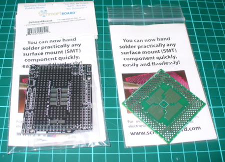
Sooner or later you’ll need to use a surface-mount technology component. Just like taxes and myki* not working, it’s inevitable. When the time comes you usually have a few options – make your own PCB, then bake it in an oven or skillet pan; get the part on a demo board from the manufacturer (expensive); try and hand-solder it yourself using dead-bug wiring or try to mash it into a piece of strip board; or find someone else to do it. Thanks to the people at Schmartboard you now have another option which might cost a few dollars more but guarantees a result. Although they have boards for almost everything imaginable, we’ll look at two of them – one for QFP packages and their Arduino shield that has SOIC and SOP23-6 areas.

boards

QFP 32-80 pin board

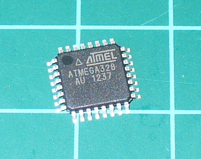
In our first example we’ll see how easy it is to prototype with QFP package ICs. An example of this is the Atmel ATmega328 microcontroller found on various Arduino-compatible products, for example:

atmega

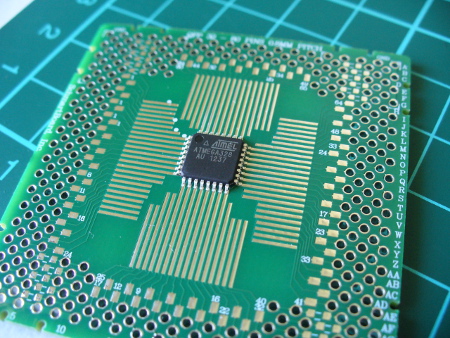
Although our example has 32 pins, the board can handle up to 80-pin devices. You simply place the IC on the Schmartboard, which holds the IC in nicely due to the grooved tracks for the pins:

atmegabefore

The tracks are what makes the Schmartboard EZ series so great – they help hold the part in, and contain the required amount of solder. I believe this design is unique to Schmartboard and when you look in their catalogue, select the “EZ” series for this technology. Moving forward, you just need some water-soluble flux:

fluxpen

then tack down the part, apply flux to the side you’re going to solder – then slowly push the tip of your soldering iron (set to around 750 degrees F) down the groove to the pin. For example:

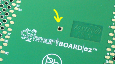
Then repeat for the three other sides. That’s it. If your part has an exposed pad on the bottom, there’s a hole in the centre of the Schmartboad that you can solder into as well:

qfpheat

After soldering I really couldn’t believe it worked, so probed out the pins to the breakout pads on the Schmartboard to test for shorts or breaks – however it tested perfectly. The only caveat is that your soldering iron tip needs to be the same or smaller pitch than the the part you’re using, otherwise you could cause a solder bridge. And use flux!  You need the flux. After soldering you can easily connect the board to the rest of your project or build around it.

Schmartboard Arduino shield

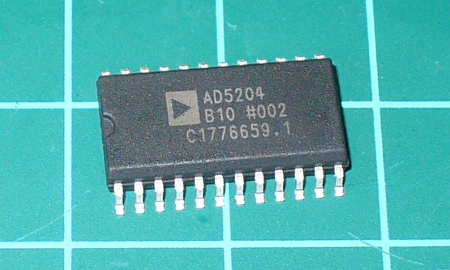
There’s also a range of Arduino shields with various SMT breakout areas, and we have the version with 1.27mm pitch SOIC and a SOT23-6 footprint. SOIC? For example:

soicic

This is the AD5204 four-channel digital potentiometer we used in the SPI tutorial. It sits nicely in the shield and can be easily soldered onto the board. Don’t forget the flux! Although the SMT areas have the EZ-technology, I still added a little solder of my own – with satisfactory results:

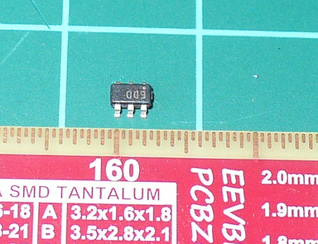
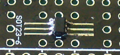
The SOT23-6 also fits well, with plenty of space for soldering it in. SOT23? Example – the ADS1110 16-bit ADC which will be the subject of a future tutorial:

ads1110

Working with these tiny components is also feasible but requires a finer iron tip and a steady hand.

sot236

Once the SMT component(s) have been fitted, you can easily trace out the matching through-hole pads for further connections. The shield matches the Arduino R3 standards and includes stacking header sockets, two LEDs for general use, space and parts for an RC reset circuit, and pads to add pull-up resistors for the I2C bus:

otherparts

Finally there’s also three 0805-sized parts and footprints for some practice or use. It’s a very well though-out shield and should prove useful. You can also order a bare PCB if you already have stacking headers to save money.

Conclusion

If you’re in a hurry to prototype with SMT parts, instead of mucking about – get a Schmartboard. They’re easy to use and work well.  Full-sized images available on flickr.

In the meanwhile have fun and keep checking into tronixstuff.com. Why not follow things on twitterGoogle+, subscribe  for email updates or RSS using the links on the right-hand column? And join our friendly Google Group – dedicated to the projects and related items on this website. Sign up – it’s free, helpful to each other –  and we can all learn something.

The boards used in this article were a promotional consideration supplied by Schmartboard.

*myki

The post Review – Schmartboard SMT Boards appeared first on tronixstuff.

Introduction

There are many types of microcontrollers on the market, and it would be fair to say one of the two most popular types is the Microchip PIC series. The PICs are great as there is a huge range of microcontrollers available across a broad range of prices. However learning how to get started with the PIC platform isn’t exactly simple. Not that we expect it to be, however a soft start is always better. There are some older books, however they can cost more than $100 – and are generally outdated. So where do you start?

It is with this problem in mind that led fellow Australian David Meiklejohn to develop and offer his PIC Training Course and Development Board to the marketplace via his company Gooligum Electronics.

In his words:

There is plenty of material available on PICs, which can make it daunting to get started.  And some of the available material is dated, originally developed before modern “flash” PICs were available, or based on older devices that are no longer the best choice for new designs.  Our approach is to introduce PIC programming and design in easy stages, based on a solid grounding in theory, creating a set of building blocks and techniques and giving you the confidence to draw on as we move up to more complex designs.

So in this article we’ll examine David’s course package. First of all, let’s look at the development board and inclusions. Almost everything you will need to complete all the lessons is included in the package, including the following PIC microcontrollers:

You can choose to purchase the board in kit form or pre-assembled. If you enjoy soldering, save the money and get the kit – it’s simple to assemble and a nice way to spend a few hours with a soldering iron.

Although the board includes all the electronic components and PICs – you will need are a computer capable of running Microchip MPLAB software, a Microchip PICkit3 (or -2) programming device and an IC extractor. If you’re building the kit, a typical soldering iron and so on will be required. Being the  ultra-paranoid type, I bought a couple extra of each PIC to have as spares, however none were damaged in my experimenting. Just use common-sense when handling the PICs and you will be fine.

Assembly

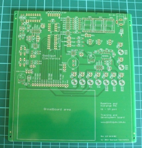
Putting the kit board together wasn’t difficult at all. There isn’t any surface-mount parts to worry about, and the PCB is silk-screened very well:

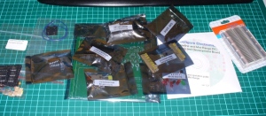
The rest of the parts are shipped in antistatic bags, appropriately labelled and protected:

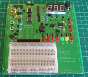
Assembly was straight forward, just start with the low-profile parts and work your way up. The assembly guide is useful to help with component placement. After working at a normal pace, it was ready in just over an hour:

The Hardware

Once assembled (or you’ve opened the packaging) the various sections of the board are obvious and clearly labelled – as they should be for an educational board. You will notice a large amount of jumper headers – they are required to bridge in and out various LEDs, select various input methods and so on. A large amount of jumper shunts is included with the board.

It might appear a little disconcerting at first, but all is revealed and explained as you progress through the lessons. The board has decent rubber feet, and is powered either by the PICkit3 programmer, or a regulated DC power source between 5 and 6V DC, such as from a plug-pack if you want to operate your board away from a PC.

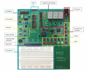
However there is a wide range of functions, input and output devices on the board – and an adjustable oscillator, as shown in the following diagram:

The Lessons

There is some assumed knowledge, which is a reasonable understanding of basic electronics, some computer and mathematical savvy and the C programming language.

You can view the first group of lessons for free on the kit website, and these are included along with the additional lessons in the included CDROM. They’re in .pdf format and easy to read. The CDROM also includes all the code so you don’t have to transcribe it from the lessons. Students start with an absolute introduction to the system, and first learn how to program in assembly language in the first group of tutorials, followed by C in the second set.

This is great as you learn about the microcontroller itself, and basically start from the bottom. Although it’s no secret I enjoy using the Arduino system – it really does hide a lot of the actual hardware knowledge away from the end user which won’t be learned. With David’s system – you will learn.

If you scroll down to the bottom of this page, you can review the tutorial summaries. Finally here’s a quick demonstration of the 7-segment displays in action:

Where to from here? 

Once you run through all the tutorials, and feel confident with your knowledge, the world of Microchip PIC will be open to you. Plus you now have a great development board for prototyping with 6 to 14-pin PIC microcontrollers. Don’t forget all the pins are brought out to the row of sockets next to the solderless breadboard, so general prototyping is a breeze.

Conclusion

For those who have mastered basic electronics, and have some C or C-like programming experience from using other development environments or PCs – this package is perfect for getting started with the Microchip PIC environment. Plus you’ll learn about assembly language – which is a good thing. I genuinely recommend this to anyone who wants to learn about PIC and/or move into more advanced microcontroller work. And as the entire package is cheaper than some books –  you can’t go wrong. The training course is available directly from the Gooligum website.

Disclaimer - The Baseline and Mid-Range PIC Training Course and Development Board was a promotional consideration from Gooligum Electronics.

In the meanwhile have fun and keep checking into tronixstuff.com. Why not follow things on twitterGoogle+, subscribe  for email updates or RSS using the links on the right-hand column? And join our friendly Google Group – dedicated to the projects and related items on this website. Sign up – it’s free, helpful to each other –  and we can all learn something.


Introduction

[Updated 18/06/2013]

There are many types of microcontrollers on the market, and it would be fair to say one of the two most popular types is the Microchip PIC series. The PICs are great as there is a huge range of microcontrollers available across a broad range of prices. However learning how to get started with the PIC platform isn’t exactly simple. Not that we expect it to be, however a soft start is always better. There are some older books, however they can cost more than $100 – and are generally outdated. So where do you start?

It is with this problem in mind that led fellow Australian David Meiklejohn to develop and offer his PIC Training Course and Development Board to the marketplace via his company Gooligum Electronics.

In his words:

There is plenty of material available on PICs, which can make it daunting to get started.  And some of the available material is dated, originally developed before modern “flash” PICs were available, or based on older devices that are no longer the best choice for new designs.  Our approach is to introduce PIC programming and design in easy stages, based on a solid grounding in theory, creating a set of building blocks and techniques and giving you the confidence to draw on as we move up to more complex designs.

So in this article we’ll examine David’s course package. First of all, let’s look at the development board and inclusions. Almost everything you will need to complete all the lessons is included in the package, including the following PIC microcontrollers:

You can choose to purchase the board in kit form or pre-assembled. If you enjoy soldering, save the money and get the kit – it’s simple to assemble and a nice way to spend a few hours with a soldering iron.

Although the board includes all the electronic components and PICs – you will need are a computer capable of running Microchip MPLAB software, a Microchip PICkit3 (or -2) programming device and an IC extractor. If you’re building the kit, a typical soldering iron and so on will be required. Being the  ultra-paranoid type, I bought a couple extra of each PIC to have as spares, however none were damaged in my experimenting. Just use common-sense when handling the PICs and you will be fine.

Assembly

Putting the kit board together wasn’t difficult at all. There isn’t any surface-mount parts to worry about, and the PCB is silk-screened very well:

barepcbss

The rest of the parts are shipped in antistatic bags, appropriately labelled and protected:

allthebitsss

Assembly was straight forward, just start with the low-profile parts and work your way up. The assembly guide is useful to help with component placement. After working at a normal pace, it was ready in just over an hour:

finishedboardss

The Hardware

Once assembled (or you’ve opened the packaging) the various sections of the board are obvious and clearly labelled – as they should be for an educational board. You will notice a large amount of jumper headers – they are required to bridge in and out various LEDs, select various input methods and so on. A large amount of jumper shunts is included with the board.

It might appear a little disconcerting at first, but all is revealed and explained as you progress through the lessons. The board has decent rubber feet, and is powered either by the PICkit3 programmer, or a regulated DC power source between 5 and 6V DC, such as from a plug-pack if you want to operate your board away from a PC.

However there is a wide range of functions, input and output devices on the board – and an adjustable oscillator, as shown in the following diagram:

boardlayoutonceassembledss

The Lessons

There is some assumed knowledge, which is a reasonable understanding of basic electronics, some computer and mathematical savvy and the C programming language.

You can view the first group of lessons for free on the kit website, and these are included along with the additional lessons in the included CDROM. They’re in .pdf format and easy to read. The CDROM also includes all the code so you don’t have to transcribe it from the lessons. Students start with an absolute introduction to the system, and first learn how to program in assembly language in the first group of tutorials, followed by C in the second set.

This is great as you learn about the microcontroller itself, and basically start from the bottom. Although it’s no secret I enjoy using the Arduino system – it really does hide a lot of the actual hardware knowledge away from the end user which won’t be learned. With David’s system – you will learn.

If you scroll down to the bottom of this page, you can review the tutorial summaries. Finally here’s a quick demonstration of the 7-segment displays in action:

Update – 18/06/2013

David has continued publishing more tutorials for his customers every few months – including such topics as the EEPROM and pulse-width modulation. As part of the expanded lessons you can also get a pack which allows experimenting with electric motors that includes a small DC motor, the TI SN75441 h-bridge IC, N-channel and P-channel MOSFETS and more:

motorkit

So after the initial purchase, you won’t be left on your own. Kudos to David for continuing to support and develop more material for his customers.

Where to from here? 

Once you run through all the tutorials, and feel confident with your knowledge, the world of Microchip PIC will be open to you. Plus you now have a great development board for prototyping with 6 to 14-pin PIC microcontrollers. Don’t forget all the pins are brought out to the row of sockets next to the solderless breadboard, so general prototyping is a breeze.

Conclusion

For those who have mastered basic electronics, and have some C or C-like programming experience from using other development environments or PCs – this package is perfect for getting started with the Microchip PIC environment. Plus you’ll learn about assembly language – which is a good thing. I genuinely recommend this to anyone who wants to learn about PIC and/or move into more advanced microcontroller work. And as the entire package is cheaper than some books –  you can’t go wrong. The training course is available directly from the Gooligum website.

Disclaimer - The Baseline and Mid-Range PIC Training Course and Development Board was a promotional consideration from Gooligum Electronics.

In the meanwhile have fun and keep checking into tronixstuff.com. Why not follow things on twitterGoogle+, subscribe  for email updates or RSS using the links on the right-hand column? And join our friendly Google Group – dedicated to the projects and related items on this website. Sign up – it’s free, helpful to each other –  and we can all learn something.

The post Review: Gooligum Electronics PIC Training Course and Development Board appeared first on tronixstuff.

Sep
08

Digispark – The tiny, Arduino enabled, usb dev board!
arduino, board, Digispark, i2c, IDE, SPI, USB Comments Off on Digispark – The tiny, Arduino enabled, usb dev board! 

The micro-sized, Arduino enabled, usb development board – cheap enough to leave in any project! Erik Kettenburg writes:

The Story: We set out to build a little brother to the wonderful Arduino line of development boards – we were tired of leaving our valuable Arduino’s behind in projects, or worse, ripping apart old projects to build new ones! We also felt the Arduino was too big and powerful for many projects where we only needed a few pins, or an SPI or I2C bus. And so the Digispark was born! To us, the best things about the Arduino is the community, the easy of use, and the IDE – by making the Digispark an Arduino compatible development board all of those remain common. Plug it in, power your project with USB or external sources, program it with the Arduino IDE, and easily use existing Arduino code! But with its small size and low cost you can feel free to leave it in your project, give one to a friend, and use them everywhere!

Digispark – The tiny, Arduino enabled, usb dev board! - [Link]


  • Newsletter

    Sign up for the PlanetArduino Newsletter, which delivers the most popular articles via e-mail to your inbox every week. Just fill in the information below and submit.

  • Like Us on Facebook