
Sep
30
30
Introduction
There are many types of microcontrollers on the market, and it would be fair to say one of the two most popular types is the Microchip PIC series. The PICs are great as there is a huge range of microcontrollers available across a broad range of prices. However learning how to get started with the PIC platform isn’t exactly simple. Not that we expect it to be, however a soft start is always better. There are some older books, however they can cost more than $100 – and are generally outdated. So where do you start?
It is with this problem in mind that led fellow Australian David Meiklejohn to develop and offer his PIC Training Course and Development Board to the marketplace via his company Gooligum Electronics.
In his words:
There is plenty of material available on PICs, which can make it daunting to get started. And some of the available material is dated, originally developed before modern “flash” PICs were available, or based on older devices that are no longer the best choice for new designs. Our approach is to introduce PIC programming and design in easy stages, based on a solid grounding in theory, creating a set of building blocks and techniques and giving you the confidence to draw on as we move up to more complex designs.
So in this article we’ll examine David’s course package. First of all, let’s look at the development board and inclusions. Almost everything you will need to complete all the lessons is included in the package, including the following PIC microcontrollers:
You can choose to purchase the board in kit form or pre-assembled. If you enjoy soldering, save the money and get the kit – it’s simple to assemble and a nice way to spend a few hours with a soldering iron.
Although the board includes all the electronic components and PICs – you will need are a computer capable of running Microchip MPLAB software, a Microchip PICkit3 (or -2) programming device and an IC extractor. If you’re building the kit, a typical soldering iron and so on will be required. Being the ultra-paranoid type, I bought a couple extra of each PIC to have as spares, however none were damaged in my experimenting. Just use common-sense when handling the PICs and you will be fine.
Assembly
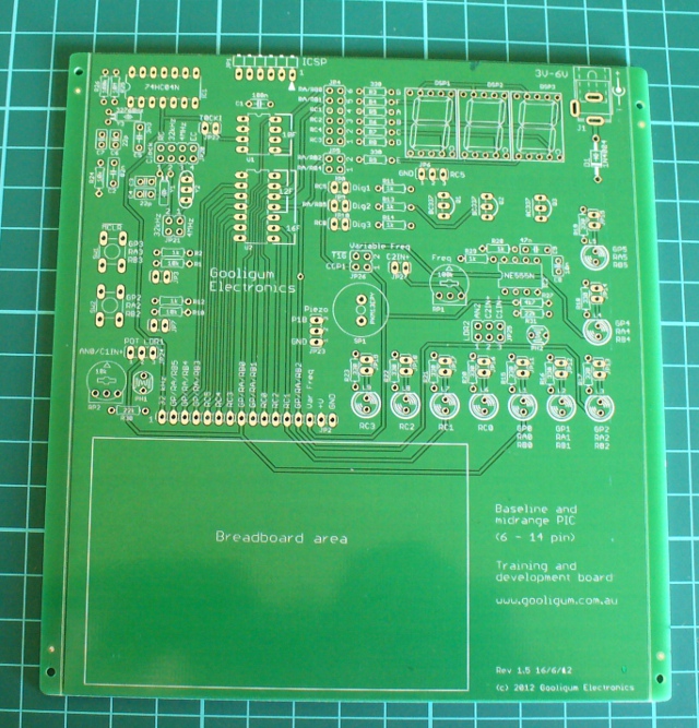
Putting the kit board together wasn’t difficult at all. There isn’t any surface-mount parts to worry about, and the PCB is silk-screened very well:
The rest of the parts are shipped in antistatic bags, appropriately labelled and protected:

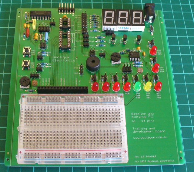
Assembly was straight forward, just start with the low-profile parts and work your way up. The assembly guide is useful to help with component placement. After working at a normal pace, it was ready in just over an hour:
The Hardware
Once assembled (or you’ve opened the packaging) the various sections of the board are obvious and clearly labelled – as they should be for an educational board. You will notice a large amount of jumper headers – they are required to bridge in and out various LEDs, select various input methods and so on. A large amount of jumper shunts is included with the board.
It might appear a little disconcerting at first, but all is revealed and explained as you progress through the lessons. The board has decent rubber feet, and is powered either by the PICkit3 programmer, or a regulated DC power source between 5 and 6V DC, such as from a plug-pack if you want to operate your board away from a PC.
However there is a wide range of functions, input and output devices on the board – and an adjustable oscillator, as shown in the following diagram:

The Lessons
There is some assumed knowledge, which is a reasonable understanding of basic electronics, some computer and mathematical savvy and the C programming language.
You can view the first group of lessons for free on the kit website, and these are included along with the additional lessons in the included CDROM. They’re in .pdf format and easy to read. The CDROM also includes all the code so you don’t have to transcribe it from the lessons. Students start with an absolute introduction to the system, and first learn how to program in assembly language in the first group of tutorials, followed by C in the second set.
This is great as you learn about the microcontroller itself, and basically start from the bottom. Although it’s no secret I enjoy using the Arduino system – it really does hide a lot of the actual hardware knowledge away from the end user which won’t be learned. With David’s system – you will learn.
If you scroll down to the bottom of this page, you can review the tutorial summaries. Finally here’s a quick demonstration of the 7-segment displays in action:
Where to from here?
Once you run through all the tutorials, and feel confident with your knowledge, the world of Microchip PIC will be open to you. Plus you now have a great development board for prototyping with 6 to 14-pin PIC microcontrollers. Don’t forget all the pins are brought out to the row of sockets next to the solderless breadboard, so general prototyping is a breeze.
Conclusion
For those who have mastered basic electronics, and have some C or C-like programming experience from using other development environments or PCs – this package is perfect for getting started with the Microchip PIC environment. Plus you’ll learn about assembly language – which is a good thing. I genuinely recommend this to anyone who wants to learn about PIC and/or move into more advanced microcontroller work. And as the entire package is cheaper than some books – you can’t go wrong. The training course is available directly from the Gooligum website.

Disclaimer - The Baseline and Mid-Range PIC Training Course and Development Board was a promotional consideration from Gooligum Electronics.
In the meanwhile have fun and keep checking into tronixstuff.com. Why not follow things on twitter, Google+, subscribe for email updates or RSS using the links on the right-hand column? And join our friendly Google Group – dedicated to the projects and related items on this website. Sign up – it’s free, helpful to each other – and we can all learn something.

Introduction
[Updated 18/06/2013]
There are many types of microcontrollers on the market, and it would be fair to say one of the two most popular types is the Microchip PIC series. The PICs are great as there is a huge range of microcontrollers available across a broad range of prices. However learning how to get started with the PIC platform isn’t exactly simple. Not that we expect it to be, however a soft start is always better. There are some older books, however they can cost more than $100 – and are generally outdated. So where do you start?
It is with this problem in mind that led fellow Australian David Meiklejohn to develop and offer his PIC Training Course and Development Board to the marketplace via his company Gooligum Electronics.
In his words:
There is plenty of material available on PICs, which can make it daunting to get started. And some of the available material is dated, originally developed before modern “flash” PICs were available, or based on older devices that are no longer the best choice for new designs. Our approach is to introduce PIC programming and design in easy stages, based on a solid grounding in theory, creating a set of building blocks and techniques and giving you the confidence to draw on as we move up to more complex designs.
So in this article we’ll examine David’s course package. First of all, let’s look at the development board and inclusions. Almost everything you will need to complete all the lessons is included in the package, including the following PIC microcontrollers:
You can choose to purchase the board in kit form or pre-assembled. If you enjoy soldering, save the money and get the kit – it’s simple to assemble and a nice way to spend a few hours with a soldering iron.
Although the board includes all the electronic components and PICs – you will need are a computer capable of running Microchip MPLAB software, a Microchip PICkit3 (or -2) programming device and an IC extractor. If you’re building the kit, a typical soldering iron and so on will be required. Being the ultra-paranoid type, I bought a couple extra of each PIC to have as spares, however none were damaged in my experimenting. Just use common-sense when handling the PICs and you will be fine.
Assembly
Putting the kit board together wasn’t difficult at all. There isn’t any surface-mount parts to worry about, and the PCB is silk-screened very well:

The rest of the parts are shipped in antistatic bags, appropriately labelled and protected:

Assembly was straight forward, just start with the low-profile parts and work your way up. The assembly guide is useful to help with component placement. After working at a normal pace, it was ready in just over an hour:

The Hardware
Once assembled (or you’ve opened the packaging) the various sections of the board are obvious and clearly labelled – as they should be for an educational board. You will notice a large amount of jumper headers – they are required to bridge in and out various LEDs, select various input methods and so on. A large amount of jumper shunts is included with the board.
It might appear a little disconcerting at first, but all is revealed and explained as you progress through the lessons. The board has decent rubber feet, and is powered either by the PICkit3 programmer, or a regulated DC power source between 5 and 6V DC, such as from a plug-pack if you want to operate your board away from a PC.
However there is a wide range of functions, input and output devices on the board – and an adjustable oscillator, as shown in the following diagram:

The Lessons
There is some assumed knowledge, which is a reasonable understanding of basic electronics, some computer and mathematical savvy and the C programming language.
You can view the first group of lessons for free on the kit website, and these are included along with the additional lessons in the included CDROM. They’re in .pdf format and easy to read. The CDROM also includes all the code so you don’t have to transcribe it from the lessons. Students start with an absolute introduction to the system, and first learn how to program in assembly language in the first group of tutorials, followed by C in the second set.
This is great as you learn about the microcontroller itself, and basically start from the bottom. Although it’s no secret I enjoy using the Arduino system – it really does hide a lot of the actual hardware knowledge away from the end user which won’t be learned. With David’s system – you will learn.
If you scroll down to the bottom of this page, you can review the tutorial summaries. Finally here’s a quick demonstration of the 7-segment displays in action:
Update – 18/06/2013
David has continued publishing more tutorials for his customers every few months – including such topics as the EEPROM and pulse-width modulation. As part of the expanded lessons you can also get a pack which allows experimenting with electric motors that includes a small DC motor, the TI SN75441 h-bridge IC, N-channel and P-channel MOSFETS and more:

So after the initial purchase, you won’t be left on your own. Kudos to David for continuing to support and develop more material for his customers.
Where to from here?
Once you run through all the tutorials, and feel confident with your knowledge, the world of Microchip PIC will be open to you. Plus you now have a great development board for prototyping with 6 to 14-pin PIC microcontrollers. Don’t forget all the pins are brought out to the row of sockets next to the solderless breadboard, so general prototyping is a breeze.
Conclusion
For those who have mastered basic electronics, and have some C or C-like programming experience from using other development environments or PCs – this package is perfect for getting started with the Microchip PIC environment. Plus you’ll learn about assembly language – which is a good thing. I genuinely recommend this to anyone who wants to learn about PIC and/or move into more advanced microcontroller work. And as the entire package is cheaper than some books – you can’t go wrong. The training course is available directly from the Gooligum website.
Disclaimer - The Baseline and Mid-Range PIC Training Course and Development Board was a promotional consideration from Gooligum Electronics.
In the meanwhile have fun and keep checking into tronixstuff.com. Why not follow things on twitter, Google+, subscribe for email updates or RSS using the links on the right-hand column? And join our friendly Google Group – dedicated to the projects and related items on this website. Sign up – it’s free, helpful to each other – and we can all learn something.
The post Review: Gooligum Electronics PIC Training Course and Development Board appeared first on tronixstuff.

The Arduino IDE is extremely similar to C++, but judging from the sketches you can find on the Internet, you’d never know it. Simpler Arduino projects can make do with just toggling IO pins, reading values, and sending serial data between two points. More complex builds fall into the category of real software development, and this is where the standard Arduino IDE falls miserably short.
[Andy] saw this lack of proper libraries for more complicated pieces of software as a terrible situation and decided to do something about it. He ported the SGI Standard Template Library to bring all those fun algorithms and data structures to any AVR chip, including the Arduino.
Going over what’s included in [Andy]‘s port reads just like a syllabus for an object-oriented programming class. Stacks, queues, and lists make the cut, as do strings and vectors. Also included is just about everything in the and headers along with a few Arduino-oriented additions like a hardware serial and liquid crystal streams.
With all these objects floating around, [Andy] says it will make an impact on Flash and SRAM usage in an AVR. Still, with all the hullabaloo over faster and larger ARM micros, it’s nice to see the classic 8-bit microcontroller becoming a bit more refined.

Planet Arduino is, or at the moment is wishing to become, an aggregation of public weblogs from around the world written by people who develop, play, think on Arduino platform and his son. The opinions expressed in those weblogs and hence this aggregation are those of the original authors. Entries on this page are owned by their authors. We do not edit, endorse or vouch for the contents of individual posts. For more information about Arduino please visit www.arduino.cc
You are currently browsing the archives for the C category.
 Arduino Blog Make Magazine Blog Hackaday Electronics-Lab Noel Portugal CNX-Software Matthew Rollings Chris Debenham Techatronic Giasone John Boxall Arduino++ Adafruit Blog EngineeringException Mamaus's Blog Tinker Hobby Bits and Pieces Wayne and Layne NerdyTechy Liudr's Blog Steve Marple b7arduino Chipwired Embedded-Lab