Updated 27/02/2013
Introduction
After much waiting the Arduino Due has been released, so let’s check it out. We’ll run through the specifications and some areas of interest, see what’s different, some random notes – then try out some of the new features. Before moving forward note that it might look the same - the Due is not a drop-in replacement for older boards – even the Mega2560. It’s different.

First announced in late 2011, the Due is the Arduino team’s first board with a 32-bit processor – the Atmel SAM3X8E ARM Cortex-M3 CPU. With an 84 Mhz CPU speed and a host of interfaces and I/O, this promises to be the fastest and most functional Arduino board ever. According to the official Arduino press release:
Arduino Due is ideal for those who want to build projects that require high computing power such as the remotely-controlled drones that, in order to fly, need to process a lot of sensor data per second.
Arduino Due gives students the opportunity to learn the inner workings of the ARM processor in a cheaper and much simpler way than before.
To Scientific projects, which need to acquire data quickly and accurately, Arduino Due provides a platform to create open source tools that are much more advanced than those available now.
The new platform enables the open source digital fabrication community (3d Printers, Laser cutters, CNC milling machines) to achieve higher resolutions and faster speed with fewer components than in the past.
Sounds good – and the Due has been a long time coming, so let’s hope it is worth the wait. The SAM3X CPU holds a lot of promise for more complex projects that weren’t possible with previous ATmega CPUs, so this can be only a good thing.
Specifications
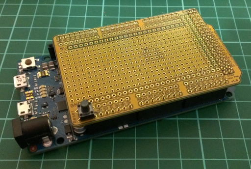
First of all, here’s the Due in detail – top and bottom (click to enlarge):


You can use Mega-sized protoshields without any problem (however older shields may miss out on the upper I2C pins) – they’ll physically fit in … however their contents will be a different story:
The specifications of the Due are as follows (from Arduino website):
| Microcontroller |
|
AT91SAM3X8E |
| Operating Voltage |
|
3.3V |
| Input Voltage (recommended) |
|
7-12V |
| Input Voltage (limits) |
|
6-20V |
| Digital I/O Pins |
|
54 (of which 12 provide PWM output) |
| Analog Input Pins |
|
12 |
| Analog Outputs Pins |
|
2 (DAC) |
| Total DC Output Current on all I/O lines |
|
130 mA |
| DC Current for 3.3V Pin |
|
800 mA |
| DC Current for 5V Pin |
|
800 mA |
| Flash Memory |
|
512 KB all available for the user applications |
| SRAM |
|
96 KB (two banks: 64KB and 32KB) |
| Clock Speed |
|
84 MHz |
Right away a few things should stand out – the first being the operating voltage – 3.3V. That means all your I/O needs to work with 3.3V – not 5V. Don’t feed 5V logic line into a digital input pin and hope it will work – you’ll damage the board. Instead, get yourself some logic level converters. However there is an IOREF pin like other Arduino boards which intelligent shields can read to determine the board voltage. The total output current for all I/O lines is also 130 mA … so no more sourcing 20mA from a digital ouput for those bright LEDs.
The power regulator for 5V has been changed from linear to switching – so no more directly inserting 5V into the 5V pin. However the 3.3V is through an LDO from 5v.
Each digital I/O pin can source 3 or 15 mA – or sink 6 or 9 mA … depending on the pin. High-current pins are CAN-TX, digital 1, 3~12, 23~51, and SDA1. The rest are low current. And there’s still an LED on digital 13. You will need to redesign any existing projects or shields if moving to the Due.
The analogue inputs now have a greater resolution – 12-bits. That means it can return a value of 0~4095 representing 0~3.3V DC. To activate this higher resolution you need to use the function analogReadResolution(12).
Memory – there isn’t any EEPROM in the SAM3X – so you’ll need external EEPROMs to take care of more permanent storage. However there’s 512 KB of flash memory for sketches – which is huge. You have to see it to believe it:
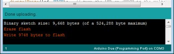
Excellent. A new feature is the onboard erase button. Press it for three seconds and it wipes out the sketch. The traditional serial line is still digital 0/1 – which connect to the USB controller chip.
Hardware serial – there’s four serial lines. Pulse-width modulation (PWM) is still 8-bit and on digital pins 2~13.
The SPI bus is on the ICSP header pins to the right of the microcontroller – so existing shields that use SPI will need to be modified – or experiment with a LeoShield:
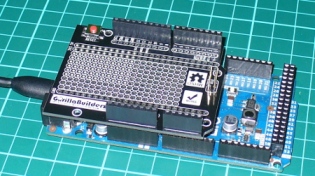
You can also use the extended SPI function of the SAM3X which allow the use of digital pins 4, 10 or 52 for CS (chip select).
The SAM3X supports the automtive CAN bus, and the pins have been brought out onto the stacked header connectors – however this isn’t supported yet in the IDE.
There are two I2C buses – located on digital 20/21 and the second is next to AREF just like on the Leonardo.
There’s a 10-pin JTAG mini-header on the Due, debug pins and a second ICSP for the ATmega16U2 which takes care of USB. Speaking of USB – there’s two microUSB sockets. One is for regular programming via the Arduino IDE and the USB interface, the other is a direct native USB programming port direct to the SAM3X.
The SAM3X natively supports Ethernet, but this hasn’t been implemented on the hardware side for the Due. However some people in the Arduino forum might have a way around that.
Using the Due
First of all – at the time of writing – you need to install Arduino IDE v1.5.1 release 2 – a beta version. Windows users – don’t forget the USB drivers. As always, backup your existing installation and sketch files somewhere safe – and you can run more than one IDE on the same machine.
When it comes time to upload your sketches, plug the USB cable into the lower socket on the Due – and select Arduino Due (Programming Port) from the Tools>Board menu in the IDE.
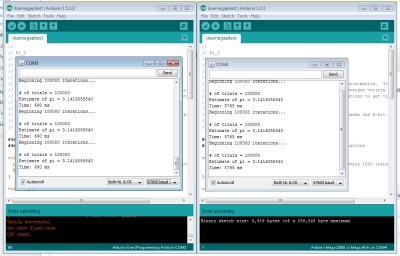
Let’s upload a sketch now (download) – written by Steve Curd from the Arduino forum. It calculates Newton Approximation for pi using an infinite series. As you can see from the results below, the Due is much faster (690 ms) than the Mega2560 (5765 ms). Click the image to enlarge:
Next, let’s give the digital-to-analogue converters a test. Finally we have two, real, 12-bit DACs with the output pins being … DAC0 and DAC1. No more mucking about with external R-C filters to get some audio happening. These pins provides true analogue outputs which is controlled by the analogWrite() function. To use them is very simple – consider the following example sketch which creates a triangle wave:
void setup()
{
 analogWriteResolution(12); // 12-bit!
}
void loop()
{
 for(int x=0; x<4096; x++)
 {
 analogWrite(DAC0, x); // use DAC1 for ... DAC1
 }
 for(int x=4095; x>=0; --x)
 {
 analogWrite(DAC0, x);
 }
}

And the results from the DSO (click image to enlarge):
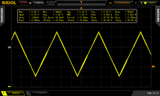
This opens up all sorts of audio possibilities. With appropriate wavetable data saved in memory you could create various effects. However the DAC doesn’t give a full 0~3.3V output – instead it’s 1/6 to 5/6 of the Aref voltage. With the IDE there are example sketches that can play a .wav file from an SDcard – however I’d still be more inclined to use an external shield for that. Nevertheless for more information, have a look at the Audio library. Furthermore, take heed of the user experiences noted in the Arduino forum – it’s very easy to destroy your DAC outputs. In the future we look forward to experimenting further with the Due – so stay tuned.
Getting a Due
Good luck … at the time of writing – the Dues seem to be very thin on the ground. This may partly be due to the limited availability of the Atmel SAM3X8E. My contacts in various suppliers say volumes are quite limited.
Quality
I really hope this is a rare event, however one of the Dues received had the following fault in manufacturing:

One side of the crystal capacitor wasn’t in contact with the PCB. However this was a simple fix. How the QC people missed this … I don’t know. However I’ve seen a few Arduinos of various types, and this error is not indicative of the general quality of Arduino products.
Where to from here?
Visit the official Arduino Due page, the Due discussion section of the Arduino forum, and check out the reference guide for changes to functions that are affected by the different hardware.
Conclusion
Well that’s my first take on the Due – powerful and different. You will need to redesign existing projects, or build new projects around it. And a lot of stuff on the software side is still in beta. So review the Due forum before making any decisions. With that in mind – from a hardware perspective – it’s a great step-up from the Mega2560.
So if you’re interested – get one and take it for a spin, it won’t disappoint. The software will mature over time which will make life easier as well. If you have any questions (apart from Arduino vs. Raspberry Pi) leave a comment and we’ll look into it.

Have fun and keep checking into tronixstuff.com. Why not follow things on twitter, Google+, subscribe for email updates or RSS using the links on the right-hand column, or join our Google Group – dedicated to the projects and related items on this website. Sign up – it’s free, helpful to each other – and we can all learn something.