We are finally ready to release create.arduino.cc, the Arduino platform that will provide the community with a more modern and flexible tool to write code, a more integrated way of accessing content and learning while doing.
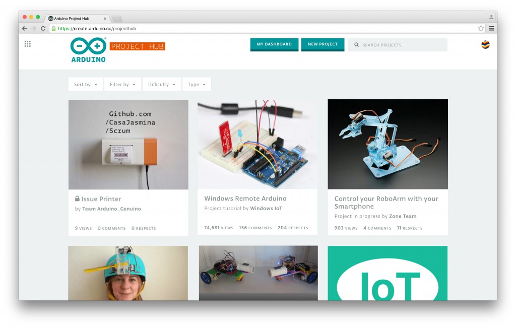
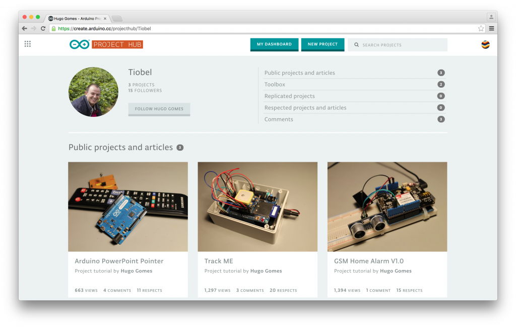
While we are still busy refining the web-based Editor (IDE) based on the feedback of the current beta-testing program, we are really excited to launch Arduino Project Hub, our tutorial platform powered by hackster.io. We cannot wait to see all the projects made with Arduino and Genuino boards that you will submit! Comment on the tutorials you are curious about, and ‘Respect’ the ones you like the most. We will feature the best projects on the Arduino Blog!
Within create.arduino.cc you will be also able to access a new website focused on Internet of Things. Arduino IoT collects inspiring tutorials, and provides guidance for anyone who wants to get started tinkering with the Internet of Things. Most importantly it presents the “Arduino IoT Manifesto”, an important statement that will guide the development of our IoT products and tools in the coming years, and that we hope will be adopted by a larger network of people and industries. We propose these three principles for the future of this burgeoning industry: Open, Sustainable and Fair!
As usual if you encounter any issue, or you have an idea you want to share, please let us know on the Arduino Forum, we’d love to hear your feedback!
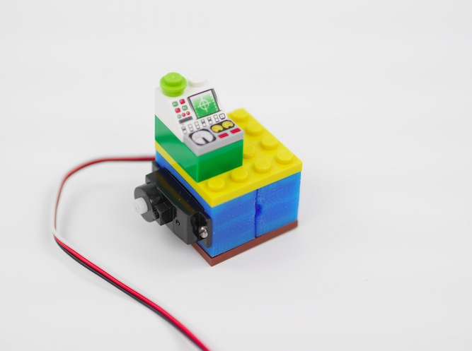
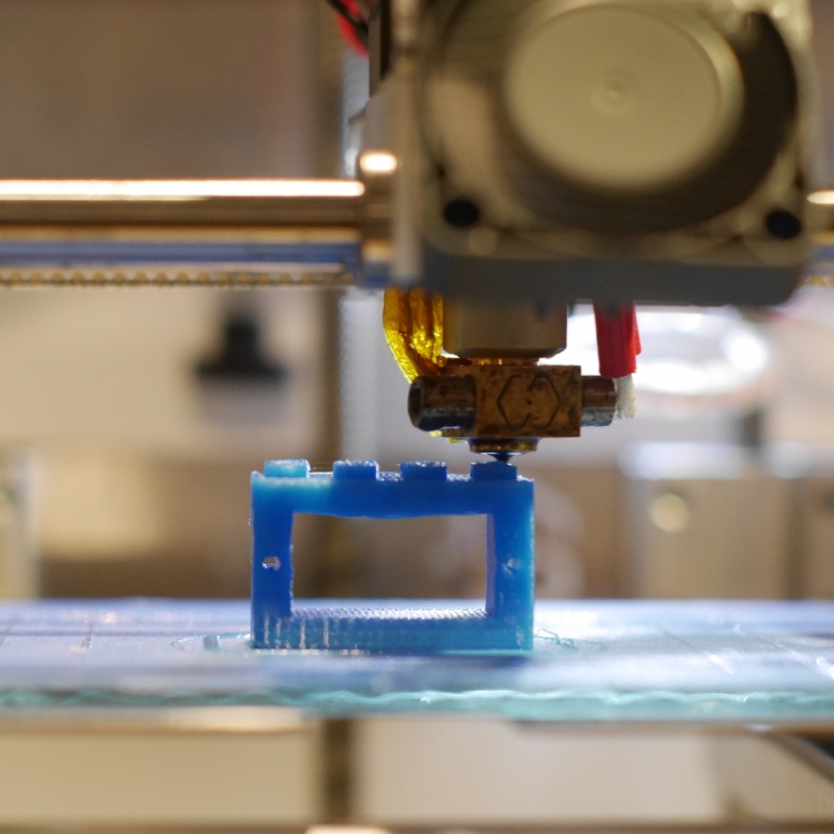
This week we are presenting you a new tutorial on 3d printing of Lego-compatible pieces with Materia 101. Kristoffer designed a brick with the parametric 3d modeler FreeCAD that can hold a small servo. Following the 10-step instructions you can easily add wheels to robots built in LEGO and use specific servos with different sizes.
Using a 3d printer means playing with some hardware but especially some softwares. In the tutorial of this week, the fourth tutorial of our series , Kris is going to introduce you how to work with Slic3r, a G-Code generator for 3d printers and basically a tool you need to convert a digital 3D model into printing instructions for your 3D printer. Slic3r is an open source software able to cut the model into horizontal slices (layers), generates toolpaths to fill them and calculates the amount of material to be extruded so that you can reach good results.
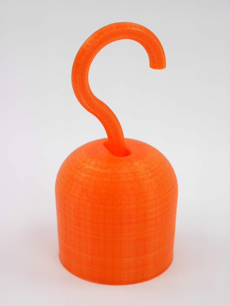
The object you’ll be able to print with your Materia 101 is a pirate hook !
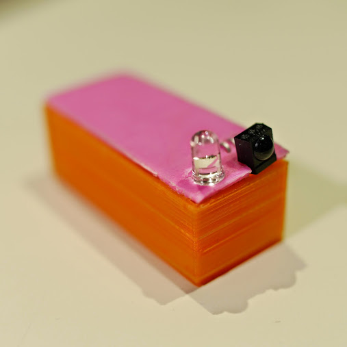
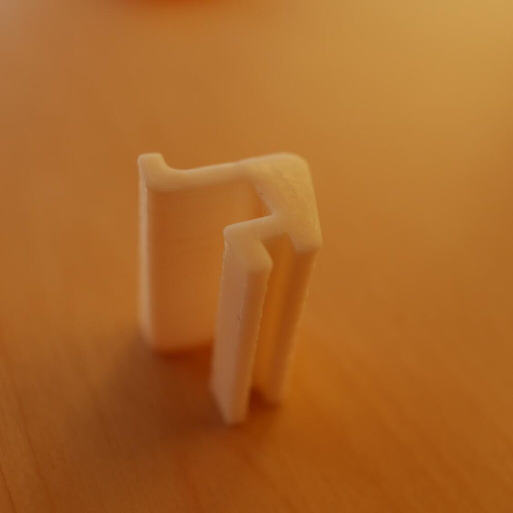
One of the pleasures of watching TV depends on the use of a remote control that allows you to change channels from where you are. In the tutorial of this week, Kristoffer made an add-on to a previous lesson teaching us how to control a computer with a remote control like the one of your TV using Arduino Micro, IR-sensor. The add-on is a custom and colourful 3d-printed case created with Freecad and Materia 101.
When you become a happy owner of a Materia 101 3d printer, the first days are really important to start experimenting with the right attitude. Understanding quickly how to get what you want from it means becoming aware of the potential applications of the 3d printing technology in your environment.
Take a look at the second tutorial focused on fixing things at home: “Making something useful” tutorial shows you how to start from a need, to design and print a solution. It feels great to be able to fix what’s broken!
Interested in getting in touch and showing your experiments? Join Kristoffer on the Arduino forum and give us your feedback.
Next week we are going to post a tutorial on how to create 3d-printed cases for Arduino boards. Stay tuned.
Agy used for the first time Lilypad Arduino and LEDs on a textile project called Blinky Bike Bag, combining her expertise in fabric hacking with electronics:
The bike bag is made from umbrella material to make it waterproof, and I made it with safety features using the Lilypad light sensor and LEDs. My husband always forgets his reflectors but with the bikebag always being on the bike, he’ll have no excuse not to be a safe cyclist!
A lot has happened since our last article was published and to celebrate the continuance of bildr we’ll be playing with the MQ-3 Alcohol Gas Sensor. Coupled with the SparkFun Gas Sensor Breakout Board, connecting the MQ-3 to your Arduino is a breeze.
The MQ-3 is a heater-driven alcohol sensor that outputs an analog signal (usually interpreted somewhere between 150 and 1023 depending on how long you let the sensor warm up), which through the use of your Arduino code and calibration, can be interpreted for whatever use you need.
Putting The Pieces Together
When attaching your MQ-3 to the SparkFun Breakout Board, it should be noted that it doesn’t matter which way the MQ-3 alcohol sensor is pressed in. Both the A pins are electronically the same as well as the B pins. The center pins on both sides are the heater element pins. Since the circuit will be running on +5V DC it doesn’t matter which way the sensor is soldered to the board. As long as you have the SparkFun logos and pin labels facing downward, so you can still see them when the sensor is flipped over, you are good to go!
Note: Again, the MQ-3 is heater-driven so be aware that the sensor will become warm and may even emit a smell at first. This is completely normal.
Calibration: If you take your time, you can find out what values equate to specific percentages or even blood alcohol concentration in the case of a breathalyzer. You will of course need to calibrate your MQ-3 based on your specific Arduino code since sensor readings will vary. Although I can’t help with your specific calibration scenario, the best advice I can give you is to use several isopropyl alcohol bottles at different percentages for your testing. Do NOT get the sensor wet with alcohol! Simply squeeze to breathe the vapors of the alcohol into the sensor and take your readings.
Code
The Arduino code for this is very simple if you just want to view the raw data.
int mq3_analogPin = A0;// connected to the output pin of MQ3 void setup(){Serial.begin(9600);// open serial at 9600 bps}void loop(){// give ample warmup time for readings to stabilizeint mq3_value =analogRead(mq3_analogPin);Serial.println(mq3_value);delay(100);//Just here to slow down the output.}
Unless otherwise stated, this code is released under the MIT License – Please use, change and share it.
During Maker Faire Rome, at the beginning of October, RS Components together with Massimo Banzi and David Cuartielles, unveiled the release of other five exclusive video tutorials introducing the Arduino Robot and exploring various characteristics of this new open-source hardware on wheels.
The series of five 10 minute videos (English language, with subtitled versions available in French, German, Simplified Chinese, Traditional Chinese and Japanese!) follows an instructive and entertaining journey through the use of the Robot, and shows Massimo Banzi, along with Arduino co-founder David Cuartielles and Interaction Designer Xun Yang, having fun with some example projects:
- Introduction to Arduino Robot – how to unbox, mount, and use the Arduino IDE to program the Robot
- LOGO and Remote Control your Robot – where to find code examples on the IDE, and how to control the Robot using a universal TV remote
- Avoid Obstacles, Create Strategies – use different technologies to detect distance from the Robot to objects in the room
- Following Lines, Going to the Rescue – how to follow lines using the IR-array sensor on the motor board
- Images and Sounds – how to use the screen and play sound on the Robot’s speaker
Massimo Banzi said, “I am very pleased to announce Arduino’s partnership with RS at the Maker Faire. We have worked together to create five exclusive video tutorials, which feature the new Arduino Robot. David Cuartielles and Xun Yang joined me to cover everything from the Arduino Robot essentials to more challenging programming. This has been a very exciting time for Arduino, and the team is looking forward to learning how followers will be using the Robot.”
“These videos from the makers of Arduino give a simple, step-by-step guide to using and developing projects with the Robot,” said Glenn Jarrett, Global Head of Product Marketing, RS Components. “The informative yet light-hearted content will appeal equally to existing Arduino enthusiasts and to anyone dipping their toes into the world of computer programming for the first time.”
Use the Maxim MAX7219 LED display driver with Arduino in Chapter 56 of our Arduino Tutorials. The first chapter is here, the complete series is detailed here.
Introduction
Sooner or later Arduino enthusiasts and beginners alike will come across the MAX7219 IC. And for good reason, it’s a simple and somewhat inexpensive method of controlling 64 LEDs in either matrix or numeric display form. Furthermore they can be chained together to control two or more units for even more LEDs. Overall – they’re a lot of fun and can also be quite useful, so let’s get started.
Here’s an example of a MAX7219 and another IC which is a functional equivalent, the AS1107 from Austria Microsystems. You might not see the AS1107 around much, but it can be cheaper – so don’t be afraid to use that instead:
When shopping for MAX7219s you may notice the wild price fluctuations between various sellers. We’ve researched that and have a separate article for your consideration.
At first glance you may think that it takes a lot of real estate, but it saves some as well. As mentioned earlier, the MAX7219 can completely control 64 individual LEDs – including maintaining equal brightness, and allowing you to adjust the brightness of the LEDs either with hardware or software (or both). It can refresh the LEDs at around 800 Hz, so no more flickering, uneven LED displays.
You can even switch the display off for power saving mode, and still send it data while it is off. And another good thing – when powered up, it keeps the LEDs off, so no wacky displays for the first seconds of operation. For more technical information, here is the data sheet: MAX7219.pdf. Now to put it to work for us – we’ll demonstrate using one or more 8 x 8 LED matrix displays, as well as 8 digits of 7-segment LED numbers.
Before continuing, download and install the LedControl Arduino library as it is essential for using the MAX7219.
Controlling LED matrix displays with the MAX7219
First of all, let’s examine the hardware side of things. Here is the pinout diagram for the MAX7219:
The MAX7219 drives eight LEDs at a time, and by rapidly switching banks of eight your eyes don’t see the changes. Wiring up a matrix is very simple – if you have a common matrix with the following schematic:
connect the MAX7219 pins labelled DP, A~F to the row pins respectively, and the MAX7219 pins labelled DIG0~7 to the column pins respectively. A total example circuit with the above matrix is as follows:
The circuit is quite straight forward, except we have a resistor between 5V and MAX7219 pin 18. The MAX7219 is a constant-current LED driver, and the value of the resistor is used to set the current flow to the LEDs. Have a look at table eleven on page eleven of the data sheet:
You’ll need to know the voltage and forward current for your LED matrix or numeric display, then match the value on the table. E.g. if you have a 2V 20 mA LED, your resistor value will be 28kΩ (the values are in kΩ). Finally, the MAX7219 serial in, load and clock pins will go to Arduino digital pins which are specified in the sketch. We’ll get to that in the moment, but before that let’s return to the matrix modules.
In the last few months there has been a proliferation of inexpensive kits that contain a MAX7219 or equivalent, and an LED matrix. These are great for experimenting with and can save you a lot of work – some examples of which are shown below:
At the top is an example from ebay, and the pair on the bottom are the units from a recent kit review. We’ll use these for our demonstrations as well.
Now for the sketch. You need the following two lines at the beginning of the sketch:
The first pulls in the library, and the second line sets up an instance to control. The four parameters are as follows:
the digital pin connected to pin 1 of the MAX7219 (“data in”)
the digital pin connected to pin 13 of the MAX7219 (“CLK or clock”)
the digital pin connected to pin 12 of the MAX7219 (“LOAD”)
The number of MAX7219s connected.
If you have more than one MAX7219, connect the DOUT (“data out”) pin of the first MAX7219 to pin 1 of the second, and so on. However the CLK and LOAD pins are all connected in parallel and then back to the Arduino.
Next, two more vital functions that you’d normally put in void setup():
lc.shutdown(0,false);
lc.setIntensity(0,8);
The first line above turns the LEDs connected to the MAX7219 on. If you set TRUE, you can send data to the MAX7219 but the LEDs will stay off. The second line adjusts the brightness of the LEDs in sixteen stages. For both of those functions (and all others from the LedControl) the first parameter is the number of the MAX7219 connected. If you have one, the parameter is zero… for two MAX7219s, it’s 1 and so on.
Finally, to turn an individual LED in the matrix on or off, use:
lc.setLed(0,col,row,true);
which turns on an LED positioned at col, row connected to MAX7219 #1. Change TRUE to FALSE to turn it off. These functions are demonstrated in the following sketch:
#include "LedControl.h" //  need the library
LedControl lc=LedControl(12,11,10,1); //

// pin 12 is connected to the MAX7219 pin 1
// pin 11 is connected to the CLK pin 13
// pin 10 is connected to LOAD pin 12
// 1 as we are only using 1 MAX7219

void setup()
{
  // the zero refers to the MAX7219 number, it is zero for 1 chip
  lc.shutdown(0,false);// turn off power saving, enables display
  lc.setIntensity(0,8);// sets brightness (0~15 possible values)
  lc.clearDisplay(0);// clear screen
}
void loop()
{
  for (int row=0; row<8; row++)
  {
    for (int col=0; col<8; col++)
    {
      lc.setLed(0,col,row,true); // turns on LED at col, row
      delay(25);
    }
  }

  for (int row=0; row<8; row++)
  {
    for (int col=0; col<8; col++)
    {
      lc.setLed(0,col,row,false); // turns off LED at col, row
      delay(25);
    }
  }
}
And a quick video of the results:
How about controlling two MAX7219s? Or more? The hardware modifications are easy – connect the serial data out pin from your first MAX7219 to the data in pin on the second (and so on), and the LOAD and CLOCK pins from the first MAX7219 connect to the second (and so on). You will of course still need the 5V, GND, resistor, capacitors etc. for the second and subsequent MAX7219.
You will also need to make a few changes in your sketch. The first is to tell it how many MAX7219s you’re using in the following line:
LedControl lc=LedControl(12,11,10,X);
by replacing X with the quantity. Then whenever you’re using a MAX7219 function, replace the (previously used) zero with the number of the MAX7219 you wish to address. They are numbered from zero upwards, with the MAX7219 directly connected to the Arduino as unit zero, then one etc. To demonstrate this, we replicate the previous example but with two MAX7219s:
#include "LedControl.h" //  need the library
LedControl lc=LedControl(12,11,10,2); //

// pin 12 is connected to the MAX7219 pin 1
// pin 11 is connected to the CLK pin 13
// pin 10 is connected to LOAD pin 12
// 1 as we are only using 1 MAX7219

void setup()
{
  lc.shutdown(0,false);// turn off power saving, enables display
  lc.setIntensity(0,8);// sets brightness (0~15 possible values)
  lc.clearDisplay(0);// clear screen

  lc.shutdown(1,false);// turn off power saving, enables display
  lc.setIntensity(1,8);// sets brightness (0~15 possible values)
  lc.clearDisplay(1);// clear screen
}

void loop()
{
  for (int row=0; row<8; row++)
  {
    for (int col=0; col<8; col++)
    {
      lc.setLed(0,col,row,true); // turns on LED at col, row
      lc.setLed(1,col,row,false); // turns on LED at col, row
      delay(25);
    }
  }

  for (int row=0; row<8; row++)
  {
    for (int col=0; col<8; col++)
    {
      lc.setLed(0,col,row,false); // turns off LED at col, row
      lc.setLed(1,col,row,true); // turns on LED at col, row
      delay(25);
    }
  }
}
And again, a quick demonstration:
Another fun use of the MAX7219 and LED matrices is to display scrolling text. For the case of simplicity we’ll use the LedControl library and the two LED matrix modules from the previous examples.
First our example sketch – it is quite long however most of this is due to defining the characters for each letter of the alphabet and so on. We’ll explain it at the other end!
// based on an orginal sketch by Arduino forum member "danigom"
// http://forum.arduino.cc/index.php?action=profile;u=188950

#include <avr/pgmspace.h>
#include <LedControl.h>

const int numDevices = 2;      // number of MAX7219s used
const long scrollDelay = 75;   // adjust scrolling speed

unsigned long bufferLong [14] = {0};

LedControl lc=LedControl(12,11,10,numDevices);

prog_uchar scrollText[] PROGMEM ={
    "  THE QUICK BROWN FOX JUMPED OVER THE LAZY DOG 1234567890 the quick brown fox jumped over the lazy dog   \0"};

void setup(){
    for (int x=0; x<numDevices; x++){
        lc.shutdown(x,false);       //The MAX72XX is in power-saving mode on startup
        lc.setIntensity(x,8);       // Set the brightness to default value
        lc.clearDisplay(x);         // and clear the display
    }
}

void loop(){
    scrollMessage(scrollText);
    scrollFont();
}

///////////////////////////////////////////////////////////////////////////////////////////////////////////////////

prog_uchar font5x7 [] PROGMEM = {      //Numeric Font Matrix (Arranged as 7x font data + 1x kerning data)
    B00000000,	//Space (Char 0x20)
    B00000000,
    B00000000,
    B00000000,
    B00000000,
    B00000000,
    B00000000,
    6,

    B10000000,	//!
    B10000000,
    B10000000,
    B10000000,
    B00000000,
    B00000000,
    B10000000,
    2,

    B10100000,	//"
    B10100000,
    B10100000,
    B00000000,
    B00000000,
    B00000000,
    B00000000,
    4,

    B01010000,	//#
    B01010000,
    B11111000,
    B01010000,
    B11111000,
    B01010000,
    B01010000,
    6,

    B00100000,	//$
    B01111000,
    B10100000,
    B01110000,
    B00101000,
    B11110000,
    B00100000,
    6,

    B11000000,	//%
    B11001000,
    B00010000,
    B00100000,
    B01000000,
    B10011000,
    B00011000,
    6,

    B01100000,	//&
    B10010000,
    B10100000,
    B01000000,
    B10101000,
    B10010000,
    B01101000,
    6,

    B11000000,	//'
    B01000000,
    B10000000,
    B00000000,
    B00000000,
    B00000000,
    B00000000,
    3,

    B00100000,	//(
    B01000000,
    B10000000,
    B10000000,
    B10000000,
    B01000000,
    B00100000,
    4,

    B10000000,	//)
    B01000000,
    B00100000,
    B00100000,
    B00100000,
    B01000000,
    B10000000,
    4,

    B00000000,	//*
    B00100000,
    B10101000,
    B01110000,
    B10101000,
    B00100000,
    B00000000,
    6,

    B00000000,	//+
    B00100000,
    B00100000,
    B11111000,
    B00100000,
    B00100000,
    B00000000,
    6,

    B00000000,	//,
    B00000000,
    B00000000,
    B00000000,
    B11000000,
    B01000000,
    B10000000,
    3,

    B00000000,	//-
    B00000000,
    B11111000,
    B00000000,
    B00000000,
    B00000000,
    B00000000,
    6,

    B00000000,	//.
    B00000000,
    B00000000,
    B00000000,
    B00000000,
    B11000000,
    B11000000,
    3,

    B00000000,	///
    B00001000,
    B00010000,
    B00100000,
    B01000000,
    B10000000,
    B00000000,
    6,

    B01110000,	//0
    B10001000,
    B10011000,
    B10101000,
    B11001000,
    B10001000,
    B01110000,
    6,

    B01000000,	//1
    B11000000,
    B01000000,
    B01000000,
    B01000000,
    B01000000,
    B11100000,
    4,

    B01110000,	//2
    B10001000,
    B00001000,
    B00010000,
    B00100000,
    B01000000,
    B11111000,
    6,

    B11111000,	//3
    B00010000,
    B00100000,
    B00010000,
    B00001000,
    B10001000,
    B01110000,
    6,

    B00010000,	//4
    B00110000,
    B01010000,
    B10010000,
    B11111000,
    B00010000,
    B00010000,
    6,

    B11111000,	//5
    B10000000,
    B11110000,
    B00001000,
    B00001000,
    B10001000,
    B01110000,
    6,

    B00110000,	//6
    B01000000,
    B10000000,
    B11110000,
    B10001000,
    B10001000,
    B01110000,
    6,

    B11111000,	//7
    B10001000,
    B00001000,
    B00010000,
    B00100000,
    B00100000,
    B00100000,
    6,

    B01110000,	//8
    B10001000,
    B10001000,
    B01110000,
    B10001000,
    B10001000,
    B01110000,
    6,

    B01110000,	//9
    B10001000,
    B10001000,
    B01111000,
    B00001000,
    B00010000,
    B01100000,
    6,

    B00000000,	//:
    B11000000,
    B11000000,
    B00000000,
    B11000000,
    B11000000,
    B00000000,
    3,

    B00000000,	//;
    B11000000,
    B11000000,
    B00000000,
    B11000000,
    B01000000,
    B10000000,
    3,

    B00010000,	//<
    B00100000,
    B01000000,
    B10000000,
    B01000000,
    B00100000,
    B00010000,
    5,

    B00000000,	//=
    B00000000,
    B11111000,
    B00000000,
    B11111000,
    B00000000,
    B00000000,
    6,

    B10000000,	//>
    B01000000,
    B00100000,
    B00010000,
    B00100000,
    B01000000,
    B10000000,
    5,

    B01110000,	//?
    B10001000,
    B00001000,
    B00010000,
    B00100000,
    B00000000,
    B00100000,
    6,

    B01110000,	//@
    B10001000,
    B00001000,
    B01101000,
    B10101000,
    B10101000,
    B01110000,
    6,

    B01110000,	//A
    B10001000,
    B10001000,
    B10001000,
    B11111000,
    B10001000,
    B10001000,
    6,

    B11110000,	//B
    B10001000,
    B10001000,
    B11110000,
    B10001000,
    B10001000,
    B11110000,
    6,

    B01110000,	//C
    B10001000,
    B10000000,
    B10000000,
    B10000000,
    B10001000,
    B01110000,
    6,

    B11100000,	//D
    B10010000,
    B10001000,
    B10001000,
    B10001000,
    B10010000,
    B11100000,
    6,

    B11111000,	//E
    B10000000,
    B10000000,
    B11110000,
    B10000000,
    B10000000,
    B11111000,
    6,

    B11111000,	//F
    B10000000,
    B10000000,
    B11110000,
    B10000000,
    B10000000,
    B10000000,
    6,

    B01110000,	//G
    B10001000,
    B10000000,
    B10111000,
    B10001000,
    B10001000,
    B01111000,
    6,

    B10001000,	//H
    B10001000,
    B10001000,
    B11111000,
    B10001000,
    B10001000,
    B10001000,
    6,

    B11100000,	//I
    B01000000,
    B01000000,
    B01000000,
    B01000000,
    B01000000,
    B11100000,
    4,

    B00111000,	//J
    B00010000,
    B00010000,
    B00010000,
    B00010000,
    B10010000,
    B01100000,
    6,

    B10001000,	//K
    B10010000,
    B10100000,
    B11000000,
    B10100000,
    B10010000,
    B10001000,
    6,

    B10000000,	//L
    B10000000,
    B10000000,
    B10000000,
    B10000000,
    B10000000,
    B11111000,
    6,

    B10001000,	//M
    B11011000,
    B10101000,
    B10101000,
    B10001000,
    B10001000,
    B10001000,
    6,

    B10001000,	//N
    B10001000,
    B11001000,
    B10101000,
    B10011000,
    B10001000,
    B10001000,
    6,

    B01110000,	//O
    B10001000,
    B10001000,
    B10001000,
    B10001000,
    B10001000,
    B01110000,
    6,

    B11110000,	//P
    B10001000,
    B10001000,
    B11110000,
    B10000000,
    B10000000,
    B10000000,
    6,

    B01110000,	//Q
    B10001000,
    B10001000,
    B10001000,
    B10101000,
    B10010000,
    B01101000,
    6,

    B11110000,	//R
    B10001000,
    B10001000,
    B11110000,
    B10100000,
    B10010000,
    B10001000,
    6,

    B01111000,	//S
    B10000000,
    B10000000,
    B01110000,
    B00001000,
    B00001000,
    B11110000,
    6,

    B11111000,	//T
    B00100000,
    B00100000,
    B00100000,
    B00100000,
    B00100000,
    B00100000,
    6,

    B10001000,	//U
    B10001000,
    B10001000,
    B10001000,
    B10001000,
    B10001000,
    B01110000,
    6,

    B10001000,	//V
    B10001000,
    B10001000,
    B10001000,
    B10001000,
    B01010000,
    B00100000,
    6,

    B10001000,	//W
    B10001000,
    B10001000,
    B10101000,
    B10101000,
    B10101000,
    B01010000,
    6,

    B10001000,	//X
    B10001000,
    B01010000,
    B00100000,
    B01010000,
    B10001000,
    B10001000,
    6,

    B10001000,	//Y
    B10001000,
    B10001000,
    B01010000,
    B00100000,
    B00100000,
    B00100000,
    6,

    B11111000,	//Z
    B00001000,
    B00010000,
    B00100000,
    B01000000,
    B10000000,
    B11111000,
    6,

    B11100000,	//[
    B10000000,
    B10000000,
    B10000000,
    B10000000,
    B10000000,
    B11100000,
    4,

    B00000000,	//(Backward Slash)
    B10000000,
    B01000000,
    B00100000,
    B00010000,
    B00001000,
    B00000000,
    6,

    B11100000,	//]
    B00100000,
    B00100000,
    B00100000,
    B00100000,
    B00100000,
    B11100000,
    4,

    B00100000,	//^
    B01010000,
    B10001000,
    B00000000,
    B00000000,
    B00000000,
    B00000000,
    6,

    B00000000,	//_
    B00000000,
    B00000000,
    B00000000,
    B00000000,
    B00000000,
    B11111000,
    6,

    B10000000,	//`
    B01000000,
    B00100000,
    B00000000,
    B00000000,
    B00000000,
    B00000000,
    4,

    B00000000,	//a
    B00000000,
    B01110000,
    B00001000,
    B01111000,
    B10001000,
    B01111000,
    6,

    B10000000,	//b
    B10000000,
    B10110000,
    B11001000,
    B10001000,
    B10001000,
    B11110000,
    6,

    B00000000,	//c
    B00000000,
    B01110000,
    B10001000,
    B10000000,
    B10001000,
    B01110000,
    6,

    B00001000,	//d
    B00001000,
    B01101000,
    B10011000,
    B10001000,
    B10001000,
    B01111000,
    6,

    B00000000,	//e
    B00000000,
    B01110000,
    B10001000,
    B11111000,
    B10000000,
    B01110000,
    6,

    B00110000,	//f
    B01001000,
    B01000000,
    B11100000,
    B01000000,
    B01000000,
    B01000000,
    6,

    B00000000,	//g
    B01111000,
    B10001000,
    B10001000,
    B01111000,
    B00001000,
    B01110000,
    6,

    B10000000,	//h
    B10000000,
    B10110000,
    B11001000,
    B10001000,
    B10001000,
    B10001000,
    6,

    B01000000,	//i
    B00000000,
    B11000000,
    B01000000,
    B01000000,
    B01000000,
    B11100000,
    4,

    B00010000,	//j
    B00000000,
    B00110000,
    B00010000,
    B00010000,
    B10010000,
    B01100000,
    5,

    B10000000,	//k
    B10000000,
    B10010000,
    B10100000,
    B11000000,
    B10100000,
    B10010000,
    5,

    B11000000,	//l
    B01000000,
    B01000000,
    B01000000,
    B01000000,
    B01000000,
    B11100000,
    4,

    B00000000,	//m
    B00000000,
    B11010000,
    B10101000,
    B10101000,
    B10001000,
    B10001000,
    6,

    B00000000,	//n
    B00000000,
    B10110000,
    B11001000,
    B10001000,
    B10001000,
    B10001000,
    6,

    B00000000,	//o
    B00000000,
    B01110000,
    B10001000,
    B10001000,
    B10001000,
    B01110000,
    6,

    B00000000,	//p
    B00000000,
    B11110000,
    B10001000,
    B11110000,
    B10000000,
    B10000000,
    6,

    B00000000,	//q
    B00000000,
    B01101000,
    B10011000,
    B01111000,
    B00001000,
    B00001000,
    6,

    B00000000,	//r
    B00000000,
    B10110000,
    B11001000,
    B10000000,
    B10000000,
    B10000000,
    6,

    B00000000,	//s
    B00000000,
    B01110000,
    B10000000,
    B01110000,
    B00001000,
    B11110000,
    6,

    B01000000,	//t
    B01000000,
    B11100000,
    B01000000,
    B01000000,
    B01001000,
    B00110000,
    6,

    B00000000,	//u
    B00000000,
    B10001000,
    B10001000,
    B10001000,
    B10011000,
    B01101000,
    6,

    B00000000,	//v
    B00000000,
    B10001000,
    B10001000,
    B10001000,
    B01010000,
    B00100000,
    6,

    B00000000,	//w
    B00000000,
    B10001000,
    B10101000,
    B10101000,
    B10101000,
    B01010000,
    6,

    B00000000,	//x
    B00000000,
    B10001000,
    B01010000,
    B00100000,
    B01010000,
    B10001000,
    6,

    B00000000,	//y
    B00000000,
    B10001000,
    B10001000,
    B01111000,
    B00001000,
    B01110000,
    6,

    B00000000,	//z
    B00000000,
    B11111000,
    B00010000,
    B00100000,
    B01000000,
    B11111000,
    6,

    B00100000,	//{
    B01000000,
    B01000000,
    B10000000,
    B01000000,
    B01000000,
    B00100000,
    4,

    B10000000,	//|
    B10000000,
    B10000000,
    B10000000,
    B10000000,
    B10000000,
    B10000000,
    2,

    B10000000,	//}
    B01000000,
    B01000000,
    B00100000,
    B01000000,
    B01000000,
    B10000000,
    4,

    B00000000,	//~
    B00000000,
    B00000000,
    B01101000,
    B10010000,
    B00000000,
    B00000000,
    6,

    B01100000,	// (Char 0x7F)
    B10010000,
    B10010000,
    B01100000,
    B00000000,
    B00000000,
    B00000000,
    5
};

void scrollFont() {
    for (int counter=0x20;counter<0x80;counter++){
        loadBufferLong(counter);
        delay(500);
    }
}

// Scroll Message
void scrollMessage(prog_uchar * messageString) {
    int counter = 0;
    int myChar=0;
    do {
        // read back a char
        myChar =  pgm_read_byte_near(messageString + counter);
        if (myChar != 0){
            loadBufferLong(myChar);
        }
        counter++;
    }
    while (myChar != 0);
}
// Load character into scroll buffer
void loadBufferLong(int ascii){
    if (ascii >= 0x20 && ascii <=0x7f){
        for (int a=0;a<7;a++){                      // Loop 7 times for a 5x7 font
            unsigned long c = pgm_read_byte_near(font5x7 + ((ascii - 0x20) * 8) + a);     // Index into character table to get row data
            unsigned long x = bufferLong [a*2];     // Load current scroll buffer
            x = x | c;                              // OR the new character onto end of current
            bufferLong [a*2] = x;                   // Store in buffer
        }
        byte count = pgm_read_byte_near(font5x7 +((ascii - 0x20) * 8) + 7);     // Index into character table for kerning data
        for (byte x=0; x<count;x++){
            rotateBufferLong();
            printBufferLong();
            delay(scrollDelay);
        }
    }
}
// Rotate the buffer
void rotateBufferLong(){
    for (int a=0;a<7;a++){                      // Loop 7 times for a 5x7 font
        unsigned long x = bufferLong [a*2];     // Get low buffer entry
        byte b = bitRead(x,31);                 // Copy high order bit that gets lost in rotation
        x = x<<1;                               // Rotate left one bit
        bufferLong [a*2] = x;                   // Store new low buffer
        x = bufferLong [a*2+1];                 // Get high buffer entry
        x = x<<1;                               // Rotate left one bit
        bitWrite(x,0,b);                        // Store saved bit
        bufferLong [a*2+1] = x;                 // Store new high buffer
    }
}
// Display Buffer on LED matrix
void printBufferLong(){
  for (int a=0;a<7;a++){                    // Loop 7 times for a 5x7 font
    unsigned long x = bufferLong [a*2+1];   // Get high buffer entry
    byte y = x;                             // Mask off first character
    lc.setRow(3,a,y);                       // Send row to relevent MAX7219 chip
    x = bufferLong [a*2];                   // Get low buffer entry
    y = (x>>24);                            // Mask off second character
    lc.setRow(2,a,y);                       // Send row to relevent MAX7219 chip
    y = (x>>16);                            // Mask off third character
    lc.setRow(1,a,y);                       // Send row to relevent MAX7219 chip
    y = (x>>8);                             // Mask off forth character
    lc.setRow(0,a,y);                       // Send row to relevent MAX7219 chip
  }
}
The pertinent parts are at the top of the sketch – the following line sets the number of MAX7219s in the hardware:
const int numDevices = 2;
The following can be adjusted to change the speed of text scrolling:
const long scrollDelay = 75;
… then place the text to scroll in the following (for example):
prog_uchar scrollText[] PROGMEM ={
    "  THE QUICK BROWN FOX JUMPED OVER THE LAZY DOG 1234567890 the quick brown fox jumped over the lazy dog   \0"};
Finally – to scroll the text on demand, use the following:
scrollMessage(scrollText);
You can then incorporate the code into your own sketches. And a video of the example sketch in action:
Although we used the LedControl library, there are many others out there for scrolling text. One interesting example is Parola – which is incredibly customisable. If you’re looking for a much larger device to scroll text, check out the Freetronics DMD range.
Controlling LED numeric displays with the MAX7219
Using the MAX7219 and the LedControl library you can also drive numeric LED displays – up to eight digits from the one MAX7219. This gives you the ability to make various numeric displays that are clear to read and easy to control. When shopping around for numeric LED displays, make sure you have the common-cathode type.
Connecting numeric displays is quite simple, consider the following schematic which should appear familiar by now:
The schematic shows the connections for modules or groups of up to eight digits. Each digit’s A~F and dp (decimal point) anodes connect together to the MAX7219, and each digit’s cathode connects in order as well. The MAX7219 will display each digit in turn by using one cathode at a time. Of course if you want more than eight digits, connect another MAX7219 just as we did with the LED matrices previously.
The required code in the sketch is identical to the LED matrix code, however to display individual digits we use:
lc.setDigit(A, B, C, D);
where A is the MAX7219 we’re using, B is the digit to use (from a possible 0 to 7), C is the digit to display (0~9… if you use 10~15 it will display A~F respectively) and D is false/true (digit on or off). You can also send basic characters such as a dash “-” with the following:
lc.setChar(A, B,'-',false);
Now let’s put together an example of eight digits:
#include "LedControl.h" //  need the library
LedControl lc=LedControl(12,11,10,1); // lc is our object
// pin 12 is connected to the MAX7219 pin 1
// pin 11 is connected to the CLK pin 13
// pin 10 is connected to LOAD pin 12
// 1 as we are only using 1 MAX7219
void setup()
{
  // the zero refers to the MAX7219 number, it is zero for 1 chip
  lc.shutdown(0,false);// turn off power saving, enables display
  lc.setIntensity(0,8);// sets brightness (0~15 possible values)
  lc.clearDisplay(0);// clear screen
}
void loop()
{
  for (int a=0; a<8; a++)
  {
    lc.setDigit(0,a,a,true);
    delay(100);
  }
  for (int a=0; a<8; a++)
  {
    lc.setDigit(0,a,8,1);
    delay(100);
  }
  for (int a=0; a<8; a++)
  {
    lc.setDigit(0,a,0,false);
    delay(100);
  }
  for (int a=0; a<8; a++)
  {
    lc.setChar(0,a,' ',false);
    delay(100);
  }
  for (int a=0; a<8; a++)
  {
    lc.setChar(0,a,'-',false);
    delay(100);
  }
  for (int a=0; a<8; a++)
  {
    lc.setChar(0,a,' ',false);
    delay(100);
  }
}
and the sketch in action:
Conclusion
By now you’re on your way to controlling an incredibly useful part with your Arduino. Don’t forget – there are many variations of Arduino libraries for the MAX7219, we can’t cover each one – so have fun and experiment with them. And if you enjoyed the tutorial, or want to introduce someone else to the interesting world of Arduino – check out my book (now in a third printing!) “Arduino Workshop” from No Starch Press.
In the meanwhile have fun and keep checking into tronixstuff.com. Why not follow things on twitter, Google+, subscribe for email updates or RSS using the links on the right-hand column? And join our friendly Google Group – dedicated to the projects and related items on this website. Sign up – it’s free, helpful to each other – and we can all learn something.
The other day, we gave you an overview of the Yún’s hardware. Today, we are going to talk about the Bridge library, describing how it facilitates communication between the two processors. The Arduino Yún has two different processors on-board: an Atheros AR9331 running Linino (a customized OpenWRT GNU/Linux distribution maintained by Dog Hunter) linked through its serial port with an Atmel ATMega32U4 (the same processor as the Leonardo).
The Bridge concerns itself with communication between these two parts of the Yún.
The Bridge is made of two different parts
One part, written in Python, runs on the GNU/Linux processor and has three functions:
it executes programs on the GNU/Linux side, when asked by Arduino.
it provides a shared storage space, useful for sharing data like sensor readings between the Arduino and the Internet
it receives commands coming from the Internet and passes them directly to the Arduino
The other part of Bridge is the library that runs on the 32U4. The library allows you to access the Linino parts of Bridge through your sketches.
The awesomeness of the Bridge
With the Bridge you can do some awesome things by communicating between the 32U4 and the AR9331 processors. Some examples could be commanding and controlling your sketch over the internet from a remote location, accessing remote APIs to get data for your sketch to process, or executing programs or scripts too complex to write in an Arduino sketch.
For example, if your shop is on the other side of the house, and you wanted to know if it was comfortable enough to work in there, you can connect a LDR sensor and thermistor to your Yún, which is also connected to your home wireless network. Your sketch can access the board’s shared storage to publish the readings every second to a webpage running on the AR9331. By accessing the URL http://arduino.local/data/get you can call up those readings, letting you know if it’s bright enough but not too hot to get to work on your next project.
Your sketch could also store the sensor readings on a Google Drive spreadsheet or publish them on Facebook. The Temboo library relies on the Bridge to access all the internet based services and APIs provided by Temboo.
Using Bridge, you would no longer need to upload a new version of a sketch to change text on an LCD screen: your sketch can use the shared storage to read the text to display, changing it remotely from a browser using REST based calls. If the text to be displayed is identified by the label “lcd_text”, accessing the URL http://arduino.local/data/put/lcd_text/Hello%20World will show “Hello World” on the LCD.
Finally, you can send your own command to your sketch remotely. You can create a firmata-like access to every single pin of the board, so that calling URL http://arduino.local/arduino/digital/13 will report the current state of pin 13, while http://arduino.local/arduino/digital/13/1 will turn it on. We’ve actually made such a sketch as part of the examples: you’ll find it in the upcoming Arduino IDE release.
Here’s one of the examples that come with the library, the TemperatureWebPanel. It gets the current reading of a temperature sensor and displays it on a web page in your browser. It demonstrates a number of Bridge’s more advanced features like Process (for executing Linux processes), the YunServer and YunClient (for server and client communication), and the ability to upload additional files for serving up to connected clients.
Setup
In “setup()”, start the Bridge with “Bridge.begin()”. This ensures the Python part of the Bridge on the GNU/Linux processor is up & running. Next, toggle pins to use a TMP36 temperature sensor so that it can be plugged directly into the board’s headers. YunServer is part of Bridge that enables Linino to pass URLS formatted with “/arduino/” to the 32U4. To listen to commands from connected clients, you need to start the server by calling “server.begin()”. “server.listenOnLocalhost()” forwards all local server communication to port 5555. Process allows you to call Linux commands through your sketch. Here, you’ll execute the shell command “date” by calling “startTime.runShellCommand(“date”)”, which will report the date and time the sketch started running.
Loop
In “loop()”, the sketch listens for incoming client connections (requests from the Internet) by creating an instance of YunClient. You can read incoming commands with “client.readString()”. If a connected client sends the command “temperature”, the Bridge executes the “date” command on GNU/Linux to report the time of the reading, then reads the sensor on A1 and calculates the temperature. The date and temperature information is combined into a HTML formatted string and sent back as a response.
Browser
Sketches for the Yún can now contain all the files needed to create a web application that can talk to your sketches through a browser. In the TemperatureWebPanel directory on your computer, there is another folder named “www”. This folder contains a basic webpage and a copy of zepto.js, a minimized version of jQuery.
You need a micro SD card plugged in to your Yún with a folder named “arduino” at the root. Inside the “arduino” folder, there must be a directory called “www”. You need to upload the sketch via WiFi to transfer the contents of the local “www” folder. You cannot transfer files via USB. Once uploaded, you can open your favorite browser and go to http://arduino.local/sd/TemperatureWebPanel. There you’ll see the browser reporting back the sensor readings, with the time information and total number of requests.
The browser calls the url http://arduino.local/arduino/temperature in the background. URLs that start with “/arduino/” are special: everything from the “t” of “temperature” is sent to the sketch via Bridge. You can send any command you like, as long as your sketch understands them.
—————
The next post about the Yún will focus on Temboo and how the Arduino Yún can easily grab all sorts of data and interact with tons of web-based services. Stay tuned!
Planet Arduino is, or at the moment is wishing to become, an aggregation of public weblogs from around the world written by people who develop, play, think on Arduino platform and his son. The opinions expressed in those weblogs and hence this aggregation are those of the original authors. Entries on this page are owned by their authors. We do not edit, endorse or vouch for the contents of individual posts. For more information about Arduino please visit www.arduino.cc
You are currently browsing the archives for the tutorials category.