Over-the-air (or OTA) programming is a very useful feature in all those cases where your devices are located in places that are not easily accessible. For example, you built a weather station using the Oplá IoT Kit, situated it on your rooftop, and started monitoring the weather from an IoT Cloud dashboard. That’s great until you find a bug or want to modify something and have to climb on your roof with a laptop to do so. Here’s where OTA becomes handy.
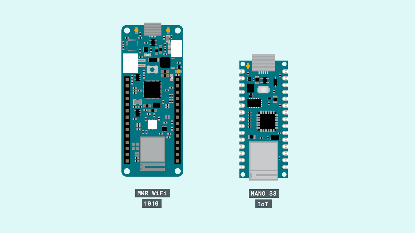
If you have connected an Arduino Nano 33 IoT or a MKR WiFi 1010 to the Arduino IoT Cloud, you can now update the sketch using a wireless connection from the web.
How it works
To use OTA, you need to do two things: enable a device and create a Thing.
To enable a device, you need to connect a board to the IoT Cloud and update the firmware. Just plug the device into the USB, go to the Device tab, and click Add Device. A wizard will guide you through the process — at the end, your board will be available as a target for the upload over-the-air and you will be able to update the sketch remotely!
A Thing is a component that manages the dialogue between the cloud and the physical device thanks to a dedicated library (the Arduino Connection Handler), and stores the data into the cloud. Creating a Thing is simple: just select the voice from the IoT Cloud’s main menu, configure the variables that you want to exchange with the device, and pair the board that you have just enabled.
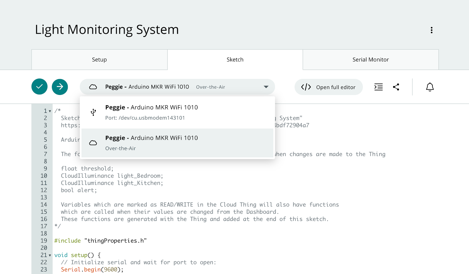
Devices that can be updated via OTA will appear in the dropdown list of all updatable devices in the online editors of Create — the full Web Editor and the new Sketch Editor have been introduced in the Thing configuration page to make minor changes to the code.
This Sketch Editor is one of the innovations that we have introduced in the IoT Cloud with two objectives in mind:
1. Help those who are learning to program with Arduino follow the tutorials of IoT projects, such as those included in the Oplà IoT Kit.
2. Allow users to quickly make small changes to the sketch, which do not require access to libraries or more sophisticated editing functions.
More resources
If you want to know more about OTA and the redesign of the IoT Cloud, we have prepared a couple of detailed tutorials that will walk you through the exploration of the new features.
New to Arduino Create? It’s a platform that helps you develop and manage connected projects with Arduino, featuring tools to code, monitor, and control devices from the Internet and your smartphones. Sign up for free now!
Don’t miss any updates and receive amazing projects from Arduino in your inbox!
On the 11th of August a team composed by researchers from FabLab Pisa and University of Pisa’s Center for Bioengineering and Robotics “E.Piaggio” will start a great adventure with a Summer School on the project called OS4BME (Open Source for Biomedical Engineering).
The aim of the project is to bring the DIY&Makers approach in the developing of simple, low cost/high impact biomedical devices, precisely, in this particular case, a neonatal Baby Monitor.
The course will take place at Kenyatta University (Nairobi) and it will involve setting up a 3D printing system, developing a neonatal monitoring device, using open source, electronics based on the Arduino platform and powered by solar panels.
Participants will play an active role in the identification of components, design, assembling and testing of the device and in the discussion of regulatory issues in its development. Close attention will also be paid to safety, ergonomic aspects and regulatory standards for biomedical devices.
The medical device industry in Africa is largely absent and there is an over reliance on foreign companies to repair and design biomedical instrumentation and resolve technical problems … More importantly, at present there are no specific engines or platforms focused on the sharing of biomedical instrumentation and devices. This is because, by their very nature, biomedical devices possess stringent performance requirements to comply with regulatory standards to ensure patient safety.
OS4BME is a project created by Prof. Arti Ahluwalia (Univ. Pisa), Daniele Mazzei and Carmelo De Maria (both from Fablab Pisa but also post-doc researchers at Centro E.Piaggio). The summer school is an initiative organized by a consortium of nine African universities with the objective of creating a sustainable health-care system, developing a network of academic excellence for Biomedical Engineering in Africa with the support of the ‘United Nations Economic Commission for Africa (UNECA).
Arduino is supporting the project and we sent to the team a bunch of Arduino UNO boards, Wi-Fi and GSM Shields to be used during the course and then will be donated to the Kenyatta University and Fablab Nairobi.
In the next week we’ll keep in touch with the team and receive updates directly from the summer school. Stay Tuned on this blog and on the work in progress of their WIKI!
The Following is an american TV Series which premiered last january and telling the story of
former FBI agent Ryan Hardy (Kevin Bacon) and his attempts to recapture serial killer Joe Carroll following the latter’s escape from prison
On the 9th of April Season 1, chapter 12 aired and some of you noticed the unexpected!
An Arduino Uno spotted for the first time in a TV series at 17m 40s: Kevin Bacon jumps over an ArduinoUno-activated device … the red led blinking seems pretty dangerous!
There’s a lot of acronyms in the title for this article – what I wanted to say was “Adventures with surface-mount technology soldering with the Wayne & Layne Blinky Persistence-of-vision surface-mount technology reprogrammable light emitting diode kit…” No, seriously. Anyhow – after my last attempt at working with hand soldering surface-mount components couldn’t really be called a success, I was looking for something to start again with. After a little searching around I found the subject for today’s review and ordered it post-haste. Delivery from the US to Australia was twelve calendar days – which is pretty good, so you know the organisation is shipping quickly once you paid.
The kit is by “Wayne and Layne” which was founded by two computer engineering graduates. They have a range of open-source electronics kits that look like fun and a lot of “blinkyness”. Our POV kit is a simple persistence-of-vision display. By using eight LEDs in a row you can display words and basic characters by waving the thing through the air at speed, giving the illusion of a larger display. An analogy to this would be a dot-matrix printer that prints with ink which only lasts a fraction of a second. More on that later, first – putting it together.
Assembly
Like most other kits it arrived in an anti-static bag, with a label clearly telling you where the instructions are:
Upon opening the amount of items included seemed a little light:
However the instructions are detailed:
… and upon opening, reveal the rest of the components:
… which are taped down to their matching description on the cardboard. When cutting the tape to access the parts, do it slowly otherwise you might send them flying off somewhere on the bench and spend ten minutes looking for it. Finally, the PCB in more detail:
After reviewing the instructions, it was time to fire up my trusty Hakko and get started. At this point a few tools will come in handy, including SMT tweezers, some solder wick and a piece of blu-tac:
Following the instructions, and taking your time are the key to success. When mounting the two-pad components – put a blob of solder on one pad, then use tweezers to move the component in whilst keeping that pad of solder molten, remove the iron, then let go with the tweezers. Then the results should resemble capacitor C1 on the board as shown below:
Then a quick blob at the other end seals it in. This was easily repeated for the resistors. The next step was the pre-programmed PIC microcontroller. It is in the form of a SOIC package type, and required some delicate work. The first step was to stick it down with some blu-tac:
… then solder down one pin at each end. Doing so holds it in place and you can remove the blu-tac and solder the rest of the pins in. I couldn’t solder each pin individually, so dragged solder across the pins then tried to soak up the excess with solder wick. I didn’t find this too successful, so instead used the solder sucker to mop up the excess:
If you solder, you should get one of these – they’re indispensable. Moving forward, the PIC finally sat well and looked OK:
Next was the power-switch. It clicks neatly into the PCB making soldering very easy. Then the LEDs. They’re tiny and some may find it difficult to identify the anode and cathode. If you look at the top, there is a tiny dot closer to one end – that end is the cathode. For example, in the lineup:
Soldering in the LEDs wasn’t too bad – however to save time do all the anodes first, then the cathodes:
At this point all the tricky work is over. There are the light-sensor LEDs and the reset button for the top:
And the coin-cell battery holder for the bottom. The battery is also included with the kit:
Operation
Once you’ve put the battery in, turn it on and wave it about in front of yourself. There are some pre-programmed messages and symbols already loaded, which you can change with the button. However you’ll want to put your own messages into the POV – and the process for doing so is very clever. Visit the programming page, and follow the instructions. Basically you enter the text into the form, set the POV to programming mode – and hold it up against two squares on your monitor. The website will then blink the data which is received by the light-sensitive LEDs. Once completed, the POV will inform you of success or failure. This method of programming is much simpler than having to flash the microcontroller every time – well done Wayne and Layne. A pin and connector is also included which allows you to wear the blinky as a badge. Maybe at a hackerspace, but not in public.
Once programmed some fun can be had trying out various speeds of waving the blinky. For example, here it is with the speed not fast enough at all:
… and a little bit faster:
And finally with me running past the camera:
Furthermore, there is an ‘easter egg’ in the software, which is shown below:
Conclusion
We had a lot of fun with this simple little kit, and learned a thing or two about hand-soldering SMT. It can be done with components that aren’t too small – however doing so was an interesting challenge and the results were quite fun. So it met our needs very well. Anyone can do it with some patience and a clean soldering iron. You can order the Blinky POV SMT kit directly from Wayne & Layne. Full-sized images available on flickr. This kit was purchased without notifying the supplier.
In the meanwhile have fun and keep checking into tronixstuff.com. Why not follow things on twitter, Google+, subscribe for email updates or RSS using the links on the right-hand column? And join our friendly Google Group – dedicated to the projects and related items on this website. Sign up – it’s free, helpful to each other – and we can all learn something.
Planet Arduino is, or at the moment is wishing to become, an aggregation of public weblogs from around the world written by people who develop, play, think on Arduino platform and his son. The opinions expressed in those weblogs and hence this aggregation are those of the original authors. Entries on this page are owned by their authors. We do not edit, endorse or vouch for the contents of individual posts. For more information about Arduino please visit www.arduino.cc
You are currently browsing the archives for the device category.


