14
Hey guys welcome back to the Techatronic. So today we are making a project which can be used at many places the project name is LED VU Meter using Arduino . In this project we are going to use Some LEDs. All we know how to work LED view metre and where it is used we have seen this view metre in tape recorder videos music system TVS and many other devices which is associated with the music so today we are going to make the same view metre which will be react with the music or sound.
LED VU Meter Introduction.
An LED VU meter is a device or we can say a circuit used to visually display the level of an audio signal. The term “VU” stands for Volume Unit, and it’s used in Audio engineering also it’s and standard measurement unit of audio. VU meter also represent the loudness of the audio signals.
In a LED VU meter, the audio signal is typically passed through a microphone sensor to measure its intensity or volume. This measurement is then translated into a visual representation using light-emitting diodes (LEDs). multiple LEDs are arranged in a row, with each LED corresponding to a specific level of the audio signal.
As the audio signal’s level changes in LED VU Meter using Arduino , the LEDs light up or dim accordingly, providing a visual indication of the signal’s intensity. LED VU meters are commonly found in audio equipment such as amplifiers, mixers, and audio interfaces, where they help users monitor and adjust audio levels for optimal performance. They are particularly useful in settings where precise control over audio levels is important, such as recording studios, live sound reinforcement, and broadcasting.
How to make music reactive LED view metre using anode arduino. So the first step to recognise what are the component required to make this project. Next step is to make a circuit diagram according to our requirement in which were using LED resistance and music sensor. Now you required a code which can be compile and upload to the Arduino.
Components Required:-
- Arduino Uno
- Sound sensor
- jumper wire
- Breadboard
- 220 Ohm resistor
Musical LED VU Meter using Arduino Uno Circuit Diagram

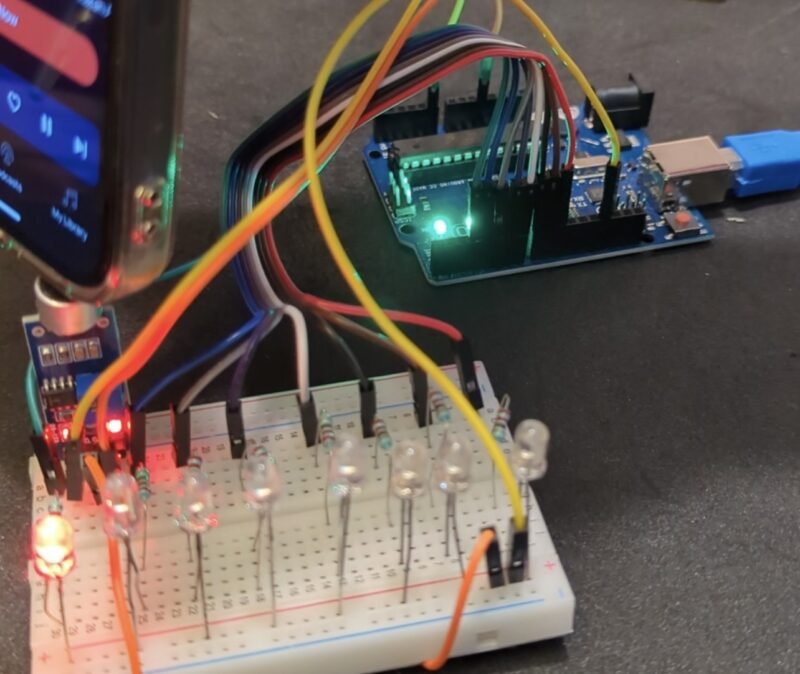
Here, we have completed the connection diagram of the project. it is pretty simple. put all the 8 LEDs on the breadboard as we have given.
- Connect all led ground wire to the Arduino ground wire through the breadboard
- Connect LED1, LED2, LED3, LED4, LED5 , LED6 , LED7, LED8 positive pin with Arduino pin 3,4,5,6,7,8,9,10 respectively with 1 220 ohm resistor in series as given in circuit.
- Connect Sound sensor ground wire with the Arduino Ground wire.
- Connect sound sensor vcc to the 5v pin of arduino uno
- Connect Sound Sensor A0 pin with Arduino A0 pin.
- Connect
After completing the connect we need to write the code for the Musical LED VU Meter using Arduino Uno Circuit Diagram project.
Musical LED VU Meter using Arduino Uno Code
void setup() {
  // put your setup code here, to run once:
pinMode(A0, INPUT);
pinMode(3, OUTPUT);
pinMode(4, OUTPUT);
pinMode(5, OUTPUT);
pinMode(6, OUTPUT);
pinMode(7, OUTPUT);
pinMode(8, OUTPUT);
pinMode(9, OUTPUT);
pinMode(10, OUTPUT);
Serial.begin(9600);
}

void loop() {
  // put your main code here, to run repeatedly:
int m = analogRead(A0);
//Serial.println(m);

//if(m>=530 && m<= 545)


int z = -(m-540);

int c = map(z, 0 , 200, 2, 10);
Serial.println(c);

if(c==3)
{
  digitalWrite(3, LOW);
digitalWrite(4, LOW);
digitalWrite(5, LOW);
digitalWrite(6, LOW);
digitalWrite(7, LOW);
digitalWrite(8, LOW);
digitalWrite(9, LOW);
digitalWrite(10, LOW);

delay(10);
  digitalWrite(3, HIGH);

delay(50);
}


else if(c==4)
{
  digitalWrite(3, LOW);
digitalWrite(4, LOW);
digitalWrite(5, LOW);
digitalWrite(6, LOW);
digitalWrite(7, LOW);
digitalWrite(8, LOW);
digitalWrite(9, LOW);
digitalWrite(10, LOW);

delay(10);
  digitalWrite(3, HIGH);
digitalWrite(4, HIGH);
delay(50);
}


else if(c==5)
{
  digitalWrite(3, LOW);
digitalWrite(4, LOW);
digitalWrite(5, LOW);
digitalWrite(6, LOW);
digitalWrite(7, LOW);
digitalWrite(8, LOW);
digitalWrite(9, LOW);
digitalWrite(10, LOW);

delay(10);
  digitalWrite(3, HIGH);
digitalWrite(4, HIGH);
digitalWrite(5, HIGH);
delay(50);

}

else if(c==6)
{
  digitalWrite(3, LOW);
digitalWrite(4, LOW);
digitalWrite(5, LOW);
digitalWrite(6, LOW);
digitalWrite(7, LOW);
digitalWrite(8, LOW);
digitalWrite(9, LOW);
digitalWrite(10, LOW);

delay(10);
  digitalWrite(3, HIGH);
digitalWrite(4, HIGH);
digitalWrite(5, HIGH);
digitalWrite(6, HIGH);
delay(50);
}

//Musical LED VU Meter using Arduino Uno
else if(c==7)
{
  digitalWrite(3, LOW);
digitalWrite(4, LOW);
digitalWrite(5, LOW);
digitalWrite(6, LOW);
digitalWrite(7, LOW);
digitalWrite(8, LOW);
digitalWrite(9, LOW);
digitalWrite(10, LOW);

delay(10);
  digitalWrite(3, HIGH);
digitalWrite(4, HIGH);
digitalWrite(5, HIGH);
digitalWrite(6, HIGH);
digitalWrite(7, HIGH);
delay(50);
}

else if(c==8)
{
  digitalWrite(3, LOW);
digitalWrite(4, LOW);
digitalWrite(5, LOW);
digitalWrite(6, LOW);
digitalWrite(7, LOW);
digitalWrite(8, LOW);
digitalWrite(9, LOW);
digitalWrite(10, LOW);

delay(10);
  digitalWrite(3, HIGH);
digitalWrite(4, HIGH);
digitalWrite(5, HIGH);
digitalWrite(6, HIGH);
digitalWrite(7, HIGH);
digitalWrite(8, HIGH);
delay(50);
}


else if(c==9)
{
  digitalWrite(3, LOW);
digitalWrite(4, LOW);
digitalWrite(5, LOW);
digitalWrite(6, LOW);
digitalWrite(7, LOW);
digitalWrite(8, LOW);
digitalWrite(9, LOW);
digitalWrite(10, LOW);

delay(10);
  digitalWrite(3, HIGH);
digitalWrite(4, HIGH);
digitalWrite(5, HIGH);
digitalWrite(6, HIGH);
digitalWrite(7, HIGH);
digitalWrite(8, HIGH);
digitalWrite(9, HIGH);
delay(50);
}

else if(c==10)
{
  digitalWrite(3, LOW);
digitalWrite(4, LOW);
digitalWrite(5, LOW);
digitalWrite(6, LOW);
digitalWrite(7, LOW);
digitalWrite(8, LOW);
digitalWrite(9, LOW);
digitalWrite(10, LOW);

delay(10);
  digitalWrite(3, HIGH);
digitalWrite(4, HIGH);
digitalWrite(5, HIGH);
digitalWrite(6, HIGH);
digitalWrite(7, HIGH);
digitalWrite(8, HIGH);
digitalWrite(9, HIGH);
digitalWrite(10, HIGH);
delay(50);
}

else
{

  digitalWrite(3, LOW);
digitalWrite(4, LOW);
digitalWrite(5, LOW);
digitalWrite(6, LOW);
digitalWrite(7, LOW);
digitalWrite(8, LOW);
digitalWrite(9, LOW);
digitalWrite(10, LOW);

delay(50);
  }


}
Here, we have given the code. now you need to upload the code into the arduino. if you have any difficulty to upload the code you can see the article how to upload code into the Arduino using Arduino IDE.
Still face any issue you can ask in the comment section.
Working of LED VU Meter.
How does the Led vu meter using Arduino works. There is a microphone sensor or sound sensor we are using in this circuit. which can sense the sound intensity. The sensor should be analog output sensor. so, we can get the intensity of sound too. this sensor sense the sound beat and giving the analog output according to the intensity of sound.
we are connecting the sensor output with the Arduino input analog pin. where we are getting all the sound data continuously in microseconds.there in code we assign the LEDs with the intensity of code which is given in below code. let me understand you.
int m = analogRead(A0); // here we are reading the A0 pin. where the sensor is connected

//Serial.println(m);

//if(m>=530 && m<= 545).  //


int z = -(m-540);

int c = map(z, 0 , 200, 2, 10);
Serial.println(c);   // here we have done some calculation to get the exacxt value of sound.

if(c==3)
{
  digitalWrite(3, LOW);
digitalWrite(4, LOW);
digitalWrite(5, LOW);
digitalWrite(6, LOW);
digitalWrite(7, LOW);
digitalWrite(8, LOW);
digitalWrite(9, LOW);
digitalWrite(10, LOW);

delay(10);
  digitalWrite(3, HIGH);  // this is the first intensity value in which we are glowing one led.

delay(50);
}
the code is very simple for LED VU Meter using Arduino Uno Circuit Diagram . i
The post LED VU Meter using Arduino Uno | Arduino Music Control LED Light appeared first on Techatronic.