Posts | Comments

Planet Arduino

Archive for the ‘eleven’ Category

Aug
14

Introduction

Controlling motors with an Arduino is a fun and generally integral part of the learning process for most up-and-coming embedded electronics enthusiasts. Or quite simply, using motors is fun ’cause you can make robots, tanks and stuff that moves. And thanks to Freetronics we have their new HBRIDGE motor shield for Arduino to review, so let’s check it out and get some things moving with it.

Arriving in retail-friendly packaging, the HBRIDGE can be stored with the included reusable packaging, and also has a quick-start guide that explains the technical specifications and URLs for tutorials:

HBRIDGE

The shield is compatible with the latest R3-series Arduino boards including the Leonardo and of course the Freetronics Eleven board:

HBRIDGE shield Freetronics Eleven

Specifications

The HBRIDGE shield is based on the Allegro A4954 Dual Full-Bridge DMOS PWM Motor Driver. For the curious, you can download the data sheet (pdf). This allows very simple control of two DC motors with a maximum rating of 40V at 2A, or one bipolar stepper motor. Unlike other motor shields I’ve seen, the HBRIDGE has a jumper which allows the power supply for the motor shield to be fed into the Arduino’s Vin line – so if your motor power supply is under 12V DC you can also power the Arduino from the same supply. Or you can run the motors from the Arduino’s power supply – if you’re sure that you won’t exceed the current rating. Frankly the former would be a safer and this the preferable solution.

The motor(s) are controlled very simply via PWM and digital logic. You feed the A4954 a PWM signal from a digital output pin for motor speed, and also set two inputs with a combination of high/low to set the motor direction, and also put the motor controlled into coast or brake mode. However don’t panic, it’s really easy.

Using the shield

How easy? Let’s start with two DC motors. One example of this is the tank chassis used in Chapter 12 of my book “Arduino Workshop - A Hands-On Introduction with 65 Projects“:

arduino_workshop_tank

The chassis is pretty much a standard tank chassis with two DC motors that run from an internal 9V battery pack. Search the Internet for “Dagu Rover 5″ for something similar. Connection is a simple manner of feeding the power lines from the battery and the motor wires into the terminal block on the HBRIDGE shield.

Next, take note of two things. First – the slide switches below the jumpers. Using these you can select the maximum amount of current allowed to flow from the power supply to each motor. These can be handy to ensure your motor doesn’t burn out by drawing too much current in a stall situation, so you can set these to the appropriate setting for your motor – or if you’re happy there won’t be any issues just leave them both on 2A.

The second thing to note is the six jumpers above the switches. These control which digital pins on your Arduino are used to control the motor driver. Each motor channel requires two outputs and one PWM output. If you leave them all on, the Arduino pins used will be the ones listed next to each jumper, otherwise remove the jumpers and manually wire to the required output. For the purposes of our demonstration, we’ll leave all the jumpers in. A final word of warning is to be careful not to touch the A4954 controller IC after some use – it can become really hot … around 160 degrees Celsius. It’s the circled part in the image below:

A4954_controller_IC

So back to the DC motors. You have two digital outputs to set, and also a PWM signal to generate – for each channel. If you set the outputs to 1 and 0  - the motor spins in one direction. Use 0 and 1 to spin the other way. And the value of the PWM (0~255) determines the speed. So consider the following sketch:

// Freetronics HBridge shield demonstration

int motora1 = 4;
int motora2 = 7;
int motoraspeed = 6;
int motorb1 = 3;
int motorb2 = 2;
int motorbspeed = 5;

void setup()
{
  pinMode(motora1, OUTPUT);
  pinMode(motora2, OUTPUT);
  pinMode(motoraspeed, OUTPUT); 
  pinMode(motorb1, OUTPUT);
  pinMode(motorb2, OUTPUT);
  pinMode(motorbspeed, OUTPUT);  
  delay(5000); 
}

void allOff()
// turns both motors off
{
  digitalWrite(motora1, LOW);
  digitalWrite(motora2, LOW);
  digitalWrite(motoraspeed, LOW);
  digitalWrite(motorb1, LOW);
  digitalWrite(motorb2, LOW);
  digitalWrite(motorbspeed, LOW);  
}

void goForward(int speed)
{
  digitalWrite(motora1, HIGH);
  digitalWrite(motora2, LOW);
  digitalWrite(motoraspeed, speed);
  digitalWrite(motorb1, HIGH);
  digitalWrite(motorb2, LOW);
  digitalWrite(motorbspeed, speed);  
}

void goBackward(int speed)
{
  digitalWrite(motora1, LOW);
  digitalWrite(motora2, HIGH);
  digitalWrite(motoraspeed, speed);
  digitalWrite(motorb1, LOW);
  digitalWrite(motorb2, HIGH);
  digitalWrite(motorbspeed, speed); 
}

void turnRight(int speed)
{
  digitalWrite(motora1, LOW);
  digitalWrite(motora2, HIGH);
  digitalWrite(motoraspeed, speed);
  digitalWrite(motorb1, HIGH);
  digitalWrite(motorb2, LOW);
  digitalWrite(motorbspeed, speed); 
}

void turnLeft(int speed)
{
  digitalWrite(motora1, HIGH);
  digitalWrite(motora2, LOW);
  digitalWrite(motoraspeed, speed);
  digitalWrite(motorb1, LOW);
  digitalWrite(motorb2, HIGH);
  digitalWrite(motorbspeed, speed); 
}

void loop()
{
  goForward(255);
  delay(1000);
  turnLeft(200);
  delay(1000);
  goBackward(255);
  delay(1000);
  turnRight(200);
  delay(1000);
}

Instead of chasing the tank chassis with a camera, here it is on the bench:

Now to try out a stepper motor. You can control a bipolar motor with the HBRIDGE shield, and each coil (pole) is connected to a motor channel.

Hint – if you’re looking for a cheap source of stepper motors, check out discarded office equipment such as printers or photocopiers. 

For the demonstration, I’ve found a random stepper motor from a second-hand store and wired up each pole to a channel on the HBRIDGE shield – then run the Arduino stepper motor demonstration sketch by Tom Igoe:

/*
 Based on example by Tom Igoe included in Arduino IDE
 at File -> Examples -> Stepper -> stepper_oneRevolution

 Modified to suit pinouts of Freetronics HBridge Shield
*/

#include <Stepper.h>

const int stepsPerRevolution = 240;  // change this to fit the number of steps per revolution
                                     // for your motor

// initialize the stepper library using the default pins on the HBridge Shield:
Stepper myStepper(stepsPerRevolution, 4, 7, 3, 2);

void setup() {
  // set the speed at 200 rpm:
  myStepper.setSpeed(200);
  // initialize the serial port:
  Serial.begin(38400);
}

void loop() {
  // step one revolution  in one direction:
   Serial.println("clockwise");
  myStepper.step(stepsPerRevolution);
  delay(1000);

   // step one revolution in the other direction:
  Serial.println("counterclockwise");
  myStepper.step(-stepsPerRevolution);
  delay(1000); 
}

With the following results:

Considering it was a random stepper motor for which we didn’t have the specifications for – it’s always nice to have it work the first time! For more formal situations, ensure your stepper motor matches the power supply voltage and so on. Nevertheless it shows how easy it can be to control something that appears complex to some people, so enjoy experimenting with them if you can.

Competition

Thanks to Freetronics we have a shield to give away to one lucky participant. To enter, clearly print your email address on the back of a postcard and mail it to:

H-Bridge Competition, PO Box 5435 Clayton 3168 Australia.

Entries must be received by the 20th of  September 2013. One postcard will then be drawn at random, and the winner will receive one H-Bridge shield delivered by Australia Post standard air mail. One entry per person – duplicates will be destroyed. We’re not responsible for customs or import duties, VAT, GST, import duty, postage delays, non-delivery or whatever walls your country puts up against receiving inbound mail.

Conclusion

As demonstrated, the HBRIDGE shield “just works” – which is what you need when bringing motorised project ideas to life. The ability to limit current flow and also power the host board from the external supply is a great idea, and with the extra prototyping space on the shield you can also add extra circuitry without needing another protoshield. Very well done. For more information and to order, visit the Freetronics website. Full-sized images are on flickr. And if you made it this far – check out my new book “Arduino Workshop” from No Starch Press.

tronixstuff

In the meanwhile have fun and keep checking into tronixstuff.com. Why not follow things on twitterGoogle+, subscribe  for email updates or RSS using the links on the right-hand column? And join our friendly Google Group – dedicated to the projects and related items on this website. Sign up – it’s free, helpful to each other –  and we can all learn something.

Note – The motor shield used in this article was a promotional consideration supplied by Freetronics.

The post Part review – Freetronics HBRIDGE motor driver shield for Arduino appeared first on tronixstuff.

Jun
20

Introduction

Recently the Arduino Leonardo was released, and I’ve finally got my hands on one. Some have claimed that the Leonardo as the successor to the Arduino Uno board, however that is somewhat subjective.  In this article we have a look for ourselves and examine the differences between the Uno boards that we’re used to and the new Leonardo.

The board

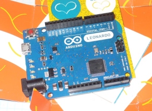
Here it is unwrapped from the cardboard packet:

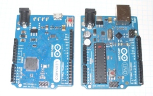
It uses the same physical footprint as the Uno, so no surprises there:

 Now to travel around the board and see what’s new. First is the microcontroller – we have the Atmel ATmega32U4:

There are several pros and cons to using the 32U4. The pros include:

  • More analogue inputs. As well as the usual A0~A5, digital pins 4,6,8,9,10 and 12 can be configured as A6~A11
  • It handles USB. So no more external USB controller MCU or the old FTDI chip. Supposedly this saves money, however the retail price in some markets don’t reflect this
  • More PWM pins – well one more. They’re now on D3, 5, 6, 9, 10, 11 and 13
  • There is a little more SRAM than the Uno, it is now 2.5 kB
  • SPI has moved – they’re now wired to the ICSP pins. So you now have D10~D13 seperate to SPI
And the cons:
  • SPI has moved – they’re now wired to the ICSP pins. So if you have any shields that use SPI – too bad, they’re out. The most common example of this will be Ethernet shields – you’ll need to modify them with some jumper leads to contact the ICSP pins
  • I2C has moved over to D2+3. So if you have any shields using I2C – they’ll need to be modified
  • Less flash memory – the bootloader uses 4 kB of the 32 kB flash (the Uno used 0.5 kB)

However you can get an adaptor shield to use older Arduino shields with the Leonardo.

For MCU to Arduino pin mapping, see here. Next, for more on the USB side of things – as the 32U4 takes care of USB – take heed of the following notes from arduino.cc:

Since the Leonardo does not have a dedicated chip to handle serial communication, it means that the serial port is virtual– it’s a software routine, both on your operating system, and on the Leonardo itself. Just as your computer creates an instance of the serial port driver when you plug in any Arduino, the Leonardo creates a serial instance whenever it runs its bootloader. The Leonardo is an instance of USB’s Connected Device Class (CDC) driver.

This means that every time you reset the board, the Leonardo’s USB serial connection will be broken and re-established. The Leonardo will disappear from the list of serial ports, and the list will re-enumerate. Any program that has an open serial connection to the Leonardo will lose its connection. This is in contrast to the Arduino Uno, with which you can reset the main processor (the ATmega328P) without closing the USB connection (which is maintained by the secondaryATmega8U2 or ATmega16U2 processor).

There are some other changes to the board. Moving on, the next change is the USB socket. Do you recognise this socket?

Yes – micro USB. Thankfully (!) a growing number of mobile phones use this type for charging and USB connection, so you may already have a matching cable. Note that the Leonardo doesn’t include a cable, so if you’re an iPhone user – order yourself a cable with your Leonardo.

Next, the LEDs have been moved to the edge of the board. You can see them in the above image to the right of the USB socket. No more squinting through shields at strange angles to check the TX/RX lights. However this isn’t a new invention, our friends at Freetronics have been doing this for some time. Furthermore, the reset button has been moved to the corner for easier access.

There are also seperate connectors for the I2C bus – next to AREF, which should make modifying existing shields a little easier:

 Finally, due to the reduction in components and shift to SMD – there is what could almost be called a large waste of space on the board:

A few extra user LEDs wouldn’t have been a bad idea, or perhaps circuitry to support Li-Po rechargeable batteries. However the argument will be “that’s what a protoshield is for”. Just saying… As for the rest of the hardware, the specifications can be found here.

Finally, the Leonardo is available in two versions – with and without headers. This makes it easier to embed the Leonardo into fixed applications as you can directly solder to the various I/O pins. An alternative to this would instead be the Freetronics LeoStick, as it is much smaller yet fully compatible.

Software

First – you need to drag yourself into Arduino IDE v1.0.1. Note you can run more than one version of the IDE on the same machine if you don’t mind sharing the same preferences file. Next, the Leonardo doesn’t reset when you open the serial monitor window (from arduino.cc) -

That means you won’t see serial data that’s already been sent to the computer by the board, including, for example, most data sent in the setup() function. This change means that if you’re using any Serial print(), println() or write() statments in your setup, they won’t show up when you open the serial monitor. To work around this, you can check to see if the serial port is open like so:

 // while the serial stream is not open, do nothing:
   while (!Serial) ;

Using the 32U4, you also have two serial ports. The first is the emulated one via the USB, and the second is the hardware UART on digital pins 0 and 1. Furthermore, the Leonardo can emulate a USB keyboard and mouse – however with a few caveats. There is a section on the Leonardo homepage that you should really read and take note of. But this emulation does sound interesting, and we look forward to developing some interesting tools to take use of them, so stay tuned.

Conclusion

There is nothing wrong with the Leonardo board, it works as described. However you could consider this a virtual “line in the sand”, or a new beginning. Due to the changes in the pinouts shields will need to be redesigned, and for those of you still programming in Arduino v23 – it’s time to get up to speed with v1.0.1. If you need the special USB functions, keyboard and/or mouse emulation, or are happy with the changes and can get one for less than the cost of a Uno – great.

Here’s a video from the main man Massimo Banzi:

However if you’re looking for your first Arduino board – this isn’t the board for you right now. There are too many incompatible shields out there, and the inability to cheaply replace the microcontroller will see some beginners burn out their first couple of boards rendering them useless. Get yourself an Arduino Uno or compatible board such as the Freetronics Eleven.

In conclusion, classifying the Leonardo board as good or bad is not a simple decision. It may or may not be an improvement – depending on your needs. Right now – for beginners, this is not the board for you. For those who understand the differences between a Uno and Leonardo, sure – no problem. Frankly, I would get a LeoStick instead.  At the end – it’s up to you to make an informed decision.

If you have any comments, leave them below. Thanks to Little Bird Electronics for the use of the Arduino Leonardo board.

In the meanwhile have fun and keep checking into tronixstuff.com. Why not follow things on twitterGoogle+, subscribe  for email updates or RSS using the links on the right-hand column? And join our friendly Google Group – dedicated to the projects and related items on this website. Sign up – it’s free, helpful to each other –  and we can all learn something.

Introduction

Recently the Arduino Leonardo was released, and I’ve finally got my hands on one. Some have claimed that the Leonardo as the successor to the Arduino Uno board, however that is somewhat subjective.  In this article we have a look for ourselves and examine the differences between the Uno boards that we’re used to and the new Leonardo.

The board

Here it is unwrapped from the cardboard packet:

It uses the same physical footprint as the Uno, so no surprises there:

 Now to travel around the board and see what’s new. First is the microcontroller – we have the Atmel ATmega32U4:

There are several pros and cons to using the 32U4. The pros include:

  • More analogue inputs. As well as the usual A0~A5, digital pins 4,6,8,9,10 and 12 can be configured as A6~A11
  • It handles USB. So no more external USB controller MCU or the old FTDI chip. Supposedly this saves money, however the retail price in some markets don’t reflect this
  • More PWM pins – well one more. They’re now on D3, 5, 6, 9, 10, 11 and 13
  • There is a little more SRAM than the Uno, it is now 2.5 kB
  • SPI has moved – they’re now wired to the ICSP pins. So you now have D10~D13 seperate to SPI
And the cons:
  • SPI has moved – they’re now wired to the ICSP pins. So if you have any shields that use SPI – too bad, they’re out. The most common example of this will be Ethernet shields – you’ll need to modify them with some jumper leads to contact the ICSP pins
  • I2C has moved over to D2+3. So if you have any shields using I2C – they’ll need to be modified
  • Less flash memory – the bootloader uses 4 kB of the 32 kB flash (the Uno used 0.5 kB)

However you can get an adaptor shield to use older Arduino shields with the Leonardo.

For MCU to Arduino pin mapping, see here. Next, for more on the USB side of things – as the 32U4 takes care of USB – take heed of the following notes from arduino.cc:

Since the Leonardo does not have a dedicated chip to handle serial communication, it means that the serial port is virtual– it’s a software routine, both on your operating system, and on the Leonardo itself. Just as your computer creates an instance of the serial port driver when you plug in any Arduino, the Leonardo creates a serial instance whenever it runs its bootloader. The Leonardo is an instance of USB’s Connected Device Class (CDC) driver.

This means that every time you reset the board, the Leonardo’s USB serial connection will be broken and re-established. The Leonardo will disappear from the list of serial ports, and the list will re-enumerate. Any program that has an open serial connection to the Leonardo will lose its connection. This is in contrast to the Arduino Uno, with which you can reset the main processor (the ATmega328P) without closing the USB connection (which is maintained by the secondaryATmega8U2 or ATmega16U2 processor).

There are some other changes to the board. Moving on, the next change is the USB socket. Do you recognise this socket?

Yes – micro USB. Thankfully (!) a growing number of mobile phones use this type for charging and USB connection, so you may already have a matching cable. Note that the Leonardo doesn’t include a cable, so if you’re an iPhone user – order yourself a cable with your Leonardo.

Next, the LEDs have been moved to the edge of the board. You can see them in the above image to the right of the USB socket. No more squinting through shields at strange angles to check the TX/RX lights. However this isn’t a new invention, our friends at Freetronics have been doing this for some time. Furthermore, the reset button has been moved to the corner for easier access.

There are also seperate connectors for the I2C bus – next to AREF, which should make modifying existing shields a little easier:

 Finally, due to the reduction in components and shift to SMD – there is what could almost be called a large waste of space on the board:

A few extra user LEDs wouldn’t have been a bad idea, or perhaps circuitry to support Li-Po rechargeable batteries. However the argument will be “that’s what a protoshield is for”. Just saying… As for the rest of the hardware, the specifications can be found here.

Finally, the Leonardo is available in two versions – with and without headers. This makes it easier to embed the Leonardo into fixed applications as you can directly solder to the various I/O pins. An alternative to this would instead be the Freetronics LeoStick, as it is much smaller yet fully compatible.

Software

First – you need to drag yourself into Arduino IDE v1.0.1. Note you can run more than one version of the IDE on the same machine if you don’t mind sharing the same preferences file. Next, the Leonardo doesn’t reset when you open the serial monitor window (from arduino.cc) -

That means you won’t see serial data that’s already been sent to the computer by the board, including, for example, most data sent in the setup() function. This change means that if you’re using any Serial print(), println() or write() statments in your setup, they won’t show up when you open the serial monitor. To work around this, you can check to see if the serial port is open like so:

// while the serial stream is not open, do nothing:
while (!Serial) ;

Using the 32U4, you also have two serial ports. The first is the emulated one via the USB, and the second is the hardware UART on digital pins 0 and 1. Furthermore, the Leonardo can emulate a USB keyboard and mouse – however with a few caveats. There is a section on the Leonardo homepage that you should really read and take note of. But this emulation does sound interesting, and we look forward to developing some interesting tools to take use of them, so stay tuned.

Conclusion

There is nothing wrong with the Leonardo board, it works as described. However you could consider this a virtual “line in the sand”, or a new beginning. Due to the changes in the pinouts shields will need to be redesigned, and for those of you still programming in Arduino v23 – it’s time to get up to speed with v1.0.1. If you need the special USB functions, keyboard and/or mouse emulation, or are happy with the changes and can get one for less than the cost of a Uno – great.

Here’s a video from the main man Massimo Banzi:

However if you’re looking for your first Arduino board – this isn’t the board for you right now. There are too many incompatible shields out there, and the inability to cheaply replace the microcontroller will see some beginners burn out their first couple of boards rendering them useless. Get yourself an Arduino Uno or compatible board such as the Freetronics Eleven.

In conclusion, classifying the Leonardo board as good or bad is not a simple decision. It may or may not be an improvement – depending on your needs. Right now – for beginners, this is not the board for you. For those who understand the differences between a Uno and Leonardo, sure – no problem. Frankly, I would get a LeoStick instead.  At the end – it’s up to you to make an informed decision.

In the meanwhile have fun and keep checking into tronixstuff.com. Why not follow things on twitterGoogle+, subscribe  for email updates or RSS using the links on the right-hand column? And join our friendly Google Group – dedicated to the projects and related items on this website. Sign up – it’s free, helpful to each other –  and we can all learn something.

The post First Look – the Arduino Leonardo appeared first on tronixstuff.
In this article we examine another style of vintage display technology – the incandescent seven-segment digital display. We are using the FFD51 by the IEE company (data sheet.pdf) – dating back to the early 1970s. Here is a close-up of our example:

You can see the filaments for each of the segments, as well as the small coiled ‘decimal point’ filament at the top-right of the image above.  This model has pins in a typical DIP format, making use in a solderless breadboard or integration into a PCB very simple:

It operates in a similar manner to a normal light bulb – the filaments are in a vacuum, and when a current is applied the filament glows nicely. The benefit of using such as display is their brightness – they could be read in direct sunlight, as well as looking good inside.  At five volts each segment draws around 30mA. For demonstration purposes I have been running them at a lower voltage (3.5~4V), as they are old and I don’t want to accidentally burn out any of the elements.

Using these with an Arduino is very easy as they segments can be driven from a 74HC595 shift register using logic from Arduino digital out pins. (If you are unfamiliar with doing so, please read chapters four and five of my tutorial series). For my first round of experimenting, a solderless breadboard was used, along with the usual Freetronics board and some shift register modules:

Although the modules are larger than a DIP 74HC595, I like to use these instead. Once you solder in the header pins they are easier to insert and remove from breadboards, have the pinouts labelled clearly, are almost impossible to physically damage, have a 100nF capacitor for smoothing and a nice blue LED indicating power is applied.

Moving forward – using four shift register modules and displays, a simple four-digit circuit can be created. Note from the datasheet that all the common pins need to be connected together to GND. Otherwise you can just connect the outputs from the shift register (Q0~Q7) directly to the display’s a~dp pins.

Some of you may be thinking “Oh at 30mA a pin, you’re exceeding the limits of the 74HC595!”… well yes, we are. However after several hours they still worked fine and without any heat build-up. However if you displayed all eight segments continuously there may be some issues. So take care. As mentioned earlier we ran the displays at a lower voltage (3.5~4V) and they still displayed nicely. Furthermore at the lower voltage the entire circuit including the Arduino-compatible board used less than 730mA with all segments on –  for example:

 For the non-believers, here is the circuit in action:

Here is the Arduino sketch for the demonstration above:

Now for the prototype of something more useful – another clock. :) Time to once again pull out my Arduino-compatible board with onboard DS1307 real-time clock. For more information on the RTC IC and getting time data with an Arduino please visit chapter twenty of my tutorials. For this example we will use the first two digits for the hours, and the last two digits for minutes. The display will then rotate to showing the numerical day and month of the year – then repeat.

Operation is simple – just get the time from the DS1307, then place the four digits in an array. The elements of the array are then sent in reverse order to the shift registers. The procedure is repeated for the date. Anyhow, here is the sketch:

#include "Wire.h"
#define DS1307_I2C_ADDRESS 0x68
// note the digital pins of the arduino that are connected to the nixie driver
int clockPin = 7;
int latchPin = 8;
int dataPin = 9;
int clockArray[5]; // holds the digits to display
int a=0;
// the bits represent segments a~dp from left to right
// if you add one to the number (or turn on the last bit) the decimal point turns on
byte numbers[]={
 B11111100, // digit zero
 B01100000,
 B11011010,
 B11110010,
 B01100110,
 B10110110,
 B10111110,
 B11100000,
 B11111110,
 B11110110}; // digit nine
// Convert normal decimal numbers to binary coded decimal
byte decToBcd(byte val)
{
 return ( (val/10*16) + (val%10) );
}
// Convert binary coded decimal to normal decimal numbers
byte bcdToDec(byte val)
{
 return ( (val/16*10) + (val%16) );
}
void setDateDs1307(byte second, // 0-59
byte minute, // 0-59
byte hour, // 1-23
byte dayOfWeek, // 1-7
byte dayOfMonth, // 1-28/29/30/31
byte month, // 1-12
byte year) // 0-99
{
 Wire.beginTransmission(DS1307_I2C_ADDRESS);
 Wire.send(0);
 Wire.send(decToBcd(second)); // 0 to bit 7 starts the clock
 Wire.send(decToBcd(minute));
 Wire.send(decToBcd(hour)); 
 Wire.send(decToBcd(dayOfWeek));
 Wire.send(decToBcd(dayOfMonth));
 Wire.send(decToBcd(month));
 Wire.send(decToBcd(year));
 Wire.send(0x10); // sends 0x10 (hex) 00010000 (binary) to control register - turns on square wave
 Wire.endTransmission();
}
// Gets the date and time from the ds1307
void getDateDs1307(byte *second,
byte *minute,
byte *hour,
byte *dayOfWeek,
byte *dayOfMonth,
byte *month,
byte *year)
{
 // Reset the register pointer
 Wire.beginTransmission(DS1307_I2C_ADDRESS);
 Wire.send(0);
 Wire.endTransmission();
 Wire.requestFrom(DS1307_I2C_ADDRESS, 7);
 // A few of these need masks because certain bits are control bits
 *second = bcdToDec(Wire.receive() & 0x7f);
 *minute = bcdToDec(Wire.receive());
 *hour = bcdToDec(Wire.receive() & 0x3f); // Need to change this if 12 hour am/pm
 *dayOfWeek = bcdToDec(Wire.receive());
 *dayOfMonth = bcdToDec(Wire.receive());
 *month = bcdToDec(Wire.receive());
 *year = bcdToDec(Wire.receive());
}
void setup()
{
 byte second, minute, hour, dayOfWeek, dayOfMonth, month, year;
 pinMode(latchPin, OUTPUT);
 pinMode(clockPin, OUTPUT);
 pinMode(dataPin, OUTPUT);
 Wire.begin();
// Change these values to what you want to set your clock to.
 // You probably only want to set your clock once and then remove
 // the setDateDs1307 call.
second = 00;
 minute = 35;
 hour = 17;
 dayOfWeek = 5;
 dayOfMonth = 29;
 month = 4;
 year = 12;
 // setDateDs1307(second, minute, hour, dayOfWeek, dayOfMonth, month, year);
}
void showTime()
{
 byte second, minute, hour, dayOfWeek, dayOfMonth, month, year;
 getDateDs1307(&second, &minute, &hour, &dayOfWeek, &dayOfMonth, &month, &year);

 if (hour<10)
 {
 clockArray[1]=0;
 clockArray[2]=hour;
 }
 if (hour>9)
 {
 clockArray[1]=int(hour/10);
 clockArray[2]=hour%10;
 } 
 if (minute<10)
 {
 clockArray[3]=0;
 clockArray[4]=minute;
 }
 if (minute>9)
 {
 clockArray[3]=int(minute/10);
 clockArray[4]=minute%10;
 }
 displayArray();
}
void showDate()
{
 byte second, minute, hour, dayOfWeek, dayOfMonth, month, year;
 getDateDs1307(&second, &minute, &hour, &dayOfWeek, &dayOfMonth, &month, &year);

 if (dayOfMonth<10)
 {
 clockArray[1]=0;
 clockArray[2]=dayOfMonth;
 }
 if (dayOfMonth>10)
 {
 clockArray[1]=int(dayOfMonth/10);
 clockArray[2]=dayOfMonth%10;
 }
 if (month<10)
 {
 clockArray[3]=0;
 clockArray[4]=month;
 }
 if (month>10)
 {
 clockArray[3]=int(month/10);
 clockArray[4]=month%10;
 }
 displayArray();
}
void displayArray()
// sends the data from clockArray[] to the shift registers
{
 digitalWrite(latchPin, LOW);
 shiftOut(dataPin, clockPin, LSBFIRST, numbers[clockArray[4]]); // digit 4 
 shiftOut(dataPin, clockPin, LSBFIRST, numbers[clockArray[3]]); // digit 3 
 shiftOut(dataPin, clockPin, LSBFIRST, numbers[clockArray[2]]+1); // digit 2 and decimal point
 shiftOut(dataPin, clockPin, LSBFIRST, numbers[clockArray[1]]); // digit 1
 digitalWrite(latchPin, HIGH);
}
void loop()
{
 showTime(); // display the time 
 delay(5000);
 showDate(); // display the date (day and month) for two seconds
 delay(2000);
}

and the clock in action:

So there you have it – another older style of technology dragged into the 21st century. If you enjoyed this article you may also like to read about vintage HP LED displays. Once again, I hope you found this article of interest. Thanks to the Vintage Technology Association website for background information.

Have fun and keep checking into tronixstuff.com. Why not follow things on twitterGoogle+, subscribe  for email updates or RSS using the links on the right-hand column, or join our Google Group – dedicated to the projects and related items on this website. Sign up – it’s free, helpful to each other –  and we can all learn something.

The post Arduino and FFD51 Incandescent Displays appeared first on tronixstuff.


  • Newsletter

    Sign up for the PlanetArduino Newsletter, which delivers the most popular articles via e-mail to your inbox every week. Just fill in the information below and submit.

  • Like Us on Facebook