We suppose it’s a bit early to call it just yet, but we definitely have a solid contender for Father of the Year. [DIY_Maxwell] made a light-up hockey game for his young son that looks like fun for all ages. Whenever the puck is hit with the accompanying DIY hockey stick (or anything else), it lights up and produces different sounds based on its acceleration.
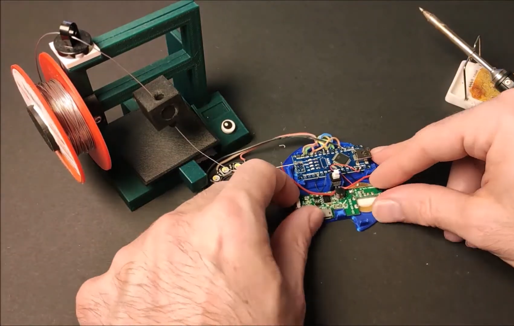
Inside the printed puck is an Arduino Nano running an MPU6050 accelerometer, a 12-NeoPixel ring, and a piezo buzzer. [DIY_Maxell] reused a power bank charging circuit to charge up the small LiPo battery.
The original circuit used a pair of coin cells, but the Arduino was randomly freezing up, probably because of the LEDs’ current draw. Be sure to check out the video after the break, which begins with a little stop motion and features a solder stand in the shape of a 3D printer.
If you’re planning to get into circuit sculpture one of these days, it would probably be best to start with something small and simple, instead of trying to make a crazy light-up spaceship or something with a lot of curves on the first go. A small form factor doesn’t necessarily mean it can’t also be useful. Why not start by making a small automatic night light?
The circuit itself is quite simple, especially because it uses an Arduino. You could accomplish the same thing with a 555, but that’s going to complicate the circuit sculpture part of things a bit. As long as the ambient light level coming in from the light-dependent resistor is low enough, then the two LEDs will be lit.
We love the frosted acrylic panels that [akshar1101] connected together with what looks like right angle header pins. If you wanted to expose the electronics, localize the light diffusion with a little acrylic cover that slips over the LEDs. Check it out in the demo after the break.
If you’ve got a party coming up and are looking to add a little bit of excitement, you might be interested in this recent project from [Gav Lewis]. The build is based on a commercially available party light, but with some upgraded components the final product is brighter and more dynamic than it was stock.
Realistically, [Gav] has changed out almost every component of this light except for the enclosure and the front lens. The original 5 mm LED array was replaced with a new 8×8 WS2812B panel, and the electronics completely replaced with an Arduino Nano. He’s still using the light’s original power supply, but as it only puts out around 4.2 V, he’s added a boost converter to provide a stable 5 V for the new hardware. He also added a small 12 V cooling fan, which he says is basically silent since it’s only getting half its rated voltage.
[Gav] has developed a number of lighting patterns with FastLED that do a good job of emulating what you might see from a much more expensive laser scanner. In the video after the break, you can see how multiple colored beams of light exit the housing at once, projecting patterns on the opposite wall. He says he’s like to restore the device’s original sound activation mode, but as of yet hasn’t gotten the code sorted out.
Anyone who has done anything with RGB LEDs knows that their ability to display pretty much any color is somehow both the best and worst thing about them. How do you get it right? How do you make your results repeatable? [Thomas] has the answer. He dug around in the ol’ parts cupboard, found a few pots, and got to work making this stay-home stew of a project — an on-demand RGB LED color mixer.
Three cleverly color-coded potentiometers and an Arduino let [Thomas] step through 0-255 to mix various values of red, blue, and green. The shade that gets made is displayed live on a set of 10 individual NeoPixels that are laid out under a frosty diffusing panel. Each of the RGB values are also shown on an 16×2 LCD.
This is one of those projects that hits a sweet spot of being simple, useful, and fun. It’s even nice-looking and compact. What more could you want from a project cobbled together from ingredients on hand? [Thomas] is even giving away the code recipe.
You are stuck at home quarantined and you want to do some Arduino projects. The problem is you don’t have all the cool devices you want to use. Sure, you can order them, but the stores are slow shipping things that aren’t essential these days. If you want to get a headstart while you are waiting for the postman, check out Wokwi’s Playground. For example, you can write code to drive a virtual NeoPixel 16×16 matrix. There’s even example code to get you started.
There are quite a few other choices in the playground including Charlieplexed LEDs, a keypad, and an LCD. There are also challenges. For example, in the traffic light challenge, you are given code that uses a task scheduler library to implement a traffic light. You have to add a turn signal to the code.
In addition to LEDs in various configurations, the site has some serial bus components, an LCD, a keypad, and a NeoPixel strip. There are also a few tools including an EasyEDA to KiCad converter and a way to share sourcecode similar to Pastebin.
Of course, simulations only get you so far, but the site is a fun way to play with some different I/O devices. It would be very nice if you could compose for the different components together, but you could work your code in sections, if necessary. You can do similar things with TinkerCad circuits. If you want to install software, there’s a simulator for you, too.
In a great display of one hacker’s work being the base for another’s, [Andy] started out with [Jussi Kilpelainen]’s core memory shield for Arduino. As he was playing with the shield he had a desire to “see” the core memory flipping and got the idea to add an LED matrix aligned behind the individual cores.
The first iteration worked, but it only showed the state that the Arduino believed the core memory to be in. What he really wanted was a live read on the actual state. He realized that an Adafruit Featherwing 8×8 matrix display also fits behind the core memory. Now the LEDs update based on the read state of the core memory. This allows him to flip the individual bits with a magnetic stylus and see the result. Very cool.
You can see a video of it working after the break.
For Game of Thrones fans, it’s an awkward time. The show has ended its run on HBO (not without a certain level of controversy), the planned prequel is still years away, and who knows when George R. R. Martin will actually get around to writing the final books in the series. Fans have no choice but to entertain themselves while waiting for further tales of adventure from Westeros, which is how we get things like this motorized clock from [Techarge].
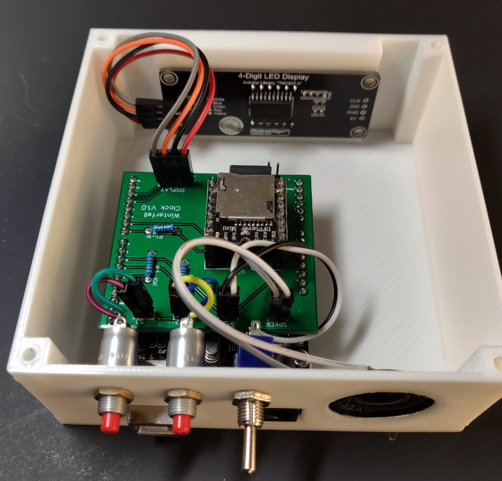
Inspired by the now iconic opening sequence from the HBO series, elements of the 3D printed model spin around while the theme song is played courtesy of a DFPlayer Mini MP3 player module and small 2 watt speaker. The audio hardware, motor, and four digit LED display module in the front are all connected to an Arduino with a custom PCB shield, giving the inside of the clock a very clean and professional appearance.
Around the back side [Techarge] has two small push buttons to set the hour and minutes, and a large toggle to control the music and movement. As of right now it needs to be switched on and off manually, but a future enhancement could see it kick on hourly. We’d also like to see an RTC module added to the PCB, or better yet, switch over to the ESP8266 and just pull the time down from NTP.
Who knows? By the time you’ve built one of these clocks for yourself, and the hand-made Iron Throne phone charger stand to go with it, maybe ol’ George will have slipped out a new book. But don’t count on it.
If we’ve learned anything over the years, it’s that hackers like weird clocks, and they love packing as many multicolored LEDs into a device as is humanly possible. Combine both of those concepts into one project, and you’ve got a perfect storm. So as far as unnecessarily complex timepieces go, we’d say the “Crazy Clock 4” built by [Fearless Night] ranks up there among the all-time greats.
This Arduino Pro Mini powered clock syncs the current time via GPS, with a temperature compensated DS3231 RTC to keep it on the straight and narrow between satellite downlinks. Once the clock has the correct time, how do you read it? Well, at the top you’ve got a basic numerical readout for the normies, and next to that there’s a circular LED display that looks like it could double as a sci-fi movie prop. On the lower level there’s a binary clock for the real show-offs, and as if that wasn’t enough, there’s even dual color-coded analog meters to show the hours and minutes.
[Fearless Night] has provided everything you need to follow along at home, from the Arduino source code to the 3D models of the case and Gerber files for the custom PCB. Personally we think just the top half of the clock would be more than sufficient for our timekeeping needs. If nothing else it should help save some energy, as the clock currently pulls an incredible 20 watts with all those LEDs firing off.
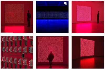
This seven segment art display makes use of a 81 seven segment red common cathode LED displays. The LEDs are arranged onto 100x100mm boards that each contain an Arduino Nano and 9 seven segment displays, daisy chained through three-pin headers located on the sides of the boards. The pins (power, ground, and serial) provide the signals necessary for propagating a program across each of the connected boards.
The first board – with two Arduino Nanos – sends instructions for which digits to light and drives the display, sending the instructions over to the next board on the chain.
In a multiplexed arrangement, a single Arduino Nano is able to drive up to 12 seven segment displays, but only 9 needed to be driven for the program, keeping D13’s built in LED and the serial pins free. Since no resistors are featured on the boards, current limiting is done through software. This was inspired by the Bubble LED displays on the Sinclair Scientific Calculator, and was done in order to achieve a greater brightness by controlling the current through the duty cycle.
The time between digits lighting up is 2ms, giving them some time to cool down. The animations in the demos featured falling and incrementing digits, as well as a random number generator using a linear feedback shift register.
This is a quick start guide for the Four Digit Seven Segment Display Module and Enclosure from PMD Way. This module offers a neat and bright display which is ideal for numeric or hexadecimal data. It can display the digits 0 to 9 including the decimal point, and the letters A to F. You can also control each segment individually if desired.
Each module contains four 74HC595 shift registers – once of each controls a digit. If you carefully remove the back panel from the enclosure, you can see the pin connections:
If you’re only using one display, use the group of pins at the centre-bottom of the board. From left to right the connections are:
Data out (ignore for single display use)
VCC – connect to a 3.3V or 5V supply
GND – connect to your GND line
SDI – data in – connect to the data out pin on your Arduino/other board
LCK – latch – connect to the output pin on your Arduino or other board that will control the latch
CLK – clock – connect to the output pin on your Arduino or other board that will control the clock signal
For the purposes of our Arduino tutorial, connect VCC to the 5V pin, GND to GND, SDI to D11, LCK to D13 and CLK to D12.
If you are connecting more than one module, use the pins on the left- and right-hand side of the module. Start with the connections from your Arduino (etc) to the right-hand side, as this is where the DIN (data in) pin is located.
Then connect the pins on the left-hand side of the module to the right-hand side of the new module – and so forth. SDO (data out) will connect to the SDI (data in) – with the other pins being identical for connection.
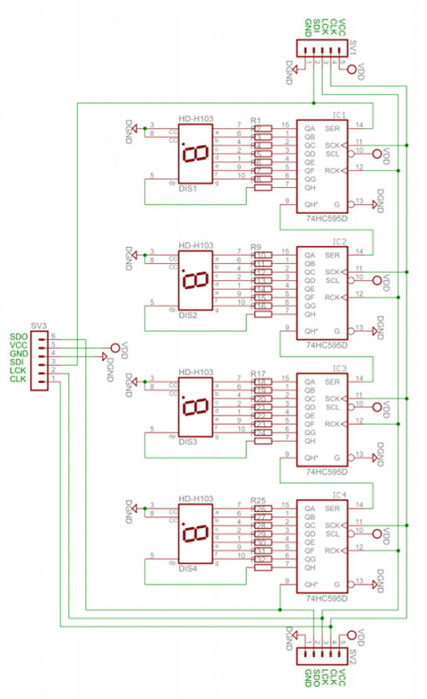
The module schematic is shown below:
Arduino Example Sketch
Once you have made the connections to your Arduino as outlined above, upload the following sketch:
// Demonstration Arduino sketch for four digit, seven segment display with enclosure
// https://pmdway.com/collections/7-segment-numeric-leds/products/four-digit-seven-segment-display-module-and-enclosure
int latchPin = 13;   // connect to LCK pin
intclockPin = 12;   // connect to CLK pin
intdataPin = 11;    // connect to SDI pin

int LED_SEG_TAB[]={
  0xfc,0x60,0xda,0xf2,0x66,0xb6,0xbe,0xe0,0xfe,0xf6,0x01,0xee,0x3e,0x1a,0x7a,0x9e,0x8e,0x01,0x00};
//0     1    2     3    4    5    6    7    8    9   dp   .    a    b    c    d    e    f   off

void setup()
{
  //set pins to output so you can control the shift register
  pinMode(latchPin, OUTPUT);
  pinMode(clockPin, OUTPUT);
  pinMode(dataPin, OUTPUT);
}

void displayNumber(int value, boolean leadingZero)
// break down "value" into digits and store in a,b,c,d
{
  int a,b,c,d;
  a = value / 1000;
  value = value % 1000;
  b = value / 100;
  value = value % 100;
  c = value / 10;
  value = value % 10;
  d = value;

  if (leadingZero==false) // removing leading zeros
  {
    if (a==0 && b>0)                  {
      a = 18;
    }
    if (a==0 && b==0 && c>0)          {
      a = 18;
      b = 18;
    }
    if (a==0 && b==0 && c==0)         {
      a = 18;
      b = 18;
      c = 18;
    }
    if (a==0 && b==0 && c==0 && d==0) {
      a = 18;
      b = 18;
      c = 18;
      d = 18;
    }
  }

  digitalWrite(latchPin, LOW);
  shiftOut(dataPin, clockPin, LSBFIRST, LED_SEG_TAB[d]);
  shiftOut(dataPin, clockPin, LSBFIRST, LED_SEG_TAB[c]);
  shiftOut(dataPin, clockPin, LSBFIRST, LED_SEG_TAB[b]);
  shiftOut(dataPin, clockPin, LSBFIRST, LED_SEG_TAB[a]);
  digitalWrite(latchPin, HIGH);
}

void allOff() // turns off all segments
{
  digitalWrite(latchPin, LOW);
  shiftOut(dataPin, clockPin, LSBFIRST, 0);
  shiftOut(dataPin, clockPin, LSBFIRST, 0);
  shiftOut(dataPin, clockPin, LSBFIRST, 0);
  shiftOut(dataPin, clockPin, LSBFIRST, 0);
  digitalWrite(latchPin, HIGH);
}

void loop()
{
  for (int z=900; z<=1100; z++)
  {
    displayNumber(z, false);
    delay(10);
  }
  delay(1000);
  for (int z=120; z>=0; --z)
  {
    displayNumber(z, true);
    delay(10);
  }
  delay(1000);

  digitalWrite(latchPin, LOW);
  shiftOut(dataPin, clockPin, LSBFIRST, LED_SEG_TAB[14]);
  shiftOut(dataPin, clockPin, LSBFIRST, LED_SEG_TAB[13]);
  shiftOut(dataPin, clockPin, LSBFIRST, LED_SEG_TAB[12]);
  shiftOut(dataPin, clockPin, LSBFIRST, LED_SEG_TAB[11]);
  digitalWrite(latchPin, HIGH);

  delay(1000);

  digitalWrite(latchPin, LOW);
  shiftOut(dataPin, clockPin, LSBFIRST, LED_SEG_TAB[16]);
  shiftOut(dataPin, clockPin, LSBFIRST, LED_SEG_TAB[15]);
  shiftOut(dataPin, clockPin, LSBFIRST, LED_SEG_TAB[14]);
  shiftOut(dataPin, clockPin, LSBFIRST, LED_SEG_TAB[13]);
  digitalWrite(latchPin, HIGH);
  delay(1000);

  digitalWrite(latchPin, LOW);
  shiftOut(dataPin, clockPin, LSBFIRST, LED_SEG_TAB[0]);
  shiftOut(dataPin, clockPin, LSBFIRST, LED_SEG_TAB[1]);
  shiftOut(dataPin, clockPin, LSBFIRST, LED_SEG_TAB[2]);
  shiftOut(dataPin, clockPin, LSBFIRST, LED_SEG_TAB[3]+1);
  digitalWrite(latchPin, HIGH);
  delay(1000);

  digitalWrite(latchPin, LOW);
  shiftOut(dataPin, clockPin, LSBFIRST, LED_SEG_TAB[7]);
  shiftOut(dataPin, clockPin, LSBFIRST, LED_SEG_TAB[6]+1);
  shiftOut(dataPin, clockPin, LSBFIRST, LED_SEG_TAB[5]);
  shiftOut(dataPin, clockPin, LSBFIRST, LED_SEG_TAB[4]);
  digitalWrite(latchPin, HIGH);
  delay(1000);
}
After a moment you should see the display spring into action in the same way as in the demonstration video:
How does it work?
First we define which digital output pins are used for latch, clock and data on lines four to six. On line eight we have created an array which contains values that are sent to the shift registers in the module to display the possible digits and letters. For example, the first – 0xfc – will activate the segments to display a zero, 0x7a for the letter C, and so on.
From line 20 we’ve created a custom function that is used to send a whole number between zero and 9999 to the display. To do so, simply use:
void displayNumber(value, true/false);
where value is the number to display (or variable containing the number) – and the second parameter of true or false. This controls whether you have a leading zero displayed – true for yes, false for no.
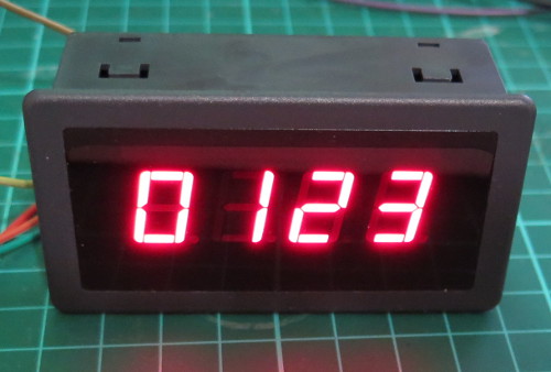
For example, to display “0123” you would use:
displayNumber(123, true);
… which results with:
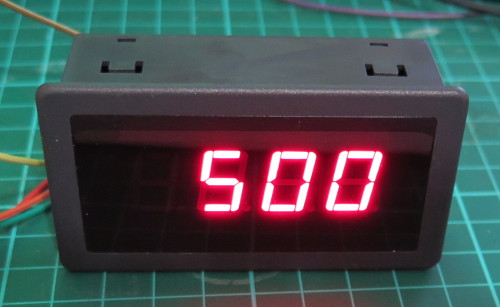
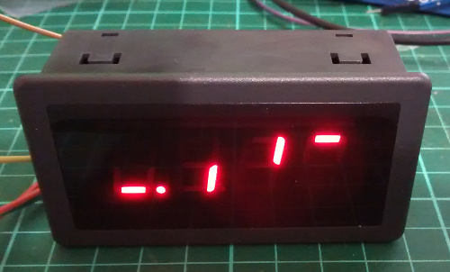
or to display “500” you would use:
displayNumber(500, false);
… which results with:
To turn off all the digits, you need to send zeros to every bit in the shift register, and this is accomplished with the function in the sketch called
allOff();
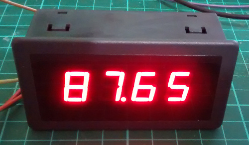
What about the decimal point?
To turn on the decimal point for a particular digit, add 1 to the value being sent to a particular digit. Using the code from the demonstration sketch to display 87.65 you would use:
In-depth explanation of how the module is controlled
As shown in the schematic above, each digit is controlled by a 74HC595 shift register. Each shift register has eight digital outputs, each of which control an individual segment of each digit. So by sending four bytes of data (one byte = eight bits) you can control each segment of the display.
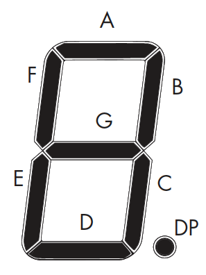
Each digit’s segments are mapped as follows:
And the outputs from each shift register match the order of segments from left to right. So outputs 0~7 match A~G then decimal point.
For example, to create the number seven with a decimal point, you need to turn on segments A, B, C and DP – which match to the shift register’s outputs 0,1,2,8.
Thus the byte to send to the shift register would be 0b11100001 (or 225 in decimal or 0xE1 in hexadecimal).
Every time you want to change the display you need to re-draw all four (or more if more than one module is connected) digits – so four bytes of data are sent for each display change. The digits are addressed from right to left, so the first byte send is for the last digit – and the last byte is for the first digit.
There are three stages of updating the display.
Set the LCK (latch) line low
Shift out four bytes of data from your microcontroller
Note how the bytes in binary match the map of the digits and their position. For example, the first byte sent was for the fourth digit, and the segment A was turned on. And that’s all there is to it – a neat and simple display.
This post brought to you by pmdway.com – everything for makers and electronics enthusiasts, with free delivery worldwide.
To keep up to date with new posts at tronixstuff.com, please subscribe to the mailing list in the box on the right, or follow us on twitter @tronixstuff.
Planet Arduino is, or at the moment is wishing to become, an aggregation of public weblogs from around the world written by people who develop, play, think on Arduino platform and his son. The opinions expressed in those weblogs and hence this aggregation are those of the original authors. Entries on this page are owned by their authors. We do not edit, endorse or vouch for the contents of individual posts. For more information about Arduino please visit www.arduino.cc
You are currently browsing the archives for the LED category.

 Inside the printed puck is an Arduino Nano running an MPU6050 accelerometer, a 12-NeoPixel ring, and a piezo buzzer. [DIY_Maxell] reused a power bank charging circuit to charge up the small LiPo battery.