Posts | Comments

Planet Arduino

Archive for the ‘colour’ Category

Learn how to use an inexpensive colour LCD shield with your Arduino. This is chapter twenty-eight of our huge Arduino tutorial series.

Updated 03/02/2014

There are many colour LCDs on the market that can be used with an Arduino, and for this tutorial we’re using a relatively simple model available that is available from suppliers such as Tronixlabs, based on a small LCD originally used in Nokia 6100 mobile phones:

Arduino Color LCD shield

These are a convenient and inexpensive way of displaying data, or for monitoring variables when debugging a sketch. Before getting started, a small amount of work is required.

From the two examples we have seen, neither of them arrive fitted with stacking headers (or in Sparkfun’s case – not included) or pins, so before doing anything you’ll need to fit your choice of connector. Although the LCD shield arrived with stacking headers, we used in-line pins as another shield would never be placed on top:

Arduino Color LCD shield fit headers

Which can easily be soldered to the shield in a few minutes:

Arduino Color LCD shield fitted

 While we’re on the subject of pins – this shield uses D3~D5 for the three buttons, and D8, 9, 11 and 13 for the LCD interface. The shield takes 5V and doesn’t require any external power for the backlight. The LCD module has a resolution of 128 x 128 pixels, with nine defined colours (red, green, blue, cyan, magenta, yellow, brown, orange, pink) as well as black and white.

So let’s get started. From a software perspective, the first thing to do is download and install the library for the LCD shield. Visit the library page here. Then download the .zip file, extract and copy the resulting folder into your ..arduino-1.0.xlibraries folder. Be sure to rename the folder to “ColorLCDShield“. Then restart the Arduino IDE if it was already open.

At this point let’s check the shield is working before moving forward. Once fitted to your Arduino, upload the ChronoLCD_Color sketch that’s included with the library, from the IDE Examples menu:

Arduino Color LCD shield example sketch

This will result with a neat analogue clock you can adjust with the buttons on the shield, as shown in this video.

It’s difficult to photograph the LCD – (some of them have very bright backlights), so the image may not be a true reflection of reality. Nevertheless this shield is easy to use and we will prove this in the following examples. So how do you control the color LCD shield in your sketches?

At the start of every sketch, you will need the following lines:

#include "ColorLCDShield.h"
LCDShield lcd;

as well as the following in void setup():

lcd.init(PHILIPS); 
lcd.contrast(63); // sets LCD contrast (value between 0~63)

With regards to lcd.init(), try it first without a parameter. If the screen doesn’t work, try EPSON instead. There are two versions of the LCD shield floating about each with a different controller chip. The contrast parameter is subjective, however 63 looks good – but test for yourself.

Now let’s move on to examine each function with a small example, then use the LCD shield in more complex applications.

The LCD can display 8 rows of 16 characters of text. The function to display text is:

lcd.setStr("text", y,x, foreground colour, background colour);

where x and y are the coordinates of the top left pixel of the first character in the string. Another necessary function is:

lcd.clear(colour);

Which clears the screen and sets the background colour to the parameter colour.  Please note – when referring to the X- and Y-axis in this article, they are relative to the LCD in the position shown below. Now for an example – to recreate the following display:

Arduino Color LCD shield text demonstration

… use the following sketch:

// Example 28.1
#include "ColorLCDShield.h"
LCDShield lcd;

void setup()
{
 // following two required for LCD
 lcd.init(PHILIPS); 
 lcd.contrast(63); // sets LCD contrast (value between 0~63)
}

void loop()
{
 lcd.clear(BLACK);
 lcd.setStr("ABCDefghiJKLMNOP", 0,2, WHITE, BLACK);
 lcd.setStr("0123456789012345", 15,2, WHITE, BLACK);
 lcd.setStr("ABCDefghiJKLMNOP", 30,2, WHITE, BLACK);
 lcd.setStr("0123456789012345", 45,2, WHITE, BLACK);
 lcd.setStr("ABCDefghiJKLMNOP", 60,2, WHITE, BLACK);
 lcd.setStr("0123456789012345", 75,2, WHITE, BLACK);
 lcd.setStr("ABCDefghiJKLMNOP", 90,2, WHITE, BLACK);
 lcd.setStr("0123456789012345", 105,2, WHITE, BLACK);
 do {} while (1>0);
}

In example 28.1 we used the function lcd.clear(), which unsurprisingly cleared the screen and set the background a certain colour.

Let’s have a look at the various background colours in the following example. The lcd.clear()  function is helpful as it can set the entire screen area to a particular colour. As mentioned earlier, there are the predefined colours red, green, blue, cyan, magenta, yellow, brown, orange, pink, as well as black and white. Here they are in the following example:

// Example 28.2

int del = 1000;
#include "ColorLCDShield.h"
LCDShield lcd; 
void setup() 
{ 
  // following two required for LCD 
  lcd.init(PHILIPS); 
  lcd.contrast(63); // sets LCD contrast (value between 0~63) 
}

void loop()
{
 lcd.clear(WHITE);
 lcd.setStr("White", 39,40, WHITE, BLACK);
 delay(del);
 lcd.clear(BLACK);
 lcd.setStr("Black", 39,40, WHITE, BLACK);
 delay(del);
 lcd.clear(YELLOW);
 lcd.setStr("Yellow", 39,40, WHITE, BLACK);
 delay(del);
 lcd.clear(PINK);
 lcd.setStr("Pink", 39,40, WHITE, BLACK);
 delay(del);
 lcd.clear(MAGENTA);
 lcd.setStr("Magenta", 39,40, WHITE, BLACK);
 delay(del);
 lcd.clear(CYAN);
 lcd.setStr("Cyan", 39,40, WHITE, BLACK);
 delay(del);
 lcd.clear(BROWN);
 lcd.setStr("Brown", 39,40, WHITE, BLACK);
 delay(del);
 lcd.clear(ORANGE);
 lcd.setStr("Orange", 39,40, WHITE, BLACK);
 delay(del);
 lcd.clear(BLUE);
 lcd.setStr("Blue", 39,40, WHITE, BLACK);
 delay(del);
 lcd.clear(RED);
 lcd.setStr("Red", 39,40, WHITE, BLACK);
 delay(del);
 lcd.clear(GREEN);
 lcd.setStr("Green", 39,40, WHITE, BLACK);
 delay(del);
}

And now to see it in action. In this demonstration video the colours are more livid in real life, unfortunately the camera does not capture them so well.


Now that we have had some experience with the LCD library’s functions, we can move on to drawing some graphical objects. Recall that the screen has a resolution of 128 by 128 pixels. We have four functions to make use of this LCD real estate, so let’s see how they work. The first is:

lcd.setPixel(int colour, Y, X);

This function places a pixel (one LCD dot) at location x, y with the colour of colour.

Note – in this (and all the functions that have a colour parameter) you can substitute the colour (e.g. BLACK) for a 12-bit RGB value representing the colour required. Next is:

lcd.setLine(x0, y0, x1, y1, COLOUR);

Which draws a line of colour COLOUR, from position x0, y0 to x1, y1. Our next function is:

lcd.setRect(x0, y0, x1, y1, fill, COLOUR);

This function draws an oblong or square of colour COLOUR with the top-left point at x0, y0 and the bottom right at x1, y1. Fill is set to 0 for an outline, and 1 for a filled oblong. It would be convenient for drawing bar graphs for data representation. And finally, we can also create circles, using:

lcd.setCircle(x, y, radius, COLOUR);

X and Y is the location for the centre of the circle, radius and COLOUR are self-explanatory. We will now use these graphical functions in the following demonstration sketch:

// Example 28.3

#include "ColorLCDShield.h"
LCDShield lcd;
int del = 1000;
int xx, yy = 0;

void setup()
{
  lcd.init(PHILIPS); 
  lcd.contrast(63); // sets LCD contrast (value between 0~63)
  lcd.clear(BLACK);
  randomSeed(analogRead(0));
}

void loop()
{
  lcd.setStr("Graphic Function", 40,3, WHITE, BLACK);
  lcd.setStr("Test Sketch", 55, 20, WHITE, BLACK); 
  delay(5000);
  lcd.clear(BLACK);
  lcd.setStr("lcd.setPixel", 40,20, WHITE, BLACK);
  delay(del);
  lcd.clear(BLACK);
  for (int a=0; a<500; a++)
  {
    xx=random(160);
    yy=random(160);
    lcd.setPixel(WHITE, yy, xx);
    delay(10);
  }
  delay(del);
  lcd.clear(BLACK);
  lcd.setStr("LCDDrawCircle", 40,10, WHITE, BLACK);
  delay(del);
  lcd.clear(BLACK); 
  for (int a=0; a<2; a++)
  {
    for (int b=1; b<6; b++)
    {
      xx=b*5;
      lcd.setCircle(32, 32, xx, WHITE);
      delay(200);
      lcd.setCircle(32, 32, xx, BLACK);
      delay(200);
    }
  }
  lcd.clear(BLACK); 
  for (int a=0; a<3; a++)
  {
    for (int b=1; b<12; b++)
    {
      xx=b*5;
      lcd.setCircle(32, 32, xx, WHITE);
      delay(100);
    }
    lcd.clear(BLACK);
  }
  lcd.clear(BLACK); 
  for (int a=0; a<3; a++)
  {
    for (int b=1; b<12; b++)
    {
      xx=b*5;
      lcd.setCircle(32, 32, xx, WHITE);
      delay(100);
    }
    lcd.clear(BLACK);
  }
  delay(del);
  lcd.clear(BLACK);
  lcd.setStr("LCDSetLine", 40,10, WHITE, BLACK);
  delay(del);
  lcd.clear(BLACK); 
  for (int a=0; a<160; a++)
  {
    xx=random(160);
    lcd.setLine(a, 1, xx, a, WHITE);
    delay(10);
  }
  lcd.clear(BLACK);
  lcd.setStr("LCDSetRect", 40,10, WHITE, BLACK);
  delay(del);
  lcd.clear(BLACK); 
  for (int a=0; a<10; a++)
  {
    lcd.setRect(32,32,64,64,0,WHITE);
    delay(200);
    lcd.clear(BLACK);
    lcd.setRect(32,32,64,64,1,WHITE);
    delay(200);
    lcd.clear(BLACK); 
  }
  lcd.clear(BLACK); 
}

The results of this sketch are shown in this video. For photographic reasons, I will stick with white on black for the colours.

So now you have an explanation of the functions to drive the screen – and only your imagination is holding you back.

Conclusion

Hopefully this tutorial is of use to you. and you’re no longer wondering “how to use a color LCD with Arduino”. They’re available from our tronixlabs store. And if you enjoyed this article, or want to introduce someone else to the interesting world of Arduino – check out my book (now in a third printing!) “Arduino Workshop”.

visit tronixlabs.com

Have fun and keep checking into tronixstuff.com. Why not follow things on twitterGoogle+, subscribe  for email updates or RSS using the links on the right-hand column, or join our forum – dedicated to the projects and related items on this website. Sign up – it’s free, helpful to each other –  and we can all learn something.
Apr
26

Learn how to use inexpensive ILI9325 colour TFT LCD modules in chapter fifty of a series originally titled “Getting Started/Moving Forward with Arduino!” by John Boxall – A tutorial on the Arduino universe. The first chapter is here, the complete series is detailed here.

Introduction

Colour TFT LCD modules just keep getting cheaper, so in this tutorial we’ll show you how to get going with some of the most inexpensive modules we could find. The subject of our tutorial is a 2.8″ 240 x 320 TFT module with the ILI9325 LCD controller chip. If you look in ebay this example should appear pretty easily, here’s a photo of the front and back to help identify it:

There is also the line “HY-TFT240_262k HEYAODZ110510″ printed on the back of the module. They should cost less than US$10 plus shipping. Build quality may not be job number one at the factory so order a few, however considering the cost of something similar from other retailers it’s cheap insurance. You’ll also want sixteen male to female jumper wires to connect the module to your Arduino.

Getting started

To make life easier we’ll use an Arduino library “UTFT” written for this and other LCD modules. It has been created by Henning Karlsen and can be downloaded from his website. If you can, send him a donation – this library is well worth it. Once you’ve downloaded and installed the UTFT library, the next step is to wire up the LCD for a test.

Run a jumper from the following LCD module pins to your Arduino Uno (or compatible):

  • DB0 to DB7 > Arduino D0 to D7 respectively
  • RD > 3.3 V
  • RSET > A2
  • CS > A3
  • RW > A4
  • RS > A5
  • backlight 5V > 5V
  • backlight GND > GND

Then upload the following sketch – Example 50.1. You should be presented with the following on your display:

If you’re curious, the LCD module and my Eleven board draws 225 mA of current. If that didn’t work for you, double-check the wiring against the list provided earlier. Now we’ll move forward and learn how to display text and graphics.

Sketch preparation

You will always need the following before void setup():

#include "UTFT.h"
UTFT myGLCD(ILI9325C,19,18,17,16); // for Arduino Uno

and in void setup():

myGLCD.InitLCD(orientation); 
myGLCD.clrScr();

with the former command, change orientation to either LANDSCAPE to PORTRAIT depending on how you’ll view the screen. You may need further commands however these are specific to features that will be described below. The function .clrScr() will clear the screen.

Displaying Text

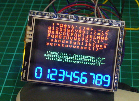
There are three different fonts available with the library. To use them add the following three lines before void setup():

extern uint8_t SmallFont[];
extern uint8_t BigFont[];
extern uint8_t SevenSegNumFont[];

When displaying text you’ll need to define the foreground and background colours with the following:

myGLCD.setColor(red, green, blue); 
myGLCD.setBackColor(red, green, blue);

Where red, green and blue are values between zero and 255. So if you want white use 255,255,255 etc. For some named colours and their RGB values, click here. To select the required font, use one of the following:

  myGLCD.setFont(SmallFont); // Allows 20 rows of 40 characters
  myGLCD.setFont(BigFont); // Allows 15 rows of 20 characters
  myGLCD.setFont(SevenSegNumFont); // allows display of 0 to 9 over four rows

Now to display the text use the function:

 myGLCD.print("text to display",x, y);

where text is what you’d like to display, x is the horizontal alignment (LEFT, CENTER, RIGHT) or position in pixels from the left-hand side of the screen and y is the starting point of the top-left of the text. For example, to start at the top-left of the display y would be zero. You can also display a string variable instead of text in inverted commas.

You can see all this in action with the following sketch – Example 50.2, which is demonstrated in the following video:

Furthremore, you can also specify the angle of display, which gives a simple way of displaying text on different slopes. Simply add the angle as an extra parameter at the end:

  myGLCD.print(“Hello, world”, 20, 20, angle);

Again, see the following sketch – Example 50.2a, and the results below:

Displaying Numbers

Although you can display numbers with the text functions explained previously, there are two functions specifically for displaying integers and floats.

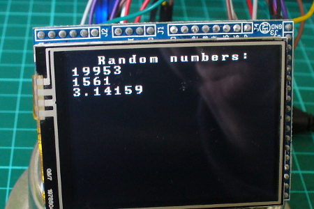
You can see these functions in action with the following sketch – Example 50.3, with an example of the results below:

example50p3

Displaying Graphics

There’s a few graphic functions that can be used to create required images. The first is:

myGLCD.fillScr(red, green, blue);

which is used the fill the screen with a certain colour. The next simply draws a pixel at a specified x,y location:

myGLCD.drawPixel(x,y);

Remember that the top-left of the screen is 0,0. Moving on, to draw a single line, use:

myGLCD.drawLine(x1,0,x2,239);

where the line starts at x1,y1 and finishes at x2,y2. Need a rectangle? Use:

myGLCD.drawRect(x1,y2,x2,y2); // for open rectangles
myGLCD.fillRect(x1,y2,x2,y2); // for filled rectangles

where the top-left of the rectangle is x1,y1 and the bottom-right is x2, y2. You can also have rectangles with rounded corners, just use:

myGLCD.drawRoundRect(x1,y2,x2,y2); // for open rectangles
myGLCD.fillRoundRect(x1,y2,x2,y2); // for filled rectangles

instead. And finally, circles – which are quite easy. Just use:

myGLCD.drawCircle(x,y,r); // draws open circle
myGLCD.fillCircle(x,y,r); // draws a filled circle

where x,y are the coordinates for the centre of the circle, and r is the radius. For a quick demonstration of all the graphic functions mentioned so far, see Example 50.4 – and the following video:

Displaying bitmap images

If you already have an image in .gif, .jpg or .png format that’s less than 300 KB in size, this can be displayed on the LCD. To do so, the file needs to be converted to an array which is inserted into your sketch. Let’s work with a simple example to explain the process. Below is our example image:

jrt3030

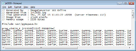
Save the image of the puppy somewhere convenient, then visit this page. Select the downloaded file, and select the .c and Arduino radio buttons, then click “make file”. After a moment or two a new file will start downloading. When it arrives, open it with a text editor – you’ll see it contains a huge array and another #include statement – for example:

cfile

Past the #include statement and the array into your sketch above void setup(). After doing that, don’t be tempted to “autoformat” the sketch in the Arduino IDE. Now you can use the following function to display the bitmap on the LCD:

myGLCD.drawBitmap(x,y,width,height, name, scale);

Where x and y are the top-left coordinates of the image, width and height are the … width and height of the image, and name is the name of the array. Scale is optional – you can double the size of the image with this parameter. For example a value of two will double the size, three triples it – etc. The function uses simple interpolation to enlarge the image, and can be a clever way of displaying larger images without using extra memory. Finally, you can also display the bitmap on an angle – using:

myGLCD.drawBitmap(x,y,width,height, name, angle, cx, cy);

where angle is the angle of rotation and cx/cy are the coordinates for the rotational centre of the image.

The bitmap functions using the example image have been used in the following sketch – Example 50.5, with the results in the following video:

Unfortunately the camera doesn’t really do the screen justice, it looks much better with the naked eye.

What about the SD card socket and touch screen?

The SD socket didn’t work, and I won’t be working with the touch screen at this time.

Conclusion

So there you have it – an incredibly inexpensive and possibly useful LCD module. Thank you to Henning Karlsen for his useful library, and if you found it useful – send him a donation via his page.

In the meanwhile have fun and keep checking into tronixstuff.com. Why not follow things on twitterGoogle+, subscribe  for email updates or RSS using the links on the right-hand column? And join our friendly Google Group – dedicated to the projects and related items on this website. Sign up – it’s free, helpful to each other –  and we can all learn something.


Learn how to use inexpensive ILI9325 colour TFT LCD modules in chapter fifty of a series originally titled “Getting Started/Moving Forward with Arduino!” by John Boxall – A tutorial on the Arduino universe. The first chapter is here, the complete series is detailed here.

Introduction

Colour TFT LCD modules just keep getting cheaper, so in this tutorial we’ll show you how to get going with some of the most inexpensive modules we could find. The subject of our tutorial is a 2.8″ 240 x 320 TFT module with the ILI9325 LCD controller chip. If you look in ebay this example should appear pretty easily, here’s a photo of the front and back to help identify it:

There is also the line “HY-TFT240_262k HEYAODZ110510″ printed on the back of the module. They should cost less than US$10 plus shipping. Build quality may not be job number one at the factory so order a few, however considering the cost of something similar from other retailers it’s cheap insurance. You’ll also want sixteen male to female jumper wires to connect the module to your Arduino.

Getting started

To make life easier we’ll use an Arduino library “UTFT” written for this and other LCD modules. It has been created by Henning Karlsen and can be downloaded from his website. If you can, send him a donation – this library is well worth it. Once you’ve downloaded and installed the UTFT library, the next step is to wire up the LCD for a test.

Run a jumper from the following LCD module pins to your Arduino Uno (or compatible):

  • DB0 to DB7 > Arduino D0 to D7 respectively
  • RD > 3.3 V
  • RSET > A2
  • CS > A3
  • RW > A4
  • RS > A5
  • backlight 5V > 5V
  • backlight GND > GND

Then upload the following sketch – Example 50.1. You should be presented with the following on your display:

If you’re curious, the LCD module and my Eleven board draws 225 mA of current. If that didn’t work for you, double-check the wiring against the list provided earlier. Now we’ll move forward and learn how to display text and graphics.

Sketch preparation

You will always need the following before void setup():

#include "UTFT.h"
UTFT myGLCD(ILI9325C,19,18,17,16); // for Arduino Uno

and in void setup():

myGLCD.InitLCD(orientation); 
myGLCD.clrScr();

with the former command, change orientation to either LANDSCAPE to PORTRAIT depending on how you’ll view the screen. You may need further commands however these are specific to features that will be described below. The function .clrScr() will clear the screen.

Displaying Text

There are three different fonts available with the library. To use them add the following three lines before void setup():

extern uint8_t SmallFont[];
extern uint8_t BigFont[];
extern uint8_t SevenSegNumFont[];

When displaying text you’ll need to define the foreground and background colours with the following:

myGLCD.setColor(red, green, blue); 
myGLCD.setBackColor(red, green, blue);

Where red, green and blue are values between zero and 255. So if you want white use 255,255,255 etc. For some named colours and their RGB values, click here. To select the required font, use one of the following:

myGLCD.setFont(SmallFont); // Allows 20 rows of 40 characters
myGLCD.setFont(BigFont); // Allows 15 rows of 20 characters
myGLCD.setFont(SevenSegNumFont); // allows display of 0 to 9 over four rows

Now to display the text use the function:

myGLCD.print("text to display",x, y);

where text is what you’d like to display, x is the horizontal alignment (LEFT, CENTER, RIGHT) or position in pixels from the left-hand side of the screen and y is the starting point of the top-left of the text. For example, to start at the top-left of the display y would be zero. You can also display a string variable instead of text in inverted commas.

You can see all this in action with the following sketch – Example 50.2, which is demonstrated in the following video:

Furthremore, you can also specify the angle of display, which gives a simple way of displaying text on different slopes. Simply add the angle as an extra parameter at the end:

myGLCD.print("Hello, world", 20, 20, angle);

Again, see the following sketch – Example 50.2a, and the results below:

Displaying Numbers

Although you can display numbers with the text functions explained previously, there are two functions specifically for displaying integers and floats.

You can see these functions in action with the following sketch – Example 50.3, with an example of the results below:

example50p3

Displaying Graphics

There’s a few graphic functions that can be used to create required images. The first is:.

myGLCD.fillScr(red, green, blue);

which is used the fill the screen with a certain colour. The next simply draws a pixel at a specified x,y location:

myGLCD.drawPixel(x,y);

Remember that the top-left of the screen is 0,0. Moving on, to draw a single line, use:

myGLCD.drawLine(x1,0,x2,239);

where the line starts at x1,y1 and finishes at x2,y2. Need a rectangle? Use:

myGLCD.drawRect(x1,y2,x2,y2); // for open rectangles
myGLCD.fillRect(x1,y2,x2,y2); // for filled rectangles

where the top-left of the rectangle is x1,y1 and the bottom-right is x2, y2. You can also have rectangles with rounded corners, just use:

myGLCD.drawRoundRect(x1,y2,x2,y2); // for open rectangles
myGLCD.fillRoundRect(x1,y2,x2,y2); // for filled rectangles

instead. And finally, circles – which are quite easy. Just use:

myGLCD.drawCircle(x,y,r); // draws open circle
myGLCD.fillCircle(x,y,r); // draws a filled circle

where x,y are the coordinates for the centre of the circle, and r is the radius. For a quick demonstration of all the graphic functions mentioned so far, see Example 50.4 – and the following video:

Displaying bitmap images

If you already have an image in .gif, .jpg or .png format that’s less than 300 KB in size, this can be displayed on the LCD. To do so, the file needs to be converted to an array which is inserted into your sketch. Let’s work with a simple example to explain the process. Below is our example image:

jrt3030

Save the image of the puppy somewhere convenient, then visit this page. Select the downloaded file, and select the .c and Arduino radio buttons, then click “make file”. After a moment or two a new file will start downloading. When it arrives, open it with a text editor – you’ll see it contains a huge array and another #include statement – for example:

cfile

Past the #include statement and the array into your sketch above void setup(). After doing that, don’t be tempted to “autoformat” the sketch in the Arduino IDE. Now you can use the following function to display the bitmap on the LCD:

myGLCD.drawBitmap(x,y,width,height, name, scale);

Where x and y are the top-left coordinates of the image, width and height are the … width and height of the image, and name is the name of the array. Scale is optional – you can double the size of the image with this parameter. For example a value of two will double the size, three triples it – etc. The function uses simple interpolation to enlarge the image, and can be a clever way of displaying larger images without using extra memory. Finally, you can also display the bitmap on an angle – using:

myGLCD.drawBitmap(x,y,width,height, name, angle, cx, cy);

where angle is the angle of rotation and cx/cy are the coordinates for the rotational centre of the image.

The bitmap functions using the example image have been used in the following sketch – Example 50.5, with the results in the following video:

Unfortunately the camera doesn’t really do the screen justice, it looks much better with the naked eye.

What about the SD card socket and touch screen?

The SD socket didn’t work, and I won’t be working with the touch screen at this time.

Conclusion

So there you have it – an incredibly inexpensive and possibly useful LCD module. Thank you to Henning Karlsen for his useful library, and if you found it useful – send him a donation via his page.

LEDborder

In the meanwhile have fun and keep checking into tronixstuff.com. Why not follow things on twitterGoogle+, subscribe  for email updates or RSS using the links on the right-hand column? And join our friendly Google Group – dedicated to the projects and related items on this website. Sign up – it’s free, helpful to each other –  and we can all learn something.

The post Tutorial – Arduino and ILI9325 colour TFT LCD modules appeared first on tronixstuff.

Jun
11

Kit Review – akafugu TWILCD Display Controller Backpacks

40x2, 40x4, akafugu, arduino, backpack, colour, i2c, kit review, LCD, lesson, part review, review, RGB, tronixstuff, tutorial, twilcd Comments Off on Kit Review – akafugu TWILCD Display Controller Backpacks 

Introduction

Working with LCD displays is always useful, for debugging hardware by showing various data or part of a final design. Furthermore, using them can be rather wasteful of I/O pins, especially when trying to squeeze in other functionality. Plus there’s the external contrast adjustment, general wiring and the time taken to get it working. (Don’t believe me? See here).

However, using the subjects of this kit review – you can convert standard HD44780 LCD modules to use the I2C bus using a small backpack-style board – bringing total I/O down to four wires – 5V/3.3V, GND, SDA and SCL. If you’re using an Arduino – don’t panic if you’re not up on I2C – a software library takes care of the translation leaving you to use the LiquidCrystal functions as normal. Furthermore you can control the brightness and contrast (and colour for RGB modules) – this feature alone is just magic and will make building these features into projects much, much easier.

In this review we examine both of the backpacks available from akafugu. There are two available:

  • the TWILCD: Supports 1×16 and 2×7 connectors. It covers 16×1, 20×1, 16×2, 20×2 and 20×4 displays with and without backlight, and the
  • TWILCD 40×2/40×4/RGB: Supports 1×18 connector (for Newhaven RGB backlit displays), 2×8 connector (used for some 20×4 displays) and 2×9 connector (used for 40×4 displays)
If unsure about your LCD, see the list and explanation here. The LCDs used in this article were supplied with the mono and colour LCD bundles available from akafugu. So let’s see how easy they really are, and put them through their paces.

Assembly

The backpacks arrive in the usual anti-static bags:

First we’ll examine the TWILCD board:

Very small indeed. There are three distinct areas of interface – including the single horizontal or dual vertical connectors for various LCDs, and I2C bus lines as well as ICSP connectors for the onboard ATTINY4313 microcontroller. The firmware can be updated and is available on the akafugu github repository. If you look at the horizontal row along the top – there are eighteen holes. This allows for displays that have pins ordered 1~16 and also those with 15,16,1~16 order (15 and 16 are for the LCD backlight).

The next step is to solder in the connectors for power and I2C if so desired, and then the LCD to the backpack. Double-check that you have the pin numbering and alignment correct before soldering, for example:

and then you’re finished:

Simple. Now apply power and after a moment the the backpack firmware will display the I2C bus address:

Success! Now let’s repeat this with the TWILCD 40×2/40×4/RGB version. The backpack itself is still quite small:

… and has various pin alignments for different types of LCD module. Note the extra pins allowing use of RGB-backlit modules and 40×4 character modules. Again,  make sure you have the pins lined up against your LCD module before soldering the backpack in:

 Notice how the I2C connector is between the LCD and the backpack – there is enough space for it to sit in there, and also acts as a perfect spacer when soldering the backpack to the display module.  Once finished soldering, apply 5/3.3V and GND to check your display:

Using the TWILCDs

Using the backpacks is very easy. If you aren’t using an Arduino, libraries for AVR-GCC are available. If you are using the Arduino system, it is very simple. Just download and install the library from here. Don’t forget to connect the SDA and SCL connectors to your Arduino. If you’re unsure about LCD and Arduino – see here.

Programming for the TWILCD is dead simple – just use your existing Arduino sketch, but replace

#include <LiquidCrystal.h>

with

#include <Wire.h>
#include <TWILiquidCrystal.h>

and that’s it. Even creating custom characters. No new functions to learn or tricks to take note of – they just work. Total win. The only new functions you will need are to control the brightness and contrast… to set the brightness, use:

lcd.setBrightness(brightness);

You can also set the brightness level to EEPROM as a default using:

lcd.saveBrightness([YOUR_VALUE])

Contrast is equally simple, using:

lcd.setContrast(contrast);

and

lcd.saveContrast([YOUR_VALUE])

You can see these in action using the example sketches with the Arduino library, and in the following video:

Now for the TWILCD 40×2/40×4/RGB version. You have one more function to set the colour of the text:

lcd.setColor(red, green, blue);

where red, green and blue are values between 0 and 254. Easily done. You can see this in action using the test_RGB example sketch included with the library, and shown in the following video:

Conclusion

The TWILCD backpacks are simple, easy to setup and easy to use. They make using LCD displays a lot easier and faster for rapid prototyping, experimenting or making final products easier to use and program. A well-deserved addition to every experimenter’s toolkit. For more information, visit the akafugu product website. Full-size images available on flickr.

Note – the products used in this article were a promotional consideration from akafugu.jp, however the opinions stated are purely my own.

In the meanwhile have fun and keep checking into tronixstuff.com. Why not follow things on twitterGoogle+, subscribe  for email updates or RSS using the links on the right-hand column? And join our friendly Google Group – dedicated to the projects and related items on this website. Sign up – it’s free, helpful to each other –  and we can all learn something.

Translated version in Serbo-Croatian language.


Jun
11

Kit Review – akafugu TWILCD Display Controller Backpacks

40x2, 40x4, akafugu, arduino, backpack, clocks, colour, i2c, kit review, LCD, lesson, part review, review, RGB, tronixstuff, tutorial, twilcd Comments Off on Kit Review – akafugu TWILCD Display Controller Backpacks 

Introduction

Working with LCD displays is always useful, for debugging hardware by showing various data or part of a final design. Furthermore, using them can be rather wasteful of I/O pins, especially when trying to squeeze in other functionality. Plus there’s the external contrast adjustment, general wiring and the time taken to get it working. (Don’t believe me? See here).

However, using the subjects of this kit review – you can convert standard HD44780 LCD modules to use the I2C bus using a small backpack-style board – bringing total I/O down to four wires – 5V/3.3V, GND, SDA and SCL. If you’re using an Arduino – don’t panic if you’re not up on I2C – a software library takes care of the translation leaving you to use the LiquidCrystal functions as normal. Furthermore you can control the brightness and contrast (and colour for RGB modules) – this feature alone is just magic and will make building these features into projects much, much easier.

In this review we examine both of the backpacks available from akafugu. There are two available:

  • the TWILCD: Supports 1×16 and 2×7 connectors. It covers 16×1, 20×1, 16×2, 20×2 and 20×4 displays with and without backlight, and the
  • TWILCD 40×2/40×4/RGB: Supports 1×18 connector (for Newhaven RGB backlit displays), 2×8 connector (used for some 20×4 displays) and 2×9 connector (used for 40×4 displays)
If unsure about your LCD, see the list and explanation here. The LCDs used in this article were supplied with the mono and colour LCD bundles available from akafugu. So let’s see how easy they really are, and put them through their paces.

Assembly

The backpacks arrive in the usual anti-static bags:

First we’ll examine the TWILCD board:

Very small indeed. There are three distinct areas of interface – including the single horizontal or dual vertical connectors for various LCDs, and I2C bus lines as well as ICSP connectors for the onboard ATTINY4313 microcontroller. The firmware can be updated and is available on the akafugu github repository. If you look at the horizontal row along the top – there are eighteen holes. This allows for displays that have pins ordered 1~16 and also those with 15,16,1~16 order (15 and 16 are for the LCD backlight).

The next step is to solder in the connectors for power and I2C if so desired, and then the LCD to the backpack. Double-check that you have the pin numbering and alignment correct before soldering, for example:

and then you’re finished:

Simple. Now apply power and after a moment the the backpack firmware will display the I2C bus address:

Success! Now let’s repeat this with the TWILCD 40×2/40×4/RGB version. The backpack itself is still quite small:

… and has various pin alignments for different types of LCD module. Note the extra pins allowing use of RGB-backlit modules and 40×4 character modules. Again,  make sure you have the pins lined up against your LCD module before soldering the backpack in:

 Notice how the I2C connector is between the LCD and the backpack – there is enough space for it to sit in there, and also acts as a perfect spacer when soldering the backpack to the display module.  Once finished soldering, apply 5/3.3V and GND to check your display:

Using the TWILCDs

Using the backpacks is very easy. If you aren’t using an Arduino, libraries for AVR-GCC are available. If you are using the Arduino system, it is very simple. Just download and install the library from here. Don’t forget to connect the SDA and SCL connectors to your Arduino. If you’re unsure about LCD and Arduino – see here.

Programming for the TWILCD is dead simple – just use your existing Arduino sketch, but replace

#include "LiquidCrystal.h"

with

#include "Wire.h"
#include "TWILiquidCrystal.h"

and that’s it. Even creating custom characters. No new functions to learn or tricks to take note of – they just work. Total win. The only new functions you will need are to control the brightness and contrast… to set the brightness, use:

lcd.setBrightness(brightness);

You can also set the brightness level to EEPROM as a default using:

lcd.saveBrightness([YOUR_VALUE])

Contrast is equally simple, using:

lcd.setContrast(contrast);

and
lcd.saveContrast([YOUR_VALUE]);

You can see these in action using the example sketches with the Arduino library, and in the following video:

Now for the TWILCD 40×2/40×4/RGB version. You have one more function to set the colour of the text:

lcd.setColor(red, green, blue);

where red, green and blue are values between 0 and 254. Easily done. You can see this in action using the test_RGB example sketch included with the library, and shown in the following video:

Conclusion

The TWILCD backpacks are simple, easy to setup and easy to use. They make using LCD displays a lot easier and faster for rapid prototyping, experimenting or making final products easier to use and program. A well-deserved addition to every experimenter’s toolkit. For more information, visit the akafugu product website. Full-size images available on flickr.

Note – the products used in this article were a promotional consideration from akafugu.jp, however the opinions stated are purely my own.

In the meanwhile have fun and keep checking into tronixstuff.com. Why not follow things on twitterGoogle+, subscribe  for email updates or RSS using the links on the right-hand column? And join our friendly Google Group – dedicated to the projects and related items on this website. Sign up – it’s free, helpful to each other –  and we can all learn something.

Translated version in Serbo-Croatian language.

The post Kit Review – akafugu TWILCD Display Controller Backpacks appeared first on tronixstuff.


  • Newsletter

    Sign up for the PlanetArduino Newsletter, which delivers the most popular articles via e-mail to your inbox every week. Just fill in the information below and submit.

  • Like Us on Facebook