Traditional bi-directional wireless communication requires both a receiver and a transmitter at either end. Your laptop, for example, needs to receive a signal from your Wi-Fi router, but it also needs to transmit a signal back to that router. That transmission requires power proportional to the strength of the signal, which is less than ideal for many applications. Backscatter provides an alternative and Uniscatter is new backscatter technology developed by a team of UC San Diego engineers that promises cost-effective reliability.
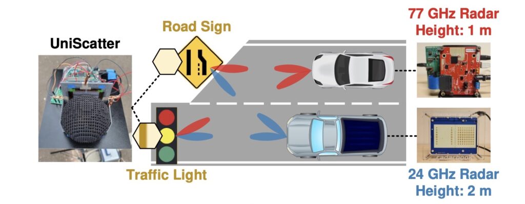
Backscatter communication works by reflecting a signal emitted by the receiver. But in order for that reflected signal to carry information, the reflector (the backscatter “tag”) needs to be able to introduce some form of modulation. That might information might be as simple as a static identifier, but it can be dynamic as well. A self-driving car could, for example, read backscatter tags on road signs with information as simple as a speed limit or something more complex like the state of a traffic light.
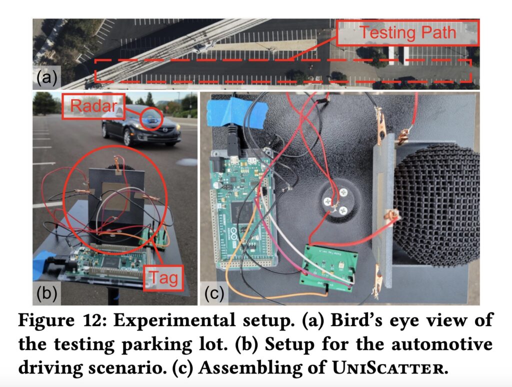
Uniscatter utilizes metamaterials, like graphene, to provide more reliable backscatter reflections. It also utilizes frequency shift keying (FSK), as opposed to amplitude shift keying (ASK), for modulation. For that to work, the Uniscatter tag needs to alter the voltage bias of the graphene capacitor to control the backscatter reflection. Uniscatter’s developers used an Arduino Due board to provide that modulation control.
In their research, Uniscatter’s developers determined that this system works reliably from 20GHz to 90GHz. That allows for a lot of flexibility in system design and also ensures that communication remains stable across a wide variety of ambient conditions and physical orientations.
Traditional bi-directional wireless communication requires both a receiver and a transmitter at either end. Your laptop, for example, needs to receive a signal from your Wi-Fi router, but it also needs to transmit a signal back to that router. That transmission requires power proportional to the strength of the signal, which is less than ideal for many applications. Backscatter provides an alternative and Uniscatter is new backscatter technology developed by a team of UC San Diego engineers that promises cost-effective reliability.
Backscatter communication works by reflecting a signal emitted by the receiver. But in order for that reflected signal to carry information, the reflector (the backscatter “tag”) needs to be able to introduce some form of modulation. That might information might be as simple as a static identifier, but it can be dynamic as well. A self-driving car could, for example, read backscatter tags on road signs with information as simple as a speed limit or something more complex like the state of a traffic light.
Uniscatter utilizes metamaterials, like graphene, to provide more reliable backscatter reflections. It also utilizes frequency shift keying (FSK), as opposed to amplitude shift keying (ASK), for modulation. For that to work, the Uniscatter tag needs to alter the voltage bias of the graphene capacitor to control the backscatter reflection. Uniscatter’s developers used an Arduino Due board to provide that modulation control.
In their research, Uniscatter’s developers determined that this system works reliably from 20GHz to 90GHz. That allows for a lot of flexibility in system design and also ensures that communication remains stable across a wide variety of ambient conditions and physical orientations.
Many types of medications (such as anti-depressants like SSRIs) can have a very negative effect if they aren’t taken on a regular basis. Even taking them a few hours late can harm a person’s mood and cause physical discomfort. But remembering to take pills at the proper time can be tricky — even setting an alarm isn’t foolproof, because you can turn it off without actually taking a pill. That’s why M. Bindhammer is building a 3D-printed robotic pill dispenser that will tell people if they forget to take their medicine.
M. Bindhammer’s design reflects his own needs: he has to take one pill in the morning and another in the evening. He suffers from bipolar disorder and missing the schedule by even a couple of hours can have consequences. To ensure that he adheres to that schedule, this robot dispenses two pills a day and will demand attention if M. Bindhammer forgets. It has 14 chambers, so M. Bindhammer can load up a full week’s worth of medication at once for convenient long-term use.
While the project isn’t complete yet, M. Bindhammer has finished the mechanical design and worked out most of the circuitry. The 14 chambers sit around a wheel torso turned by a continuous rotation servo motor, with a second servo motor that opens a door underneath the current chamber to allow a pill to drop down. An Arduino Due board with a custom breakout shield — which also integrates a DS3231 precision RTC — controls those servos and monitors a capacitive touch sensor in the base so it knows when the user picks up a pill. The Arduino will be able to provide feedback through an OLED screen face and a speaker connected to a speech synthesis module. When the robot is done, those will let the Arduino display a warning and emit an audio reminder if M. Bindhammer doesn’t take a pill when he should.
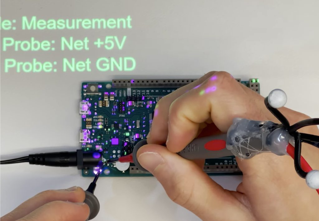
Imagine if you could identify a component and its schematic label by simply touching that component on your PCB. Imagine if you selected a pin in KiCAD and it started glowing on your real, physical PCB so you can find it easily. Imagine if you could see through your PCB’s solder mask to view the traces underneath. All of those things — and much more — are possible with this Augmented Reality Debugging Workbench (ARDW) system.
ARDW pairs tracking camera computer vision with projection mapping for fantastic augmented reality examination of PCBs. Touch a component with the special probes and ARDW will project the component’s name and label onto the table next to your board. Select a component or a component’s pin in KicAD and ARDW will project a highlighted overlay on the physical board showing you where it is. ARDW can even guide you through automated debugging by highlighting probe points and checking your measurements as you take them.
The team that developed ARDW demonstrated the system using Arduino Uno and Arduino Due boards, which were ideal choices because they’re open source and schematics are readily available. But ARDW can work with any PCB for which the user possesses design files.
It works with a plugin for KiCAD, which is open source PCB design software popular in the maker community and industry. Through KiCAD, ARDW gains access to the PCB layout and the schematics. It matches those up with the physical board sitting on the workbench and then projects graphics according to the selection and the board’s location. ARDW is extremely useful for all kinds of development, debugging, and quality control tasks.
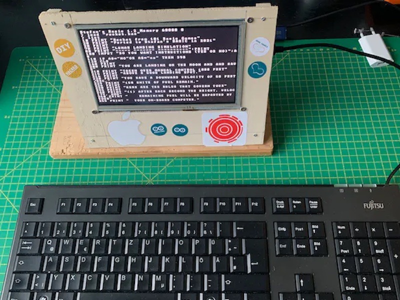
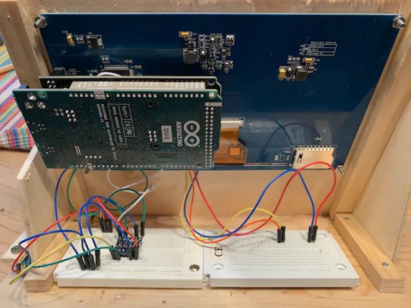
As a continuation from his previous Arduino BASIC interpreter project, Stefan Lenz wanted to take things a step further by recreating a home computer from the 1980s with an Arduino Due board and just a few other components. His system combines a 7″ 800 by 480px TFT screen with an SD card reader acting as the disk, along with a PS/2 port for connecting a keyboard.
He began by mounting the TFT display shield to the Arduino by slotting it in place and inserting an SD card to function as the external disk since floppy drives have long since disappeared and would be far too unwieldy. After soldering some additional wires to the SPI and I2C bus pins, a level shifter was attached to two digital pins that serve as the data and clock lines for the external PS/2 port.
Most of the “magic” in this project comes from the programming which handles everything from reading inputs to showing graphics on the LCD and even interfacing with other peripherals over either I2C or SPI. All of the code needed for this retro home computer can be found here in Lenz’s tinybasic repository, which contains a plethora of example projects and demonstrations that can be run/modified.
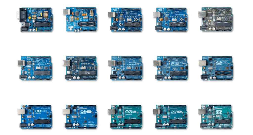
As familiar as we all are with the UNO, there’s probably a lot you don’t know about the iconic Arduino microcontroller board. Put on your rose-tinted spectacles, and let’s wax poetic about the origins of this beloved maker board.
Rise of the Techno-Hippies
By 2009, the team that would become Arduino was gathering steam. A team that Make: Magazine once referred to as “designers, teachers, artists, and techno-hippies.”
I don’t think anyone on that team would object to such a definition.
Forged in the crucible of a classroom, the idea of an accessible, affordable electronics development platform was under serious investigation. It would eventually give birth to the Arduino UNO, but despite its name meaning “one,” this is far from Arduino’s first board. Moreover, its name was chosen to mark a point in Arduino’s story where the business itself came out of beta and into version 1.0.
“The UNO is an arrival point of a large number of small experimentations and incremental improvements,” says co-founder Massimo Banzi.
These experiments weren’t just a learning experience for electronics design. They were useability tests, and even marketplace research. Each little quirk, unexpectedly popular feature and, of course, mistake helped to define what makers wanted and needed.
This was a time when the maker movement was still unrepresented by a defining brand or killer product. But not for long.
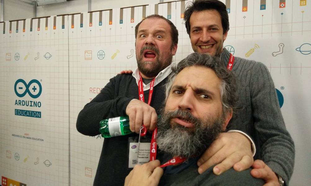
Massimo and David with Arduino CEO, Fabio Violante
Driving Towards the Future
The journey to the UNO wasn’t short, but it did have a distinct destination. The notion of an enhanced user experience was very prominent, although the people who would become the founders of Arduino hadn’t necessarily articulated it even to themselves. Looking back, it’s easy to see that this guiding principle was there from the beginning.
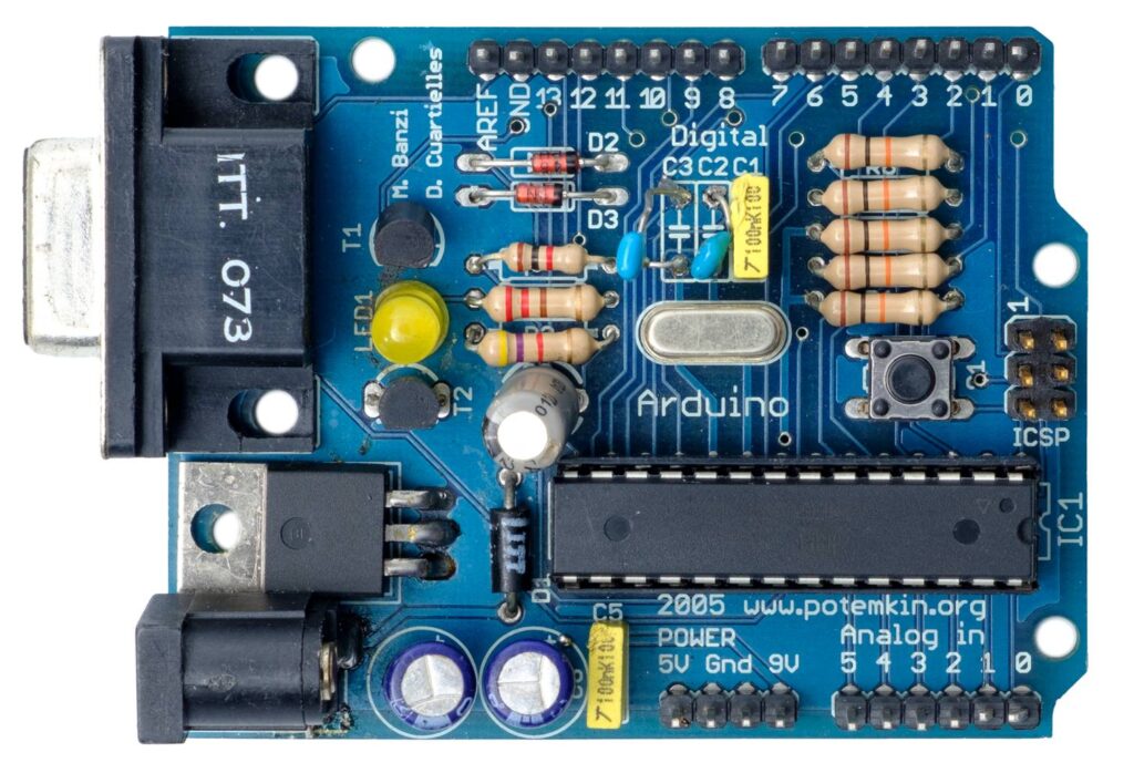
“On the original Arduino serial board, look at the components,” says co-founder David Cuartielles, talking about the earliest of Arduino’s self-assembly boards, which were used almost exclusively in the classroom. “They’re sorted by value. I made sure that components of a similar type and value were together, to minimize mistakes during assembly. For example, there were two diodes. In terms of operation, they’re working in opposite directions to each other. But to reduce errors when populating the board by hand, I set the diodes facing in the same direction, and the PCB’s tracks take care of orientation. So it’s optimized for education, not for electronic operation!”
“Back in the day we used to use FTDI chips,” Massimo recalls. “A Scottish company, now in Singapore. Great chips, but you had to install drivers to get your computer to recognize devices when you plugged them in.”
“Which is when we realized there was this thing called CDC (communications device class) protocol, which was embedded into operating systems. It’s the reason you don’t need a driver for a USB serial port. We found that you could develop a firmware for some simple Atmel processors that worked just the same as FTDI chips, but would liberate us from needing a driver.”
This opened the door to reprogramming the firmware and making the boards do other things. Some people created MIDI firmware to send notes to a computer. Others made HID firmware so they could emulate computer peripherals. It was the herald of dual processor experimentation, which piqued the interest of both Arduino users and its designers.
Press On with the UNO
These proto-UNOs also required you to press a reset button before uploading new code. It was a pretty standard requirement for any prototyping platform at the time. Most designers had simply never questioned this apparent necessity. But when the Arduino team found themselves placing more and more emphasis on user experience, this small requirement was identified as an obstacle to useability.
It was at a workshop in Germany when Massimo figured out an alternative.
“It turned out that if you put a capacitor between the reset pin of the microcontroller and one of the serial port pins,” he explains, “it would reset the board automatically whenever you opened the port.” This small tweak became a vital and very popular aspect of the UNO’s useability.
But there were a lot of other factors that went into making the UNO so recognizable that it’s become indistinguishable from the overall Arduino brand.
The Power of One
Early Arduino boards required a more active participation when it came to powering them up.
They already offered flexibility in choosing your power source. But if you wanted to power the board from the USB or the external power jack, you had to move a jumper. Not a lot to ask, but as many of the design experiments proved, these seemingly insignificant requirements had a disproportionate effect on usability.
People would forget to set the jumper in the first place. Or have it in the wrong position when trying to power on, and frustrations ensued. So a small circuit was implemented that detected where the power was coming from, and switched to it automatically. Simple, but essential.
Tweaks to the power options didn’t stop there. On other boards there had been some experimentation with microUSB ports, not realizing how fragile they can be. So when it came to the UNO, the USB connector was carefully chosen for its reliability. “It’s like a Russian tank,” Massimo laughs. “It’s indestructible.”
Feeling Blue
“Going from the original design we had on a rectangular green board, to the shaped blue board that everyone recognizes now, took two days,” David recalls, musing on how Arduino could move so fast because of its focus on simplicity. “And in between we went to a party. Because the designs are very simple.”
“The original board, before it became the Arduino UNO, was a typical green PCB,” Massimo explains, lavishing mediocrity on the state of pre-Arduino prototyping platforms. “Not so exciting. The PCB manufacturer we were talking to went on and on about how he was making blue PCBs because they were apparently easier on the eye for production line workers. We thought, ‘Hey! Blue is better, because everyone else is using green!’”
You can see a pattern in the way Arduino was beginning to question the norms of its industry. Those shades of blue and teal have become synonymous with Arduino devices, and that didn’t happen by accident. At the time, PCBs were green. Maybe beige, if they were still bare fibreglass.
But no longer, once the UNO arrived.
Arduino didn’t just have its eye fixed on usability. It was also searching for an identity that makers would associate with enhanced experience and quality. It just so happened that the UNO was destined to become the vessel that gave that identity a tangible shape.
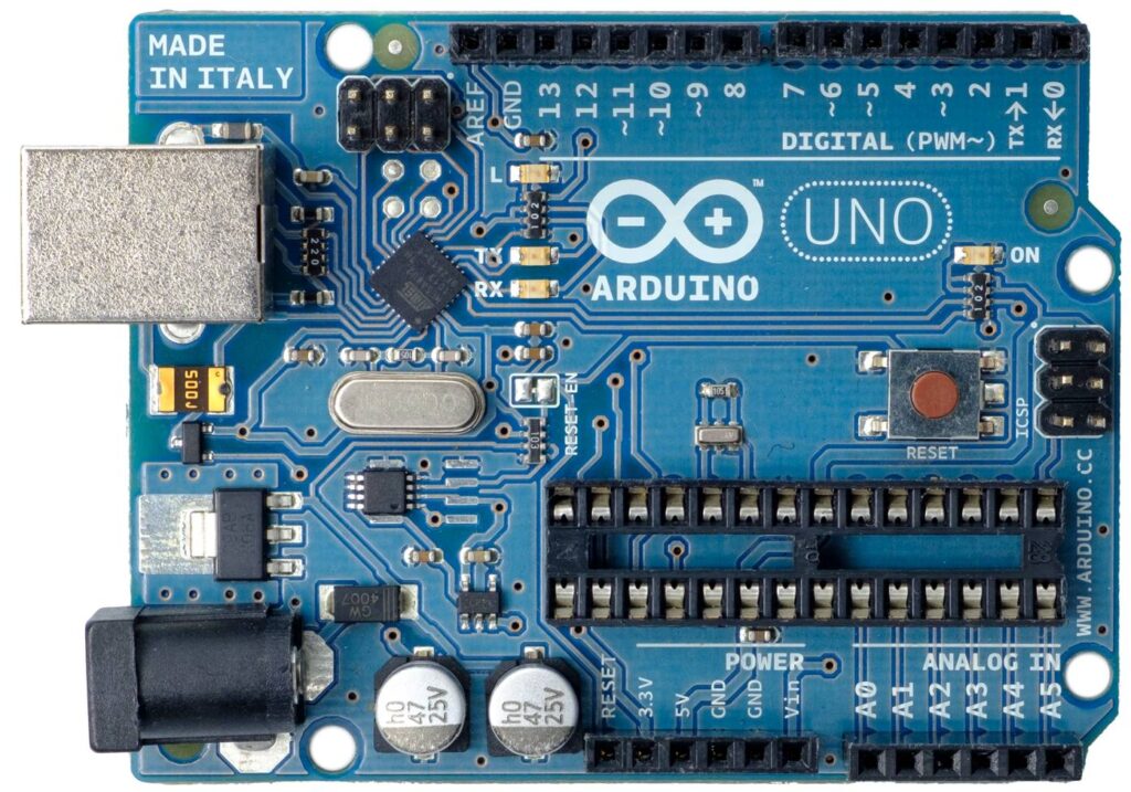
The beautiful blue board, with the first appearance of the brand new Arduino logo
Taking Shape
“I was teaching and I had to draw PCBs on a white board all the time,” recalls David. “And all boards were square or rectangular. So how do you tell people which is left and which is right? In order to avoid errors in plugging things in and building the boards, which originally were self-assembly, I thought it needed to be a non-symmetrical shape. Then the students could see that this is left and this is right. It wasn’t a creative decision, so much as a functional one for education purposes.”
Around that same time, the school where he was teaching in Ivrea was issuing everyone with business cards. They arrived on Massimo’s desk in a small plastic box. “So that seemed like a good starting place for sizing,” Massimo remembers, “as it seemed like a great idea if we could fit the UNO in a plastic box like the one my business cards came in.”
It was taking shape as a very recognizable product. And you want to put your name on products you’re proud of. Typically any branding on a PCB was added using the standard font that came with the Eagle PCB design software. Essentially vector lines, not graphics. This change was enacted by a former student of the Ivrea classroom, Giorgio Olivero. He was entrusted with the new Arduino identity.
“The strength of our current image depends entirely on the outstanding work Giorgio’s done,” David notes. “Giorgio understands not only graphic design, but the importance of designing the whole user experience. He understood interaction design really well. He understood the nature of the Arduino project intimately, and the needs of the end user.”
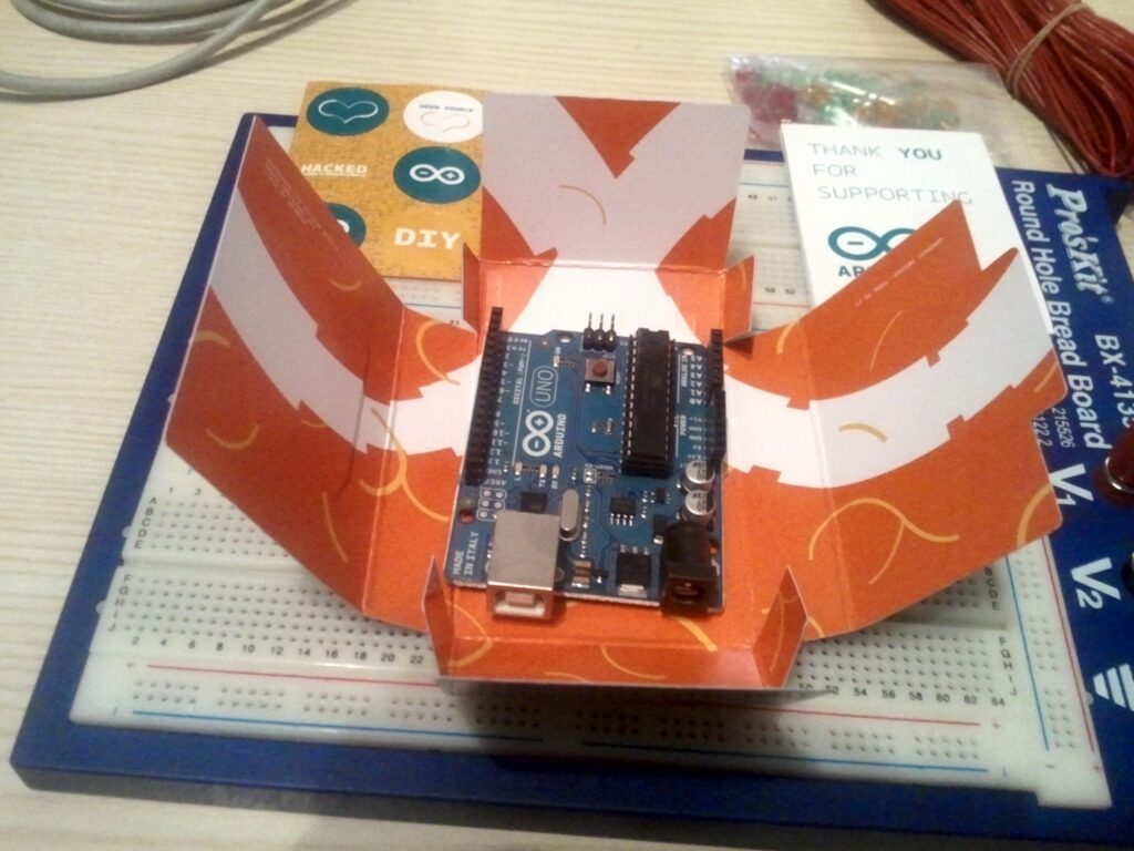
An UNO in its original packaging, designed by Giorgio Olivero. Photo courtesy of Francesco Balducci.
The UNO was the moment when quality came home in every respect. The boards were given an appealing new color, precision engineering, high quality manufacturing, and an emblem that made sure you knew you were holding an Arduino.
“The response was fantastic,” David continues, reflecting on the reception that the new Arduino and its flagship device received. “Nowadays it’s really common to do these kinds of things, but back then on the maker scene it was really unusual to put so much into making things look good, and putting a focus on the user experience.”
One Small Mistake
“When I was designing the board I made a mistake that we still have to live with,” admits Massimo. “I moved the connectors in the top right of the board half a step to the left, so the gap between the connectors is non-standard. It’s 1.27mm out. Which is fine on the connectors at the bottom, but that’s why you struggle to use a veroboard to develop shields, because the connectors aren’t quite aligned as they were meant to be.”
It’s a mistake that had a silver lining, though. That slight misalignment also (inadvertently, perhaps) gave us a key for attaching shields the right way around. So, just between you and me, let’s pretend it was deliberate and say no more about it.
Even the first batch of UNOs that came off the production line weren’t quite where Arduino wanted them to be, quality wise. The process for milling the PCBs into the iconic UNO shape wasn’t as reliable as it is now.
A small number of the boards had rough edges where they were snapped out of the sheet after cutting. Nothing that affected the operation of the board, but not so good when your focus is on achieving a distinctive level of quality.
“A friend and I spent the weekend at the PCB manufacturers,” Massimo remembers, semi-fondly, “sandpapering the edges of the first batch of UNO boards. What else could we do?”
Ten Thousand and UNO
Makers responded very positively to the ethos behind the UNO. And that enthusiasm was directly reflected in the number of Arduino boards sold.
“I remember an article in a magazine celebrating that Arduino had sold 10,000 boards,” Massimo recalls. “Arduino was here to stay, they said, because back then if anyone sold 10,000 boards you were boss!”
Arduino itself celebrated this milestone back in 2007, with a predecessor to the UNO called the Arduino Diecimila, meaning “ten thousand”. Interestingly enough, this was also the board that introduced automatic software resets when uploading a sketch, so you no longer had to press a reset button. Without the Diecimila, the UNO couldn’t have been born.
The Arduino Diecimila
Now Arduino’s selling in the region of 10,000 boards a week. As you can imagine, magazines and blogs have stopped writing about every maker device that hits the 10,000 milestone now. The UNO itself, in fact, has recently crossed the 10 million mark.
The Day of the UNO
It wasn’t just the Arduino UNO that was unveiled at the Maker Faire New York in 2010. It was the new Arduino. Colors, branding, logos and a refined focus on usability and recognizable quality across everything Arduino did, from the UNO to the website and the packaging.
“I was the only one not present at that event in New York,” David laughs. “I was in a hotel in my home town of Malmö, because I had to launch the new website. At the time we were running the whole Arduino server in a $5-per-month VPS, because we had no money. Whenever we announced a new product, the website was going down. So to try and avoid this happening while Massimo was up on stage announcing the Arduino UNO, I was waiting to flip the website to Giorgio’s fantastic new design.”
The UNO’s launch signaled a transition from DIY success story to the primary platform for makers, engineers and creators around the world.
“We didn’t create a computer that allowed people to continue to do their job but at a cheaper price,” David continues. “We created a computer that empowered people who had no idea about electronics to start using technology, and this represented a huge life change for a lot of people. When I hear people say they started with an Arduino UNO, and now they’ve become the IT teacher at their school, it’s just amazing. And there are hundreds of stories like this.”
“There are some products in history that just work,” Massimo concludes. “That simply do what people need. So they endure. They last for a long time.”
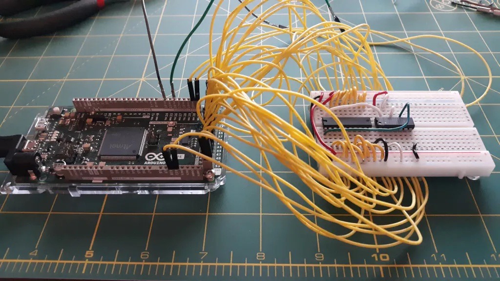
Breadboards are the first tool you break out in any prototyping journey and almost every project will utilize a breadboard at some point. Those breadboards often turn into a rats’ nest of overlapping wires that are difficult to trace, which makes it difficult to create an accurate schematic when it is time to design your PCB. To make your life easier, Nick Bild came up with a script that analyzes your physical breadboard to automatically generate a KiCAD schematic.
A breadboard is, at its core, a series of connectors. This script’s purpose is to identify every connection and associate it with the corresponding pin on a component. It is able to do that using a special breadboard that has every row of pins connected to an Arduino Due board I/O pin. A Python script running on a connected PC then checks every row for continuity. The user then inputs the component located at connection, and the script will draw a KiCAD schematic with wires between every component’s pins.
This script does have some serious limitations. The most obvious is that many ICs either don’t have internal continuity for every pin or only have internal continuity in certain states. To overcome that, the user must insert jumpers in place of some components. The user must also enter the component associated with each connection, because the script has no way of identifying components — it only checks for continuity. But even with those limitations, Schematic-o-matic can save you a lot of time and effort when you create schematics for particularly complex breadboard circuits.
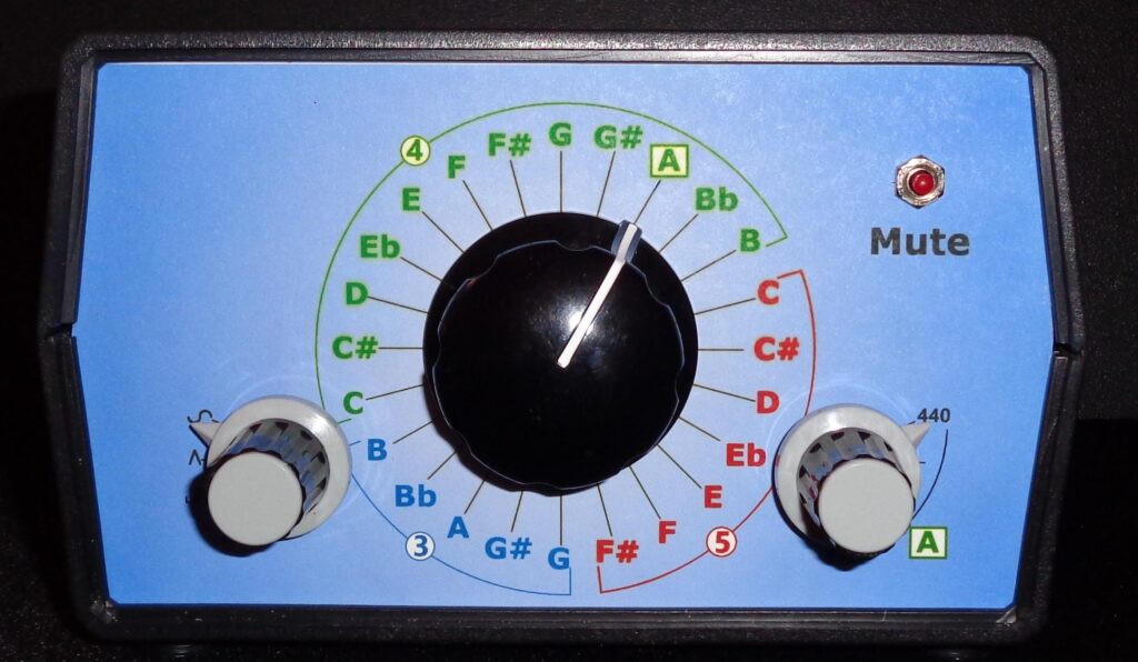
Electronic instrument tuners have existed now for several decades, but the ones with a great amount of precision can cost over a thousand dollars to the consumer, which is far above what many are willing or able to pay. To address this issue of high prices while still maintaining a high degree of accuracy Jan Herman built his own device that utilizes just a few relatively common parts.
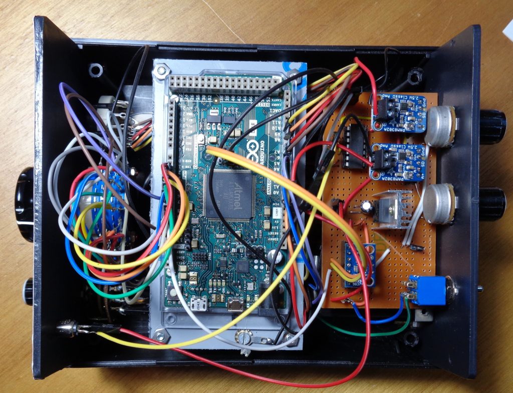
Within the housing of his tuner is an Arduino Due, which was selected because of its 32-bit architecture (for precision when measuring frequencies), faster speeds, and a large amount of GPIO pins. Apart from that, Herman included an AD9833 waveform generator breakout, a PAM8302 amplifier circuit, a pair of rotary potentiometers and switches for getting user inputs, and a transducer/speaker setup along with various passive components for power input.
Initially, Herman had planned to include a small speaker that would listen for feedback from the instrument and give the tuner an amount to adjust the string by. However, this proved to be too costly, thus why the transducer and speaker combination was chosen instead. When the user of this project wishes to adjust the frequency, they simply listen to the wave generator and attempt to match it.
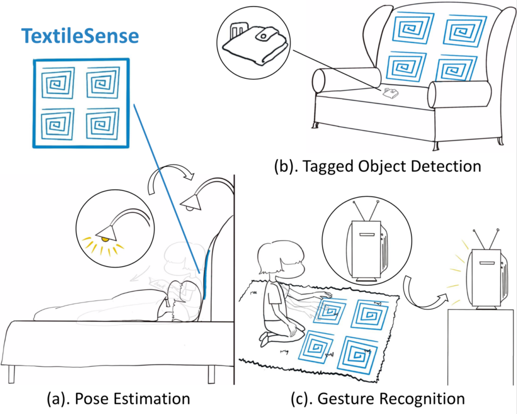
Near-field communication, or NFC for short, has started popping up everywhere as a way to easily pay, unlock doors, or even start a car. And now it can do one more thing: locate and track objects within a room. Researchers at Carnegie Mellon University’s Laboratory for Emerging Wireless Technologies have come up with an ingenious method to integrate NFC antennas into the fabric of pillows, furniture, and carpet to create smart environments.
Their system, which they call “TextileSense,” takes advantage of multiple-input and multiple-output (MIMO) antenna arrays to make aimed beams of radio waves that can be measured when they interact with a conductive object, like a hand.
The team plans on using this technology to perform various functions around the house such as allowing furniture to detect when a person is present, estimating the pose of someone who is sleeping, and letting carpet pick up gestures to control smart home devices. TextileSense can achieve accuracies of up to 3.6cm when using passive NFC tags and up to 2.9cm when detecting a human hand. All of this can be done at a max range of about 20.3cm using four software-defined radios, which helps address some of the privacy concerns associated with a system like this.
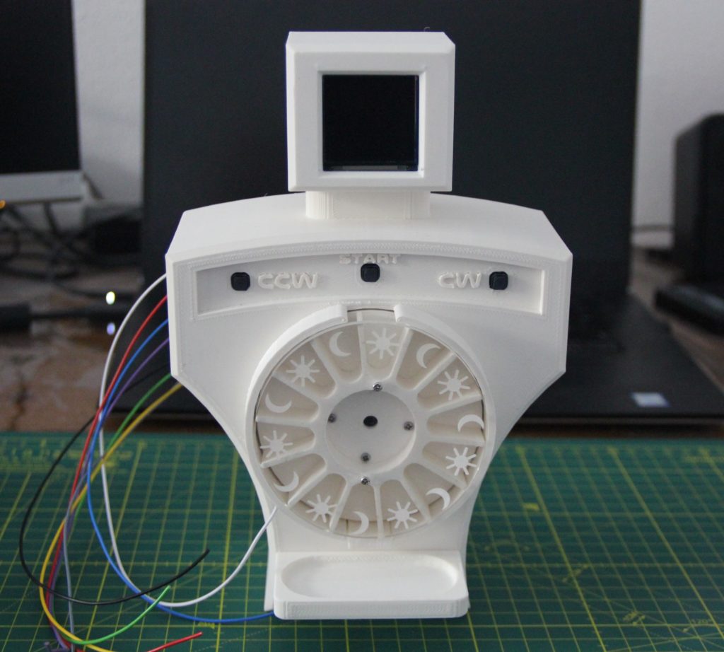
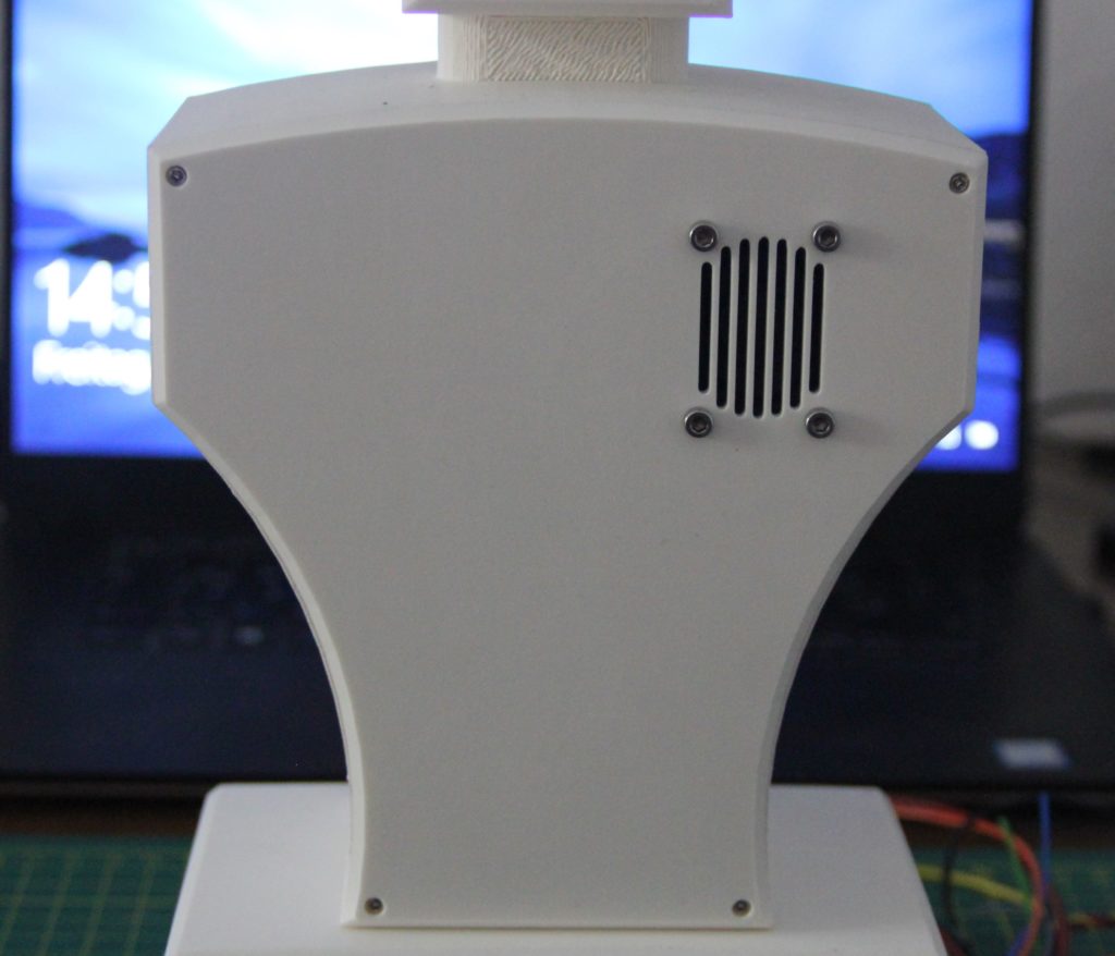
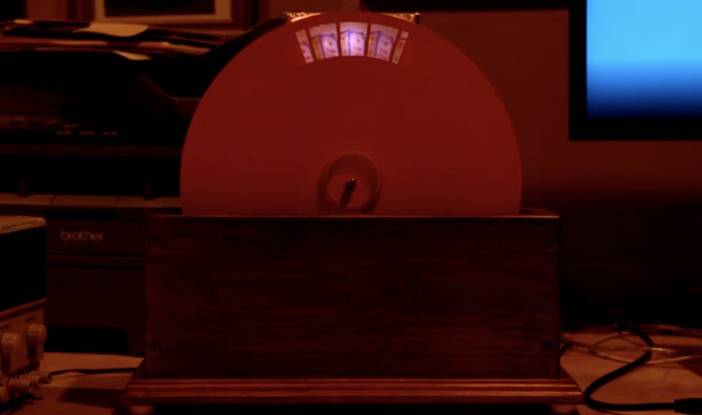
Nearly everyone alive today has never the technical marvel that is the mechanical television. In short, the work by quickly strobing a light through a disc that has holes cut around its perimeter, with each hole being slightly lower than its predecessor. Combined with the persistence of vision effect, this gives the illusion of a still image with its number of rows being equal to the number of holes in the disc. YouTuber “Science ‘n’ Stuff” wanted to try creating a modern version that uses a microcontroller to precisely adjust an LED’s color, rather than using an analog signal.
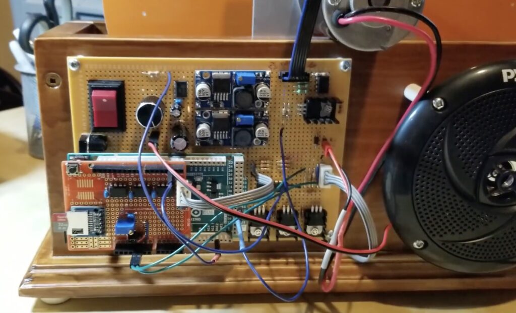
The device has a single large plastic disc with 32 holes for a total of 32 rows in the image. It’s spun at 1500 RPM by a DC motor that’s driven via PWM, and because there can be some variance in the motor’s speed, the synchronization signal that’s produced on each full rotation is also used to carefully adjust the motor’s speed to keep it constant. Both images and sound are read from an onboard microSD card, with the images being converted into pulses of light and the sound being played on a mono speaker. All of this is controlled by an Arduino Due board.
To learn more about how this project works, you can view its detailed explanation in the first video below and a simple demonstration of the TV in the second clip.
Planet Arduino is, or at the moment is wishing to become, an aggregation of public weblogs from around the world written by people who develop, play, think on Arduino platform and his son. The opinions expressed in those weblogs and hence this aggregation are those of the original authors. Entries on this page are owned by their authors. We do not edit, endorse or vouch for the contents of individual posts. For more information about Arduino please visit www.arduino.cc
You are currently browsing the archives for the DUE category.