When we need precision and repeatability, a stepper motor is always the solution. With the way it is designed, a stepper can only move from one step to the next and fix in that position. A typical motor has 200 steps per revolution; if we tell the motor to go 100 steps in one direction, it will turn exactly 180 degrees. It gets interesting when we only tell it to go one step and it turns exactly 1.8 degrees.
Skateboards are fun, but you have to do all that pesky kicking in order to get anywhere. That’s why [Nick] decided to build his own electric skateboard. Not only is the skateboard powered with an electric motor, but the whole thing can be controlled from a smart phone.
[Nick] started out with a long board deck that he had made years ago. After cleaning it up and re-finishing it, the board was ready for some wheels. [Nick] used a kit he found online that came with the trucks, wheels, and a belt. The trucks have a motor mount welded in place already. [Nick] used a Turnigy SK3 192KV electric motor to drive the wheels. He also used a Turnigy electronic speed controller to make sure he could vary the speed of the board while riding.
Next [Nick] needed some interface between a smart phone and the motor controller. He chose to use an Arduino Nano hooked up to a Bluetooth module. The Nano was able to directly drive the motor controller, and the Bluetooth module made it easy to sync up to a mobile phone. The Android app was written using MIT’s App Inventor software. It allows for basic control over the motor speed so you can cruise in style. Check out the video below for a slide show and some demonstration clips.
Stepper motors are brushless DC motors which can move in discrete steps thanks to the special coil arrangement inside. They are very popular in DIY and industry projects which require accurate mechanical movement control. In this SoloPCB project, we are building a dual stepper motor driver shield based on two Allegro A4988 ICs which can supply up to 35V and 2A and provide overcurrent and thermal protection.
DIY Dual Stepper Motor Driver Shield for Arduino – [Link]
arduino, BLDC, L6234, mosfet, motorComments Off on Spining BLDC motors at super Slow speeds with Arduino and L6234
by berryjam.eu:
I used specialized triple half bridge IC L6234 (~ 8$). You can make the same spending less money (but more time) with MOSFET transistors or other IC.
L6234 datasheet is surprisingly useless. Go straight to Application Note AN1088 instead.
I added current limiting resistors (1kΩ) to all INputs and ENable pins, a bunch of capacitors recommended in application note and current sensing shunt resistor 0.6Ω (big blue one).
Spining BLDC motors at super Slow speeds with Arduino and L6234 - [Link]
[Jordan] managed to cobble together his own version of a low resolution digital camera using just a few components. The image generated is pretty low resolution and is only in grey scale, but it’s pretty impressive what can be done with some basic hardware.
The heart of the camera is the image sensor. Most consumer digital cameras have tons of tiny receptors all jammed into the sensor. This allows for a larger resolution image, capturing more detail in a smaller space. Unfortunately this also usually means a higher price tag. [Jordan’s] sensor includes just a single pixel. The sensor is really just an infrared photodiode inside of a tube. The diode is connected to an analog input pin on an Arduino. The sensor can be pointed at an object, and the Arduino can sense the brightness of that one point.
In order to compile an actual image, [Jordan] needs to obtain readings of multiple points. Most cameras do this using the large array of pixels. Since [Jordan’s] camera only has a single pixel, he has to move it around and take each reading one at a time. To accomplish this, the Arduino is hooked up to two servo motors. This allows the sensor to be aimed horizontally and vertically. The Arduino slowly scans the sensor in a grid, taking readings along the way. A Processing application then takes each reading and compiles the final image.
Since this camera compiles an image so slowly, it sometimes has a problem with varying brightness. [Jordan] noticed this issue when clouds would pass over while he was taking an image. To fix this problem, he added an ambient light sensor. The Arduino can detect the amount of overall ambient light and then adjust each reading to compensate. He says it’s not perfect but the results are still an improvement. Maybe next time he can try it in color.
Infineon have announced two shields for the Arduino development environment. The RGB LED Lighting Shield (shown left) provides three independent output channels with a DC/DC LED driver stage to give flicker-free control of multicolor LEDs. It is fitted with an XMC1202 microcontroller using a Brightness Color Control Unit (BCCU) to help off-load time-critical events from the Arduino processor. The Shield can be expanded by adding an optional isolated DMX512 interface for stage lighting control and audio nodes or a 24 GHz radar sensor for motion detection.
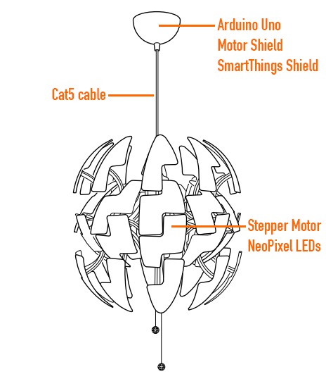
Ikea hacks are well widespread in the maker movement and David Bliss, founder at Nurun, did a great job transforming the Death Star inspired PS 2014 Pendant Lamp into something more dynamic.
The lamp was pimped up with an Arduino Uno and Arduino Motor Shield, NeoPixel LEDs and other components you can see in the illustration.
The detailed description of the project is on his blog , the code on github and the final result in the following video:
You don’t have to spend a lot of money to control motors with an Arduino or compatible board. After some hunting around we found a neat motor control module based on the L298N H-bridge IC that can allows you to control the speed and direction of two DC motors, or control one bipolar stepper motor with ease.
The L298N H-bridge module can be used with motors that have a voltage of between 5 and 35V DC. With the module used in this tutorial, there is also an onboard 5V regulator, so if your supply voltage is up to 12V you can also source 5V from the board.
So let’s get started!
First we’ll run through the connections, then explain how to control DC motors then a stepper motor. At this point, review the connections on the L298N H-bridge module.
Consider the following image – match the numbers against the list below the image:
DC motor 1 “+” or stepper motor A+
DC motor 1 “-” or stepper motor A-
12V jumper – remove this if using a supply voltage greater than 12V DC. This enables power to the onboard 5V regulator
Connect your motor supply voltage here, maximum of 35V DC. Remove 12V jumper if >12V DC
GND
5V output if 12V jumper in place, ideal for powering your Arduino (etc)
DC motor 1 enable jumper. Leave this in place when using a stepper motor. Connect to PWM output for DC motor speed control.
IN1
IN2
IN3
IN4
DC motor 2 enable jumper. Leave this in place when using a stepper motor. Connect to PWM output for DC motor speed control.
DC motor 2 “+” or stepper motor B+
DC motor 2 “-” or stepper motor B-
Controlling DC Motors
To control one or two DC motors is quite easy with the L298N H-bridge module. First connect each motor to the A and B connections on the L298N module. If you’re using two motors for a robot (etc) ensure that the polarity of the motors is the same on both inputs. Otherwise you may need to swap them over when you set both motors to forward and one goes backwards!
Next, connect your power supply – the positive to pin 4 on the module and negative/GND to pin 5. If you supply is up to 12V you can leave in the 12V jumper (point 3 in the image above) and 5V will be available from pin 6 on the module. This can be fed to your Arduino’s 5V pin to power it from the motors’ power supply. Don’t forget to connect Arduino GND to pin 5 on the module as well to complete the circuit.
Now you will need six digital output pins on your Arduino, two of which need to be PWM (pulse-width modulation) pins. PWM pins are denoted by the tilde (“~”) next to the pin number, for example:
Finally, connect the Arduino digital output pins to the driver module. In our example we have two DC motors, so digital pins D9, D8, D7 and D6 will be connected to pins IN1, IN2, IN3 and IN4 respectively. Then connect D10 to module pin 7 (remove the jumper first) and D5 to module pin 12 (again, remove the jumper).
The motor direction is controlled by sending a HIGH or LOW signal to the drive for each motor (or channel). For example for motor one, a HIGH to IN1 and a LOW to IN2 will cause it to turn in one direction, and a LOW and HIGH will cause it to turn in the other direction.
However the motors will not turn until a HIGH is set to the enable pin (7 for motor one, 12 for motor two). And they can be turned off with a LOW to the same pin(s). However if you need to control the speed of the motors, the PWM signal from the digital pin connected to the enable pin can take care of it.
This is what we’ve done with the DC motor demonstration sketch. Two DC motors and an Arduino Uno are connected as described above, along with an external power supply. Then enter and upload the following sketch:
// connect motor controller pins to Arduino digital pins
// motor one
int enA = 10;
int in1 = 9;
int in2 = 8;
// motor two
int enB = 5;
int in3 = 7;
int in4 = 6;
void setup()
{
  // set all the motor control pins to outputs
  pinMode(enA, OUTPUT);
  pinMode(enB, OUTPUT);
  pinMode(in1, OUTPUT);
  pinMode(in2, OUTPUT);
  pinMode(in3, OUTPUT);
  pinMode(in4, OUTPUT);
}
void demoOne()
{
  // this function will run the motors in both directions at a fixed speed
  // turn on motor A
  digitalWrite(in1, HIGH);
  digitalWrite(in2, LOW);
  // set speed to 200 out of possible range 0~255
  analogWrite(enA, 200);
  // turn on motor B
  digitalWrite(in3, HIGH);
  digitalWrite(in4, LOW);
  // set speed to 200 out of possible range 0~255
  analogWrite(enB, 200);
  delay(2000);
  // now change motor directions
  digitalWrite(in1, LOW);
  digitalWrite(in2, HIGH);
  digitalWrite(in3, LOW);
  digitalWrite(in4, HIGH);
  delay(2000);
  // now turn off motors
  digitalWrite(in1, LOW);
  digitalWrite(in2, LOW);
  digitalWrite(in3, LOW);
  digitalWrite(in4, LOW);
}
void demoTwo()
{
  // this function will run the motors across the range of possible speeds
  // note that maximum speed is determined by the motor itself and the operating voltage
  // the PWM values sent by analogWrite() are fractions of the maximum speed possible
  // by your hardware
  // turn on motors
  digitalWrite(in1, LOW);
  digitalWrite(in2, HIGH);
  digitalWrite(in3, LOW);
  digitalWrite(in4, HIGH);
  // accelerate from zero to maximum speed
  for (int i = 0; i < 256; i++)
  {
    analogWrite(enA, i);
    analogWrite(enB, i);
    delay(20);
  }
  // decelerate from maximum speed to zero
  for (int i = 255; i >= 0; --i)
  {
    analogWrite(enA, i);
    analogWrite(enB, i);
    delay(20);
  }
  // now turn off motors
  digitalWrite(in1, LOW);
  digitalWrite(in2, LOW);
  digitalWrite(in3, LOW);
  digitalWrite(in4, LOW);
}
void loop()
{
  demoOne();
  delay(1000);
  demoTwo();
  delay(1000);
}
So what’s happening in that sketch? In the function demoOne() we turn the motors on and run them at a PWM value of 200. This is not a speed value, instead power is applied for 200/255 of an amount of time at once.
Then after a moment the motors operate in the reverse direction (see how we changed the HIGHs and LOWs in thedigitalWrite() functions?).
To get an idea of the range of speed possible of your hardware, we run through the entire PWM range in the function demoTwo() which turns the motors on and them runs through PWM values zero to 255 and back to zero with the two for loops.
Finally this is demonstrated in the following video – using our well-worn tank chassis with two DC motors:
Controlling a Stepper Motor
Stepper motors may appear to be complex, but nothing could be further than the truth. In this example we control a typical NEMA-17 stepper motor that has four wires:
It has 200 steps per revolution, and can operate at at 60 RPM. If you don’t already have the step and speed value for your motor, find out now and you will need it for the sketch.
The key to successful stepper motor control is identifying the wires – that is which one is which. You will need to determine the A+, A-, B+ and B- wires. With our example motor these are red, green, yellow and blue. Now let’s get the wiring done.
Connect the A+, A-, B+ and B- wires from the stepper motor to the module connections 1, 2, 13 and 14 respectively. Place the jumpers included with the L298N module over the pairs at module points 7 and 12. Then connect the power supply as required to points 4 (positive) and 5 (negative/GND).
Once again if your stepper motor’s power supply is less than 12V, fit the jumper to the module at point 3 which gives you a neat 5V power supply for your Arduino.
Next, connect L298N module pins IN1, IN2, IN3 and IN4 to Arduino digital pins D8, D9, D10 and D11 respectively. Finally, connect Arduino GND to point 5 on the module, and Arduino 5V to point 6 if sourcing 5V from the module.
Controlling the stepper motor from your sketches is very simple, thanks to the Stepper Arduino library included with the Arduino IDE as standard.
To demonstrate your motor, simply load the stepper_oneRevolution sketch that is included with the Stepper library, for example:
Finally, check the value for
const int stepsPerRevolution = 200;
in the sketch and change the 200 to the number of steps per revolution for your stepper motor, and also the speed which is preset to 60 RPM in the following line:
myStepper.setSpeed(60);
Now you can save and upload the sketch, which will send your stepper motor around one revolution, then back again. This is achieved with the function
	myStepper.step(stepsPerRevolution); // for clockwise
	myStepper.step(-stepsPerRevolution); // for anti-clockwise
Finally, a quick demonstration of our test hardware is shown in the following video:
So there you have it, an easy an inexpensive way to control motors with your Arduino or compatible board. And if you enjoyed this article, or want to introduce someone else to the interesting world of Arduino – check out my book (now in a fourth printing!) “Arduino Workshop”.
Have fun and keep checking into tronixstuff.com. Why not follow things on twitter, Google+, subscribe for email updates or RSS using the links on the right-hand column, or join our forum – dedicated to the projects and related items on this website.
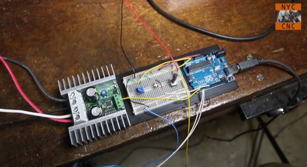
Arduino boards are able to control small motors very easily and it’s just as easy when you have to deal with controlling large motors. In the following video tutorial by NYC CNC you’ll see two examples. In the first you’ll learn how to get up and running, to start, stop, control direction and speed of a large motor with Arduino Uno. In the second example, how to use two proximity sensors as limit switches and two potentiometers to allow on-the-fly speed adjustment.
Planet Arduino is, or at the moment is wishing to become, an aggregation of public weblogs from around the world written by people who develop, play, think on Arduino platform and his son. The opinions expressed in those weblogs and hence this aggregation are those of the original authors. Entries on this page are owned by their authors. We do not edit, endorse or vouch for the contents of individual posts. For more information about Arduino please visit www.arduino.cc
You are currently browsing the archives for the motor category.

 Artist David Cranmer's "Stakcgrox" is a 3.5 meter tall robotic crow with a rotating head and glowing eyes that shoot lasers.