Posts | Comments

Planet Arduino

Archive for the ‘arduino hacks’ Category

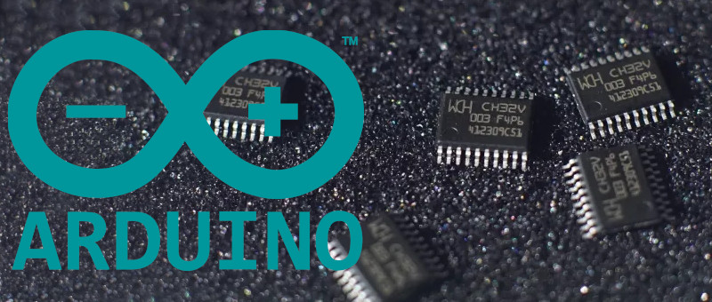
Like many of you, we’ve been keeping a close eye on the CH32 family of RISC-V microcontrollers from WCH Electronics. You can get the CH32V003, featuring 2 kB RAM and 16 kB of flash for under fifteen cents, and the higher-end models include impressive features like onboard Ethernet. But while the hardware is definitely interesting, the software side of things has been a little rocky compared to what we’ve come to expect from modern MCUs.

Things should start looking up a bit though with the release of an Arduino core for the CH32 direct from WCH themselves. It’s been tested on Windows, Linux, and Mac, and supports the CH32V00x, CH32V10x, CH32V20x, CH32V30x, and CH32X035 chips. Getting it installed is as easy as adding the URL to the Arduino IDE’s Boards Manager interface, though as the video below shows, running it on Linux does require an extra step or two.

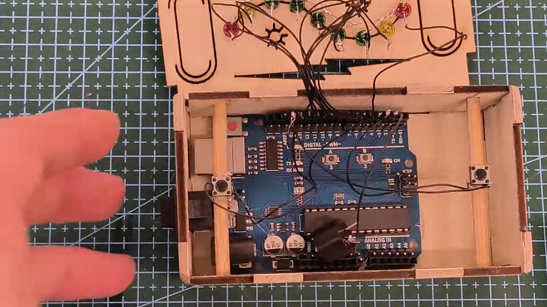
So far, we’ve seen several projects, like this temperature sensor or this holiday gizmo that use [cnlohr]’s open-source toolchain. But there’s no question that plenty of hobbyists out there feel more comfortable in the Arduino environment, and if those folks are now able to pick up a CH32 and do something cool, that means more people jumping on board, more libraries developed, more demo code written…you get the idea.

Just like the ESP8266’s popularity exploded when it was added to the Arduino IDE, we’ve got high hopes for the CH32 family in the coming months.

There are many ways to lock a door. You could use a keypad, an RFID card, a fingerprint or retina scan, Wi-Fi, Bluetooth, the list goes on. You could even use a regular old metal key. But none of these may be as secure as [mircemk]’s Arduino-based door lock that employs a smartphone’s flashlight as a pass code.

At first blush, this seems horribly insecure. Use a plain old flashlight to open a door? Come on. But the key is in the software. In fact, between the typed-in pass code and the flash of light it generates, this lock kind of has two layers of security.

Here’s what’s going on: inside the accompanying smart phone application, there’s a list of passwords. Each of these passwords corresponds to a flash of light in milliseconds. Enter the correct password to satisfy the Arduino, and the phone’s flashlight is activated for the appropriate number of milliseconds to unlock the door.

As you’ll see in the video below, simply flashing the light manually doesn’t unlock the door, and neither does entering one of the other, bogus passwords. Although it does activate the flashlight each time, they don’t have the appropriate light-time length defined.

Hardware-wise, there is an Arduino Nano Every in charge of the LDR module that reads the flashlight input and the 12 V relay that unlocks the door. Be sure to check it out it the video after the break.

If you want to keep your critters from bringing wild critters back inside, check out this Wi-Fi cat door that lets you have a look at what might be dangling from their jaws before unlocking the door.

The equipment used in professional radio and TV studios is both extremely high quality and very expensive indeed, and thus out of the reach of an experimenter. Happily as studios are refurbished there’s a steady supply of second-hand equipment which can be surprisingly cheap, but as [Nathan] found out with a Quartz audio router, comes with no control software. What’s to be done with what’s essentially a piece of junk? Remove its brain and replace it with one that can be controlled, of course!

On the PCB alongside a bank of switch matrices is an FPGA which does the heavy lifting. That’s “heavy” in a limited sense, because all it does is handle the chip select lines for the matrices and write data to their registers. This is a task that can be handled by a microcontroller, so in goes an Arduino Nano, which along with a few other board modifications delivers a serial-controlled studio router.

The interesting part for us in this project comes from a look at the date codes on the board, they’re from the early 2000s. This is (roughly) contemporary with the ATmega chip on the Arduino, so we’re curious as to why the designers saw fit to use an FPGA when the microcontrollers of the day were clearly up to the task for much less outlay. We suspect a touch of millennium-era price inflation, but we can’t be sure.

Meanwhile, old broadcast kit has featured here before.

Thermal cameras can cost well into the five-figure range if you’re buying high-resolution models with good feature sets. New models can be so advanced that their export and use is heavily controlled by certain countries, including the USA. If you just want to tinker at the low end, though, you don’t have to spend a lot of scratch. You can even build yourself something simple based on an Arduino Uno!

The build uses Panasonic’s cheap “Grid-EYE” infrared array as the thermal sensor, in this case, a model with an 8×8 array of thermopiles. It’s not going to get you any fancy images, especially at long range, but you can use it to get a very blocky kind of Predator-vision of the thermal radiation environment. It’s a simple matter of hooking up the Grid-EYE sensor to the Arduino Uno over I2C, and then spitting out the sensor’s data in a nice visual form on a cheap TFT screen.

It’s a great introduction to the world of thermal imaging. There’s no better way to learn how something works by building a working example yourself. We’ve featured a few similar projects before, too; it’s all thanks to the fact that thermal sensors are getting cheaper and more accessible than ever!

VFD displays are beloved for their eerie glow that sits somewhere just off what you’d call blue. [mircemk] used one of these displays to create an old-school VU meter that looks straight out of a 1970s laboratory. 

The build uses an Arduino Nano as the brains of the operation, which uses its analog inputs to process incoming audio into decibel levels for display on a VU meter. It’s then charged with driving a GP1287 VFD display. Unlike some VFDs that have preset segments that can be illuminated or switched off, this is a fully graphical dot matrix display that can be driven as desired. Thus, when it’s not acting as a bar graph VU meter, it can also emulate old-school moving-needle meters. Though, it bears noting, the slow updates the Arduino makes to the display means it’s kind of like those dodgy skeumorphic music apps of the 16-bit era; i.e. it’s quite visually jerky.

Overall, it’s a neat project that demonstrates how to work with audio, microcontrollers, and displays all in one. We’ve featured other projects from [mircemk] before, too, almost all of which appear in the same blue and grey project boxes. Video after the break.

[Trent M. Wyatt]’s CPUVolt library provides a fast way to measure voltage using no external components, and no I/O pin. It only applies to certain microcontrollers, but he provides example Arduino code showing how handy this can be for battery-powered projects.

The usual way to measure VCC is simple, but has shortcomings.

The classical way to measure a system’s voltage is to connect one of your MCU’s ADC pins to a voltage divider made from a couple resistors. A simple calculation yields a reading of the system’s voltage, but this approach has two disadvantages: one is that it constantly consumes power, and the other is that it ties up a pin that you might want to use for something else.

There are ways to mitigate these issues, but it would be best to avoid them entirely. Microchip application note 2447 describes a method of doing exactly that, and that’s precisely what [Trent]’s Arduino library implements.

What happens in this method is one selects Vbg (a fixed internal voltage reference that is temperature-independent) as Vin, and selects Vcc as the ADC’s voltage reference. This is essentially backwards from how the ADC is normally used, but it requires no external hookup and is only a bit of calculation away from determining Vcc in millivolts. There is some non-linearity in the results, but for the purposes of measuring battery power in a system or deciding when to send a “low battery” signal, it’s an attractive solution.

Being an Arduino library, CPUVolt makes this idea very easy to use, but the concept and method is actually something we have seen before. If you’re interested in the low-level details, then check out our earlier coverage which goes into some detail on exactly what is going on, using an ATtiny84.

In Disney’s 1991 film Beauty and the Beast, an enchantress curses the young (10 or 11-year-old) prince to beast-hood for spurning her based solely on her appearance. She gives him a special rose that she says will bloom until his 21st birthday, at which time he’ll be turned back into a prince, provided that he learned to love by then. If not, he’ll be a beast for eternity. As the years go by, the rose drops the occasional petal and begins to wilt under the bell jar where he keeps it.

[Gord Payne] was tasked with building such a rose of enchantment for a high school production and knocked it out of the park. With no budget provided, [Gord] used what he had lying about the house, like nylon trimmer line. In fact, that’s probably the most important part of this build. A piece of trimmer line runs up through the stem made of tubing and out the silk rose head, which connects with a custom 3-D printed part.

Each loose petal hangs from the tubing using a short length of wire. Down at the base, the trimmer line is attached to a servo horn, which is connected to an Adafruit Circuit Playground. When the button is pressed on the remote, the servo retracts the trimmer line a little bit, dropping a petal. Be sure to check out the demo after the break.

Dropping petals is an interesting problem to solve. Most of the flower hacks we see around here involve blooming, which presents its own set of troubles.

Maybe it’s just us, but isn’t it kind of amazing that in a world of pretty darn realistic games, PONG is still thrilling to play? This 1D implementation by [newsonator] is about as exciting as it gets.

It works like you’d probably expect — the light moves back and forth between the two players. Keep it in the green and you have a nice, gentle volley going. Let it hit your red LED and you’ve lost a point. But if you can push your button while your yellow LED is lit, the light speeds up tremendously until the next button press in the green.

Our only wish is that subsequent yellow-light button presses would make it speed up even more. But there are really just the two speeds with the current programming.

Inside the cool laser-cut box is an Arduino Uno and a 9V battery, plus a current-limiting resistor and the all-important buzzer. We like how [newsonator] wired up the LEDs to the Arduino by soldering them to a row of header pins and sticking that into the Arduino so it can be used in other projects down the line. We also like how [newsonator] shoved a couple of dowels through the box to ultimately support the two buttons.

Check out the intro video after the break for the overall details. The build is done over a few different short videos which follow.

Although this is pretty small, it isn’t quite the minimum viable.


It is one thing to make an artistic steampunk display. But [CapeGeek] added an Arduino to make the display come alive. The display has plenty of tubes and wires. The pressure gauge dominates the display, but there are lots of other interesting bits. Check it out in the video below.

From the creator:

The back-story is a fictional factory that cycles through a multistage process. It starts up with lights and sounds starting in a small tube in one corner, the needle on a big gauge starts rising, then a larger tube at the top lights up in different colors. Finally, the tall, glass reactor vessel lights up to start cooking some process. All this time, as the sequence progresses, it is accompanied by factory motor sounds and bubbling processes. Finally, a loud glass break noise hints that the process has come to a catastrophic end! Then the sequence starts reversing, with lights sequentially shutting down, the needle jumps around randomly, then decreases, finally, all lights are off, indicating the factory shutting down.

We especially liked the distillation column. We doubt we would exactly duplicate this project, but there are plenty of things to borrow for your own creations here.

We always enjoy steampunk computers. But we also like the ones that have unusual components like the distillation column or a chain.

[Lex] over at Computing: The Details loves to make fun projects. Recently, he’s created a hardware CPU monitor that allows him to see how well his PC is parallelizing compile tasks at a glance. The monitor is built from 14 analog meters, along with some WS2812 RGB LEDs.

Each meter represents a core on [Lex]’s CPU, while the final two meters show memory and swap usage. The meters themselves are low-cost 5 mA devices. Of course, the original milliamps legends wouldn’t do much good, so [Lex] designed and printed graduations that glue over the top. The RGB LED strip is positioned so two LEDs fit under each meter. The LEDs allow a splash of color to draw attention to the current state of the machine. The whole bank going red would sure get our attention!

The system is controlled by an Arduino Mega, with the meters driven using the PWM pins. The only extra part is a 1 K resistor. The Arduino wrangles the LEDs as well. Sadly [Lex] did not include his software. He did describe it though. Basically he’s using a Rust program to call systemstat, obtaining the current CPU utilization data in Linux. A bit of math converts this into pointer values and LED colors. The data is then sent via USB-serial to the Arduino Mega. The software savvy will say it’s pretty easy to replicate, but the hardware only hackers among us might need a bit of help.

This isn’t the first custom meter we’ve seen on Hackaday. Your author’s first project covered by Hackaday was for a meter created using an automotive gauge stepper motor. I didn’t include source code either – but only because [Guy Carpenter]’s Switec X25 library had me covered.

Thanks for the tip, [TubeTime]!


  • Newsletter

    Sign up for the PlanetArduino Newsletter, which delivers the most popular articles via e-mail to your inbox every week. Just fill in the information below and submit.

  • Like Us on Facebook