Posts | Comments

Planet Arduino

Archive for the ‘gsm’ Category

Dec
11

Over-engineering Ding Dong Ditch

arduino, arduino hacks, ask, doorbell, gsm, OOK, radio, radio hacks, RTL-SDR Comments Off on Over-engineering Ding Dong Ditch 

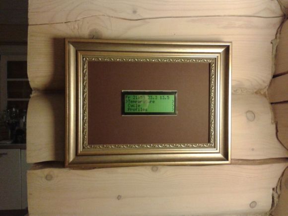
One day, [Samy]’s best friend [Matt] mentioned he had a wireless doorbell. Astonishing. Even more amazing is the fact that anyone can buy a software defined radio for $20, a small radio module from eBay for $4, and a GSM breakout board for $40. Connect these pieces together, and you have a device that can ring [Matt]’s doorbell from anywhere on the planet. Yes, it’s the ultimate over-engineered ding dong ditch, and a great example of how far you can take practical jokes if you know which end of a soldering iron to pick up.

Simply knowing [Matt] has a wireless doorbell is not enough; [Samy] needed to know the frequency, the modulation scheme, and what the doorbell was sending. Some of this information can be found by looking up the FCC ID, but [Samy] found a better way. When [Matt] was out of his house, [Samy] simply rang the doorbell a bunch of times while looking at the waterfall plot with an RTL-SDR TV tuner. There are a few common frequencies tiny, cheap remote controls will commonly use – 315 MHz, 433 MHz, and 900 MHz. Eventually, [Samy] found the frequency the doorbell was transmitting at – 433.8 MHz.

After capturing the radio signal from the doorbell, [Samy] looked at the audio waveform in Audacity. It looked like this doorbell used On-Off Keying, or just turning the radio on for a binary ‘1’ and off for a binary ‘0’. In Audacity, everything the doorbell transmits becomes crystal clear, and with a $4 434 MHz transmitter from SparkFun, [Samy] can replicate the output of the doorbell.

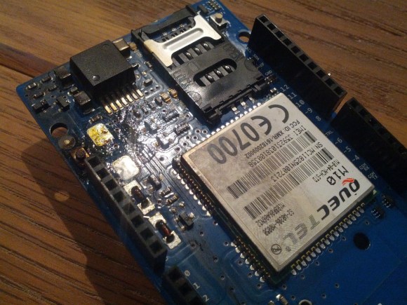
For the rest of the build, [Samy] is using a mini GSM cellular breakout board from Adafruit. This module listens for any text message containing the word ‘doorbell’ and sends a signal to an Arduino. The Arduino then sends out the doorbell code with the transmitter. It’s evil, and extraordinarily over-engineered.

Right now, the ding dong ditch project is set up somewhere across the street from [Matt]’s house. The device reportedly works great, and hopefully hasn’t been abused too much. Video below.


Filed under: Arduino Hacks, radio hacks
Oct
17

The Arduino compatible MicroLink

arduino, ATmega328, gsm, kickstarter, MicroLink, SIM800H, USB Comments Off on The Arduino compatible MicroLink 

ArduinoMicroLink

by elektor.com:

If Arduino is your development platform of choice the tiny self-contained MicroLink board offers some interesting features. At just 50 x 32 mm it contains an ATmega328, an SIM800H quad band GSM module and on-board USB and battery charging capabilities. It has all the peripherals necessary to allow wireless remote control and monitoring and can use any standard 3.7 V LiPo battery for power which is charged when the USB port is connected. The charge state can be checked at any time from a remote location.

The Arduino compatible MicroLink - [Link]

Sep
26

Arduino hacked ericsson mobile phone GSM remote control

arduino, Ericsson T65, gsm, remote control, sms Comments Off on Arduino hacked ericsson mobile phone GSM remote control 

Arduino hacked Ericsson T65 mobile phone GSM remote control. By Konstantinos Kokoras @ youtube.com:

Accepting incoming call from predifined caller and after 2 rings hungs up and turns on a device through a relay.
Also accepting incoming SMS’s from predifined caller and depending from text tuns on or off a device through a relay.
After each command execution it sends back a confirmation SMS.
Unfortunately Ericsson T65 has only PDU mode for SMS.

Arduino hacked ericsson mobile phone GSM remote control - [Link]

Aug
01

Arduino GSM home automation system

arduino, automation, DS18B20, gsm, sim900 Comments Off on Arduino GSM home automation system 

FAH04K9HY3ZC1CN-600x600

Timofte Andrei wrote this instructable detailing the build of his Arduino home automation system:

For this project I’ve used:
1. An Arduino clone
2. SIM900 GSM SHIELD
3. Relay module
4. 2×16 LCD Display
5. DS18B20 temperature sensor
6. Push button
7. Some Dupont wires
8. A led module (this is optional, if you have a chinese relay module with built in LEDs)
9. Some nuts and bolts to mount everything in place
10. A wooden chopping board or other kind of wooden board for propper display of the components

[via]

Arduino GSM home automation system - [Link]

Jun
19

Arduino GPS GSM AnyTracer

AnyTracer, arduino, gps, gsm, STM32 Comments Off on Arduino GPS GSM AnyTracer 

20140518091311-AnyTracerGPS

Track and Trace anything with the Arduino AnyTracer of only 25 x 25 mm! It is the smallest, complete GPS GSM tracker in the entire world.

A movie is not necessary here! The photos speak for itself. Together with the best Italian and Russian GPS specialists we managed to make the smallest complete GPS GSM tracker in the world. This tracker is only 25 x 25 mm! With the onboard STM32 microcontroller you can program it yourself with Arduino or online (!) with Mbed.org or in C using Keil or the opensource CooCox IDE. Almost anybody can do the programming with their own beloved platform.

Arduino GPS GSM AnyTracer - [Link]

Feb
06

New Project: The Connected Office: Text Message-Based Remote Display

3D printing, arduino, Computers & Mobile, gsm, in out board, makerbot, sms, text message Comments Off on New Project: The Connected Office: Text Message-Based Remote Display 

bebackAt work, I often use a Post-it note stating my whereabouts on my office door for those who stop by looking for me when I am out. Some notes are one-time use like “On vacation. Back on 11/20.”, and some can be reused like “Up in the 3113 lab.” Sometimes, […]

Read more on MAKE

Introduction

Working with GSM modules and by extension Arduino GSM shields can either be a lot of fun or bring on a migraine. This is usually due to the quality of module, conditions placed on the end user by the network, reception, power supply and more.

Furthermore we have learned after several years that even after following our detailed and tested tutorials, people are having trouble understanding why their GSM shield isn’t behaving. With this in mind we’re very happy to have learned about a free online tool that can be used to test almost every parameter of a GSM module with ease – AT Command Tester. This software is a Java application that runs in a web browser, and communicates with a GSM module via an available serial port.

Initial Setup

It’s simple, just visit http://m2msupport.net/m2msupport/module-tester/ with any web browser that can run Java. You may need to alter the Java security settings down to medium. Windows users can find this in Control Panel> All Control Panel Items  > Java – for example:

Java security settings

Once the security settings have been changed, just visit the URL, click ‘accept’ and ‘run’ in the next dialogue box that will appear, for example:

run Java app

And after a moment, the software will appear:

at command tester

Once you’re able to run the AT Command Tester software, the next step is to physically connect the hardware. If you’re just using a bare GSM module, a USB-serial adaptor can be used for easy connection to the PC. For Arduino GSM shield users, you can use the Arduino as a bridge between the shield and PC, however if your GSM shield uses pins other than D0/D1 for serial data transmission (such as our SIM900 shield) then you’ll need to upload a small sketch to bridge the software and hardware serial ports, for example:

//Serial Relay – Arduino will patch a serial link between the computer and the GPRS Shield
//at 19200 bps 8-N-1 Computer is connected to Hardware UART
//GPRS Shield is connected to the Software UART

#include <SoftwareSerial.h>

SoftwareSerial mySerial(7,8); // change these paramters depending on your Arduino GSM Shield

void setup()
{
  Serial.begin(19200);
  //Serial.println(“Begin”);
  mySerial.begin(19200);

}

void loop()
{
  if (mySerial.available())
    Serial.write(mySerial.read());
  if (Serial.available())
    mySerial.write(Serial.read());
}

Using the software

Once you have the hardware connected and the Arduino running the required sketch, run the software – then click “Find ports” to select the requried COM: port, set the correct data speed and click “Connect”. After a moment the software will interrogate the GSM module and report its findings in the yellow log area:

at command tester connected

 As you can see on the left of the image above, there is a plethora of options and functions you can run on the module. By selecting the manufacturer of your GSM module form the list, a more appropriate set of functions for your module is displayed.

When you click a function, the AT command sent to the module and its response is shown in the log window – and thus the magic of this software. You can simply throw any command at the module and await the response, much easier than looking up the commands and fighting with terminal software. You can also send AT commands in batches, experiment with GPRS data, FTP, and the GPS if your module has one.

To give you a quick overview of what is possible, we’ve made this video which captures us running a few commands on a SIM900-based Arduino shield. If possible, view it in 720p.

Conclusion

Kudos to the people from the M2Msupport website for bringing us this great (and free) tool. It works – so we’re happy to recommend it. And if you enjoyed this article, or want to introduce someone else to the interesting world of Arduino – check out my book (now in a third printing!) “Arduino Workshop”.

visit tronixlabs.com

Have fun and keep checking into tronixstuff.com. Why not follow things on twitterGoogle+, subscribe  for email updates or RSS using the links on the right-hand column, or join our forum – dedicated to the projects and related items on this website. Sign up – it’s free, helpful to each other –  and we can all learn something.
Nov
08
wp15_step8_reshotbThis project uses the Seeed Studio GPRS/GSM v2.0 Shield to build a versatile Arduino-based remote alarm system that can notify your cell phone within seconds, via text message, when nearby doors or windows are opened or closed, pressure sensors depressed, or motion sensors activated, just to name a few of the many possibilities. Here we'll teach you how to connect simple motion, touch, pressure, and light sensors, and how to program the Arduino to use the shield to send text messages when these detect events. It's easy to adapt this system to use other sensor devices like temperature probes, magnetic switches, tilt sensors, etc.

Read more on MAKE

smsTempController

As connected as we are, reliable and affordable internet is still a luxury in the far reaches. [kohleick's] country home is not just remote; with temperatures dropping to -30C in the winter, it’s practically Arctic. His solution for controlling the thermostat from afar was to take advantage of the GSM network and implement a SMS-based heater controller. The unit typically operates in “antifreeze mode,” but sending a simple text message prior to visiting causes the heater to kick it up to a more comfortable setting for your arrival. Daily logs report the system’s status, and an alert will trigger when temperatures fall below a set limit, thus indicating potential faults with the heater.

The build uses a Freeduino paired with an external GSM modem for communication and an LCD to display current status and menus, which users access via three buttons on the side of the picture frame. [kohleick] connected two temperature sensors: one directly to the Freeduino’s shield and a second outside the house. After the temperature sensors detect deviance from the set point, or upon SMS instruction, the Freeduino will crank up the heat through a 5V relay attached to the home’s boiler. Head over to the Instructables page linked above for a bill of materials, schematics, and the code. The Siemens GSM modem in this build is nothing to worry about, but be careful if you try to reproduce this project with an Arduino GSM shield, or your house might really heat up.


Filed under: Arduino Hacks, Cellphone Hacks, home hacks, Microcontrollers

arduGSMfire

Be careful with those Arduino GSM cards. As [James] reports, they may turn into fire starters. One person has reported a small explosion and fire already on the Arduino forums.
Now before we go any further – You may be asking yourself who the heck [James] is, and what gives him the ability to second guess the Arduino team. Well, here is [James'] blog disclaimer:  “James is a Senior Technical Expert for Technology and Applications at KEMET Electronics, a capacitor manufacturer. The content of this post are his and in no way reflects opinions of his employer.”

Senior Technical Expert?  That’s a good enough reason for us to believe him.

[James] states the problem is a tantalum capacitor used to decouple the GSM radio power supply from the main Arduino supply.
Tantalum capacitors are great for their low ESR properties. However, they have a well known downside of getting very hot, or even exploding when stressed. It’s not the Tantalum Anode that is burning. The Manganese Dioxide used as a cathode in some Tantalum capacitors is the culprit.

It comes down to voltage rating (or more aptly, derating). The Arduino GSM shield runs at 5 volts. The designers chose a 6.3V rated capacitor. While this close of a tolerance may be good enough for some types of capacitor, it is a no-go for a Tantalum cap with Manganese Dioxide. The dielectric material in these capacitors is so thin that the stress of a reflow oven cycle causes cracks. The cracks pass leakage current, and this sets the Manganese Dioxide on the path to destruction.
What’s the solution? [James] suggests several options:

  1. Switch to a 10 volt part
  2. Switch to a safer Tantalum Polymer capacitor.

We haven’t heard anything from the Arduino team yet about this, but to be safe we’d follow [James'] advice.


Filed under: Arduino Hacks, news


  • Newsletter

    Sign up for the PlanetArduino Newsletter, which delivers the most popular articles via e-mail to your inbox every week. Just fill in the information below and submit.

  • Like Us on Facebook