Posts | Comments

Planet Arduino

Archive for the ‘android hacks’ Category

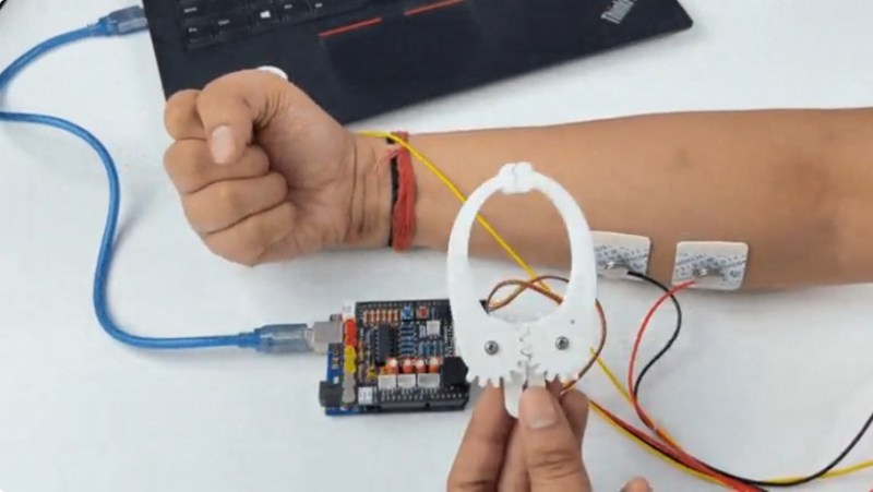
As fun as claw games are, the jaws are always disappointingly weak, and you usually end up with bupkis. What if the jaws were completely within your  control? That’s the idea behind [Upside Down Labs]’ muscle-controlled servo claw game.

While electromyography (EMG) is great for identifying neuro-muscular abnormalities and allows for amazing prosthetic limbs to work, it can also be used for fun. As you’ll see in the video after the break, accurate block-stacking (and possible candy-grabbing) depends on teamwork and tensed muscles.

Though the user provides the muscle, the brains behind this operation is an Arduino Uno with a Muscle BioAmp shield stacked on top, which [Upside Down Labs] also created. This shield makes it ridiculously easy to connect EMG sensors and other I²C devices like screens and, well, servo claws. From there, it’s really just a matter of printing the claw, connecting it to a 9g servo, and using an accompanying kit to prepare the skin and connect the muscles to the Arduino. Be sure to check it out in tense block-stacking action after the break.

If you want to listen in on your muscles, look no further than the BioAmp EMG Pill.

It used to be that upgrading a car stereo was fairly simple. There were only a few mechanical sizes and you could find kits to connect power, antennas, and speakers. Now, though, the car stereo has interfaces to steering wheel controls, speed sensors, rear-view cameras, and more. [RND_ASH] was tired of his 14-year-old system so he took an Android head unit, a tablet, and an Arduino, and made everything work as it was supposed to.

The key is to interface with the vehicle’s CAN bus which is a sort of local area network for the vehicle. Instead of having lots of wires running everywhere, today’s cars are more likely to have less wiring all shared with many devices.

[RND_ASH] has several videos describing the whole project and we expect there will be some more upcoming. You can see part one, below.

The project also reverse engineers how to display on the tiny screen in the dashboard. The code for the CAN bus interface is on GitHub. There’s also a written narrative on what he learned about the Mercedes interface in a different repository.

We’ve seen other cars get similar treatment, of course. If you want a gentle introduction to CAN hacking, we’ve done that, too.

[Labpacks] wanted to build a robot car controlled by his phone. As a Hackaday reader, of course you probably can imagine building the car. Most could probably even write a phone application to do the control. But do you want to? In most cases, you are better off focusing on what you need to do and using something off the shelf for the parts that you can. In [Labpacks’] case, he used Visuino to avoid writing ordinary code and RemoteXY to handle the smartphone interface.

RemoteXY is a website that allows you to easily build a phone interface that will talk to your hardware over Bluetooth LE, USB, or Ethernet (including WiFi). One thing of interest: even though the interface builder is Web-based, the service claims that the interface structure stays on the controller. There’s no interaction with the remote servers when operating the user interface so there is no need for an external Internet connection.

The system supports Arduino and ESP controllers. On the phone side, you can use Android or iOS. The RemoteXY site has plenty of examples.

We know there are other ways to do this, including just rolling your own. However, it is nice to have different options and RemoteXY has all the usual controls, including a joystick, a color picker, a level, graphs, and more.

We did our own version of this project using Blynk. We’ve also seen Visuino before, too.

Need a quick way to tell your temperature before work tomorrow? Student maker [The Marpe] recently fashioned a sleek home-use thermal camera that even looks like a point and shoot. It works as an Android hardware add-on by integrating the readings from a MLX90640 far-infrared (FIR) thermal sensor with a STM32F042F6Px microcontroller. All this connects to an Android application via USB (MicroUSB or Type C).

On the app, users are able to view, take photos, and display the resulting thermal images from the open thermal camera. The code for the open Android application is also available on his GitHub.

The FIR sensors contain a small array of IR pixels, integrated to measure the ambient temperature of the internal chip, and supply sensor to measure the VDD. Each pixel on the sensor array responds to the IR energy focused on it to produce an electronic signal, which is processed by the camera processor to create a map of the apparent temperature of the object. The outputs of the sensors and VDD are stored in an internal RAM and are accessible through 3.3V I2C. They’re not only low-cost and fairly high resolution, but also available by order on Digi-Key.

The microcontroller is based on the STM32 platform, with 32-bit performance, low-power operation (at 2V to 3.6V and 48 MHz) and is fairly low-cost. The custom-designed PCBs are fitted inside a 3D-printed casing with M2.5 inserts to ease assembly. [The Marpe] used an Esra soldering iron to create a heat insert tool for easier assembly and more consistent results with the heat inserts, which made for a nicer overall finish.

The project has since been presented at the Ljublana Mini Maker Faire in Slovenia and the Trieste Mini Maker Faire in Italy. Here, the open thermal camera is being tested out on a faulty PCB with a shorted component, showing the location of the short on the Android application’s thermal camera display.

Other uses for the camera could be home insulation inspection, water leakage detection, wildlife observation, or even figuring out if your soldering iron is hot enough to use. We’ll say it’s a pretty useful DIY project!

You’d be hard pressed to find a carpenter who didn’t own a hammer, or a painter that didn’t have a couple of brushes kicking around. Some tools are simply so fundamental to their respective craft that their ownership is essentially a given. The same could be said of the breadboard: if you’re working with electronics on the hobby or even professional level, you’ve certainly spent a decent amount of time poking components and wires into one of these quintessential prototyping tools.

There’s little danger that the breadboard will loose its relevance going forward, but if [Andrea Bianchi] and her team have anything to say about it, it might learn some impressive new tricks. Developed at the Korean Advanced Institute of Science and Technology, VirtualComponent uses augmented reality and some very clever electronics to transform the classic breadboard into a powerful mixed-reality tool for testing and simulating circuits. It’s not going to replace the $3 breadboard you’ve got hiding at the bottom of your tool bag, but one day it might be standard equipment in electronics classrooms.

The short version is that VirtualComponent is essentially a dynamic breadboard. Holes in the same row are still electrically linked like in the classic breadboard, but with two AD75019 cross-point switch arrays and an Arduino in the base, it has the ability to virtually “plug in” components at arbitrary locations as selected by the user. So rather than having to physically insert a resistor, the user can simply tell the software to connect a resistor between two selected holes and the cross-point array will do the rest.

What’s more, many of those components can be either simulated or at least augmented in software. For example, by using AD5241 digital potentiometers, VirtualComponent can adjust the value of the virtual resistor. To provide variable capacitance, a similar trick can be pulled off using an array of real capacitors and a ADG715 digital switch to connect them together; essentially automating what the classic “Decade Box” does. In the demonstration video after the break, this capability is extended all the way out to connecting a virtual function generator to the circuit.

The whole system is controlled by way of an Android tablet suspended over the breadboard. Using the tablet’s camera, the software provides an augmented reality view of both the physical and virtual components of the circuit. With a few taps the user can add or edit their virtual hardware and immediately see how it changes the behavior of the physical circuit on the bench.

People have been trying to improve the breadboard for years, but so far it seems like nothing has really stuck around. Given how complex VirtualComponent is, they’ll likely have an even harder time gaining traction. That said, we can’t help but be excited about the potential augmented reality has for hardware development.

If you are a Harry Potter fan, you might remember that one of the movies showed an Isle of Lewis chess set whose pieces moved in response to a player’s voice commands. This feat has been oft replicated by hackers and [amoyag00] has a version that brings together a Raspberry Pi, Arduino, Android, and the Stockfish chess engine in case you want to play by yourself. You can see a video of the game, below.

Interestingly, the system uses Marlin — the 3D printing software — to handle motion using the Arduino. We suppose moving chess pieces over a path isn’t much different than moving a print head. It is certainly a novel use of GCode.

There are a lot of pieces integrated to make this work. There is a Bluetooth connection between the Android and Pi. We saw code in Java, Python, C++, at least. We were sad to read that the team that built it can’t modify it anymore as it was a school project and the parts have been recycled for a new class of students. On the other hand, maybe someone else will make a copy and extend it further.

We are always surprised we haven’t seen more Harry Potter paraphernalia. There was the magic wand at this year’s Superconference. We also liked the Mad Eye Moody. There have been others, of course, but not as many as you’d think given the franchise’s popularity.

In the United States, TV and radio stations have to give the opportunity of equal airtime to all candidates. In that spirit, we thought we should show you [Jayden17’s] hack that puts Google Assistant into a Teddy Ruxpin. You can see the hacked bear do its thing in the video below.

Teddy was the best-selling toy for 1985 and 1986, and is still available, so over 30 years there are a lot of these hanging around. If you never looked at how they work, the original ones were quite simple. A cassette player routed one stereo channel to a speaker and used the other channel to control servo motors to move the mouth and eyes. The cassette was eventually replaced with a digital cartridge, and newer versions of Teddy only use two motors instead of the three in the original.

[Jayden17’s] bear was an original “Worlds of Wonder” bear which means it is from the 1985-1990 time period. If you have a newer bear, you might have to work things out a little differently. These bears often have stuck motors, which can be fixed and broken cassette mechanisms. The cassette isn’t used with this project, so that’s not a problem.

The real key to the project is an Arduino that listens to the audio coming in from a smartphone or other source and drives the motors. The project just uses a cable for the phone, although we would have been tempted to put a cheap Bluetooth receiver in there. However, because of the way it is set up, you could easily do that. You could also use a Raspberry Pi or even switch to Alexa. The Arduino doesn’t know anything about the source audio.


We’ve all been there: after assessing a problem and thinking about a solution, we immediately rush to pursue the first that comes to mind, only to later find that there was a vastly simpler alternative. Thankfully, developing an obscure solution, though sometimes frustrating at the time, does tend to make a good Hackaday post. This time it was [David Wehr] and AudioSerial: a simple way of outputting raw serial data over the audio port of an Android phone. Though [David] could have easily used USB OTG for this project, many microcontrollers don’t have the USB-to-TTL capabilities of his Arduino – so this wasn’t entirely in vain.

At first, it seemed like a simple task: any respectable phone’s DAC should have a sample rate of at least 44.1kHz. [David] used Oboe, a high performance C++ library for Android audio apps, to create the required waveform. The 8-bit data chunks he sent can only make up 256 unique messages, so he pre-generated them. However, the DAC tried to be clever and do some interpolation with the signal – great for audio, not so much for digital waveforms. You can see the warped signal in blue compared to what it should be in orange. To fix this, an op-amp comparator was used to clean up the signal, as well as boosting it to the required voltage.

Prefer your Arduino connections wireless? Check out this smartphone-controlled periodic table of elements, or this wireless robotic hand.


  • Newsletter

    Sign up for the PlanetArduino Newsletter, which delivers the most popular articles via e-mail to your inbox every week. Just fill in the information below and submit.

  • Like Us on Facebook