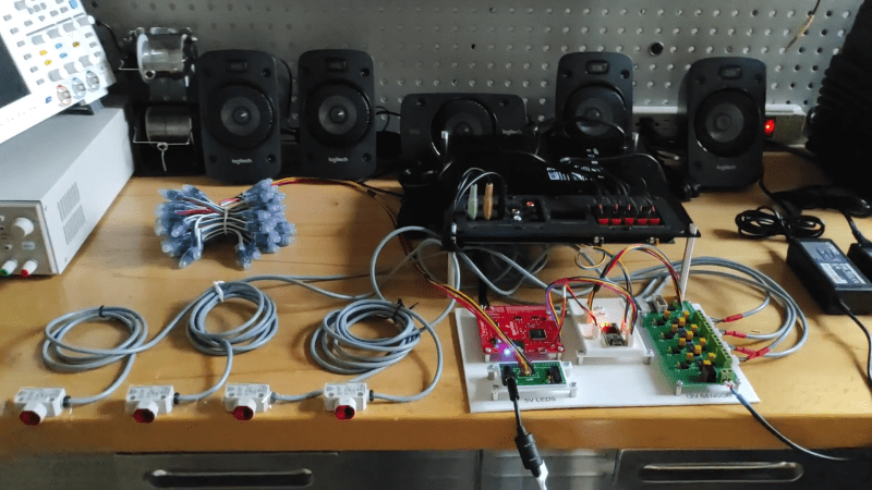
The Logitech Z906 is a well-rounded 5.1 surround sound system. It’s capable of putting out 1000W in peak power, and can decode Dolby Digital and DTS soundtracks as you’d expect. It’s intended to be used as the heart of a home cinema system and used with a central command console. However, [zarpli] figured out the device’s serial secrets and can now run the device in a standalone manner.
As it turns out, the Z906 uses a main control console that speaks to the rest of the hardware over a DE15 connector (also known as the DB-15). [zarpli] realized that the hardware could instead be commanded by just about any device with a serial port. Thus, a library was whipped up that can be readily used with an Arduino to control all the major functions of the Z906. Everything from volume levels to effect modes and channel assignments can be commanded by microcontroller. As a finale, [zarpli] shows off the hardware playing a multi-channel composition without the console connected, with his own hardware running the show instead.
If you’ve got a Logitech Z906 or similar unit that you wish to automate, you might find this work useful. It’s also a good inspiration for anyone contemplating hacking away at the console ports on other hardware. Video after the break.
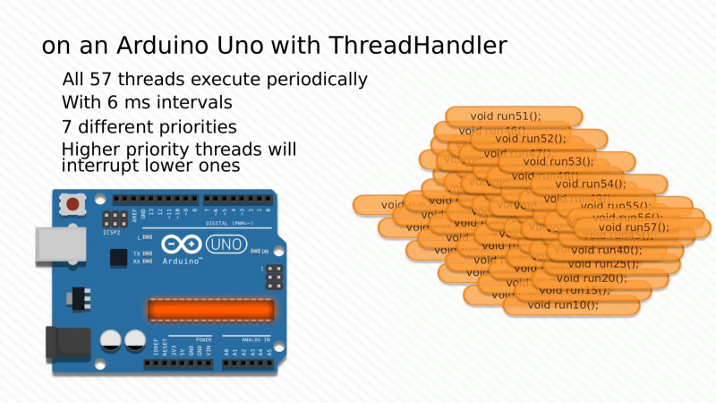
When one thinks of the Arduino Uno, one thinks of a capable 8-bit microcontroller platform that nonetheless doesn’t set the world alight with its performance. Unlike more modern parts like the ESP32, it has just a single core and no real multitasking abilities. But what if one wanted to run many threads on an Uno all at once? [Adam] whipped up some code to do just that.
Threads are useful for when you have multiple jobs that need to be done at the same time without interfering with each other. The magic of [Adam]’s ThreadHandler library is that it’s designed to run many threads and do so in real time, with priority management as well. On the Arduino Uno, certainly no speed demon, it can run up to 57 threads concurrently at 6ms intervals with a minumum timing error of 556 µs and a maximum of 952 µs. With a more reasonable number of 7 threads, the minimum error drops to just 120 µs. Each thread comes with an estimated overhead of 1.3% CPU load and 26 bytes of RAM usage.
While we struggle to think of what we could do with more than a handful of threads on an Arduino Uno, we’re sure you might have some ideas – sound off in the comments. ThreadHandler is available for your perusal here, and runs on SAMD21 boards as well as any AVR-based boards that are compatible with TimerOne. We’ve seen other work in the same space before, such as ChibiOS for the Arduino platform. Video after the break.
The readability of your code can make the difference between your project being a joy to work on, or an absolute headache. This goes double when collaborating with others. Having easily parsed code reduces your cognitive load and makes solving problems easier. To try and help with this, [PTS93] developed the Stator library to make certain common tasks simpler to read.
The aim of the library is to get rid of piles of state tracking variables and endless if/else statements – hence the name. It’s designed primarily for the Arduino IDE but doesn’t have any dependencies on the API, so can be used in other C++ environments. It comes with a variety of neat tools for common jobs, such as reading an analog sensor with hysteresis around a trigger point, as well as easy ways to track state changes across multiple variables. By using basic English terms instead of condition checks and mathematical operators, it can make things more readable and easier to follow.
Amazon Dash is a handy service, and when Amazon released their AWS IoT platform, [Brian Carbonette] felt that it left out all the hardware hackers from the tinkering fun. Seeking justice, he put together a guide for an Arduino Dash button aimed at hardware hackers and those who are still easing into the world.
For his build, [Carbonette] used an Arduino MKR1000, laying out a few different configuration options for building your button. He has also gone to great lengths to help all comers tackle the Arduino-Dash API communication process by building an AmazonDRS Arduino Library, which handles all the “boring details,” so you can focus on the hardware. With the warning that the software-side setup is tedious the first time around, [Carbonette] has included a detailed manual for setting up the aforementioned AmazonDRS library, some example code, and a breakdown thereof. He also suggests implementing other features — such as a notification if the item is out of stock on Amazon — to tie the project together.
[Carbonette] has also provided some external resources on various aspects of the project for those seeking greater depth and ideas for expanding beyond. Next thing you know you’ll be summoning Ubers and finding your misplaced phone.
Fun with Arduino contest entry submitted by Gamaiel Zavala.
There are other Instructables about building LED cubes, this one is different for several reasons:
1. It’s built with a low number of off-the-shelf components and hooks up directly to the Arduino.
2. A clear, easy to reproduce circuit diagram is provided with plenty of photos.
3. A unique approach is used for the software which makes programming the cube easier and more expressive.
This step largely follows the LED Cube 4×4x4 but we’ll be building a 3×3x3 cube instead. A cube of this size is about as big as it gets without introducing additional circuitry and complexity. We’ll need a total of 27 LEDs that will be grouped into three sets of nine.
Each set of nine LEDs will share a common connection amongst their cathodes (negative leads). I’ll refer to each of these sets as a “level”. Each of the nine LEDs on a level is connected to the corresponding LED on the other two levels through their anodes (positive leads). These will be referred to as “columns”. If that didn’t make sense it will become self explanatory as we build the cube.
To start we’ll use a drill to create a jig out of a small piece of scrap wood. The jig will hold the LEDs in place while we solder them. I decided to space the holes around 5/8 of an inch apart (~15 mm) but the exact distance isn’t critical. The hole should have a tight fit around the LED since we don’t want them to move around while soldering.
Preparing the LEDs
Once the jig is done we’re going to bend the cathode of each LED in a 90 degree angle. The cathode is identifiable in three ways: 1) It’s the shorter leg, 2) It’s on the flat side of a round LED, 3) it’s connected to the larger piece inside the LED. Make sure you bend the cathode in the same direction for all of the LEDs.
Now we’re ready to begin soldering.
Solder the LEDs
LEDs ready to solder.
First place nine of the LEDs in your newly built jig. Position them so that the legs point in the same counter-clockwise direction. The photos show the cathode pointing clockwise with the anode facing out, but I’d turn the LEDs around if I did it again in order to keep the leg from obstructing the view of the LED.
Solder the sides together, one pair on each side. Use small clips to keep the legs clamped together while applying the solder.
Once each of the four sides are soldered, move the clips to hold the corners together and apply solder to each. Lastly, solder the cathode of the middle LED to one of the sides and trim away the excess.
Repeat three times.
You should now have three sets of nine LEDs. Position two of the sets one on top of the other. Keep the distance equal to the spacing already established between LEDs. Once you’re comfortable with the spacing you can clamp each set of legs using two clips, one in each direction, to keep the legs firmly in place while soldering. You may need to bend around a LED to get a good connection. Solder each of the nine pairs, one at a time.
Do this one more time and you’re done with the cube.
Place the cube on one side of the the perfboard. Make sure the nine legs are positioned apart evenly while you guide each one through a hole. My board has five holes between each set of legs. You want to leave as much room as possible on the other end of the perfboard to fit the various components.
Add a few clips to hold the legs in place once you’re happy with the positioning. Leave plenty of leg poking through the bottom since this will make it easier to solder the resistors later. Turn the board over and solder each of the legs to keep them in place. Flip the cube back over once all the legs have been soldered.
Lastly we need to solder a lead from each of the levels down through the bottom of the board. Strip a piece of solid wire and bend a small hook on one end. Hang the hook on one of the center LEDs legs and guide it through a hole on the perfboard. Solder the hook end to keep the wire in place. Repeat again for the other two levels.
The next step is to build the rest of the circuit.
Build the Circuit
LED 3x3x3 Cube
The circuit is pretty simple. Each of the nine columns will connect to a pin on the Arduino through a current limiting resistor. Each of the three levels connects to ground via a PNP transistor when activated by an Arduino pin.
We’ll be using 12 output pins total on the Arduino but there are 18 LEDs to power. The trick is that only a single level can be lit at a time. When a level is connected to ground, each of the LEDs on that level can be powered individually through one of the nine other Arduino pins. If we light the levels fast enough it will appear as if all three levels are lit at the same time.
Let’s build the circuit.
The first step is to prepare the nine current limiting resistors. I’m using 220 ohms per pin which will draw around 22mA. The value may vary depending on the LEDs that are being used but stay between about 135 and 470 ohms. Each pin is capable of sourcing up to 40mA.
In order to save room we want to solder the resistors in a vertical position. Bend one lead down so that both leads are parallel to each other. Do this for all nine of the resistors.
Once the resistors are ready we’ll solder them one by one. To make it easy we’re going to solder the resistor leads directly to the other components instead of using a separate wire for each. One end of the resistor will connect to a column and the other will connect to a header. Start with the first row of LEDs which is closest to the resistors and work your way back.
Once each row is finished you can use a small piece of tape to isolate the overlapping leads in order to prevent a short. Refer to the photos and diagram to see what this will look like once it’s finished.
Now that the columns are out of the way, the next step is to solder the components which control the levels. The base of a NPN transistor will be activated by an Arduino pin through a current limiting resistor of 22k (or thereabouts). This will connect the corresponding level to ground which will allow current to flow through the LEDs. Refer to the photos and diagram.
The circuit is now complete, time to move on to the software!
Using the Software
I was found a few code examples to control LED cubes on the net. They all required large arrays of binary or hex data to instruct the LEDs. I figured that there must be an easier way to program a cube so I set out to write my own software.
The first decision was to make the software mirror the hardware. That meant addressing each LED by column and level instead of using raw port data or the traditional x, y, z. The second decision was to start with basic functions, like turning a single light on or off, and building up from there.
Lastly I decided to introduce two features that are useful for effects. One is a buffer feature which allows the basic functions to build up more complex patterns, and the other is a sequence function which lights an array of lights one at a time or all at once.
This grew organically as procedural code and loose functions. It was very easy from there to follow the library tutorial in order to encapsulate the functionality into a class and create a reusable Arduino library.
Planet Arduino is, or at the moment is wishing to become, an aggregation of public weblogs from around the world written by people who develop, play, think on Arduino platform and his son. The opinions expressed in those weblogs and hence this aggregation are those of the original authors. Entries on this page are owned by their authors. We do not edit, endorse or vouch for the contents of individual posts. For more information about Arduino please visit www.arduino.cc
You are currently browsing the archives for the Arduino Library category.