He was inspired by several other cubes like [Chr's], and the Borg cube by [Das-Labour]. The project makes use of an Arduino Mega 2560 R3 to drive the 512-LED array, and an Arduino Uno to take care of the sound effects during game play. It’s kind of like Space Invaders — but in 3D!
Complexity of building and wiring it aside, [Anred] has provided great instructions and the code for the entire project, so if you’re looking to recreate it or something like it, you can! It’s also entered in an Instructable’s contest right now, so if you like it, we’re sure he’d appreciate the votes.
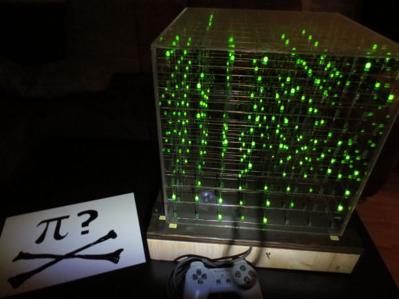
Sure, the physical build itself looks great, but it’s what [Michael] did with the firmware that impresses us the most. He’s using an Arduino Mega to drive the 7x7x7 cube and manages to squeeze out what he calls 142 frames per second with the setup. We’re not sure FPS is the right measurement, as we believe it’s the multiplexing rate that he’s trying to describle. It takes 144 uS to scan the entire matrix once. He performs the scan seven times per frame and the result is a flicker-free appearance, even to cameras.
You can see a video demonstration after the break. Since [Michael] emailed us directly with more details about the build we’ve pasted those below the fold as well.
If you’re looking for a more entry-level Arduino LED cube this 4x4x4 project is just the thing.
The cube is able to process 142 frames per second, that is, 1 frame every 7 milliseconds. Within this time period, it loops through a still frame 7 times (Each cycle of POV lasts 144 microseconds). This is able to compensate for flickering during video recording, allowing all camera’s to record fluid video without distortion.
The cube itself is controlled with an Arduino Mega 2560. For each frame in memory, the Arduino reads and bit shifts 49 bytes of data for an encoded duration. This allows for the cube to be applied to a variety of purposes, from text display to effects to music visualisation.
The frames were generated through complex Processing scripts, allowing for a multitude of operations such as shifting in any direction (seen in the rain effect), and an edge shift (seen in the scrolling text around the outside of the cube). These scripts were used to perform the basis of calculations for fireworks, as well as sine waves in 1, 2 & 3 dimensions (seen in the video).
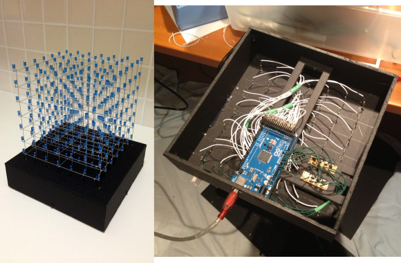
In this cube the supporting structure was made 0.9 mm galvanised steel wire, straightened by stretching the wire. The 5mm Blue LED’s are positioned 30mm apart, with the anodes being attached to the verticals (white wires in the image below) & the cathodes are attached to the horizontal layers (green wires in the image below – bottom right – shown passing through NPN transistors). The Arduino Mega 2560 R3 is positioned on a suspended platform, with the anodes controlled on the Digital Pins as opposed to the cathodes on remapped AnalogInputs.
Fun with Arduino contest entry submitted by Gamaiel Zavala.
There are other Instructables about building LED cubes, this one is different for several reasons:
1. It’s built with a low number of off-the-shelf components and hooks up directly to the Arduino.
2. A clear, easy to reproduce circuit diagram is provided with plenty of photos.
3. A unique approach is used for the software which makes programming the cube easier and more expressive.
This step largely follows the LED Cube 4×4x4 but we’ll be building a 3×3x3 cube instead. A cube of this size is about as big as it gets without introducing additional circuitry and complexity. We’ll need a total of 27 LEDs that will be grouped into three sets of nine.
Each set of nine LEDs will share a common connection amongst their cathodes (negative leads). I’ll refer to each of these sets as a “level”. Each of the nine LEDs on a level is connected to the corresponding LED on the other two levels through their anodes (positive leads). These will be referred to as “columns”. If that didn’t make sense it will become self explanatory as we build the cube.
To start we’ll use a drill to create a jig out of a small piece of scrap wood. The jig will hold the LEDs in place while we solder them. I decided to space the holes around 5/8 of an inch apart (~15 mm) but the exact distance isn’t critical. The hole should have a tight fit around the LED since we don’t want them to move around while soldering.
Preparing the LEDs
Once the jig is done we’re going to bend the cathode of each LED in a 90 degree angle. The cathode is identifiable in three ways: 1) It’s the shorter leg, 2) It’s on the flat side of a round LED, 3) it’s connected to the larger piece inside the LED. Make sure you bend the cathode in the same direction for all of the LEDs.
Now we’re ready to begin soldering.
Solder the LEDs
LEDs ready to solder.
First place nine of the LEDs in your newly built jig. Position them so that the legs point in the same counter-clockwise direction. The photos show the cathode pointing clockwise with the anode facing out, but I’d turn the LEDs around if I did it again in order to keep the leg from obstructing the view of the LED.
Solder the sides together, one pair on each side. Use small clips to keep the legs clamped together while applying the solder.
Once each of the four sides are soldered, move the clips to hold the corners together and apply solder to each. Lastly, solder the cathode of the middle LED to one of the sides and trim away the excess.
Repeat three times.
You should now have three sets of nine LEDs. Position two of the sets one on top of the other. Keep the distance equal to the spacing already established between LEDs. Once you’re comfortable with the spacing you can clamp each set of legs using two clips, one in each direction, to keep the legs firmly in place while soldering. You may need to bend around a LED to get a good connection. Solder each of the nine pairs, one at a time.
Do this one more time and you’re done with the cube.
Place the cube on one side of the the perfboard. Make sure the nine legs are positioned apart evenly while you guide each one through a hole. My board has five holes between each set of legs. You want to leave as much room as possible on the other end of the perfboard to fit the various components.
Add a few clips to hold the legs in place once you’re happy with the positioning. Leave plenty of leg poking through the bottom since this will make it easier to solder the resistors later. Turn the board over and solder each of the legs to keep them in place. Flip the cube back over once all the legs have been soldered.
Lastly we need to solder a lead from each of the levels down through the bottom of the board. Strip a piece of solid wire and bend a small hook on one end. Hang the hook on one of the center LEDs legs and guide it through a hole on the perfboard. Solder the hook end to keep the wire in place. Repeat again for the other two levels.
The next step is to build the rest of the circuit.
Build the Circuit
LED 3x3x3 Cube
The circuit is pretty simple. Each of the nine columns will connect to a pin on the Arduino through a current limiting resistor. Each of the three levels connects to ground via a PNP transistor when activated by an Arduino pin.
We’ll be using 12 output pins total on the Arduino but there are 18 LEDs to power. The trick is that only a single level can be lit at a time. When a level is connected to ground, each of the LEDs on that level can be powered individually through one of the nine other Arduino pins. If we light the levels fast enough it will appear as if all three levels are lit at the same time.
Let’s build the circuit.
The first step is to prepare the nine current limiting resistors. I’m using 220 ohms per pin which will draw around 22mA. The value may vary depending on the LEDs that are being used but stay between about 135 and 470 ohms. Each pin is capable of sourcing up to 40mA.
In order to save room we want to solder the resistors in a vertical position. Bend one lead down so that both leads are parallel to each other. Do this for all nine of the resistors.
Once the resistors are ready we’ll solder them one by one. To make it easy we’re going to solder the resistor leads directly to the other components instead of using a separate wire for each. One end of the resistor will connect to a column and the other will connect to a header. Start with the first row of LEDs which is closest to the resistors and work your way back.
Once each row is finished you can use a small piece of tape to isolate the overlapping leads in order to prevent a short. Refer to the photos and diagram to see what this will look like once it’s finished.
Now that the columns are out of the way, the next step is to solder the components which control the levels. The base of a NPN transistor will be activated by an Arduino pin through a current limiting resistor of 22k (or thereabouts). This will connect the corresponding level to ground which will allow current to flow through the LEDs. Refer to the photos and diagram.
The circuit is now complete, time to move on to the software!
Using the Software
I was found a few code examples to control LED cubes on the net. They all required large arrays of binary or hex data to instruct the LEDs. I figured that there must be an easier way to program a cube so I set out to write my own software.
The first decision was to make the software mirror the hardware. That meant addressing each LED by column and level instead of using raw port data or the traditional x, y, z. The second decision was to start with basic functions, like turning a single light on or off, and building up from there.
Lastly I decided to introduce two features that are useful for effects. One is a buffer feature which allows the basic functions to build up more complex patterns, and the other is a sequence function which lights an array of lights one at a time or all at once.
This grew organically as procedural code and loose functions. It was very easy from there to follow the library tutorial in order to encapsulate the functionality into a class and create a reusable Arduino library.
Planet Arduino is, or at the moment is wishing to become, an aggregation of public weblogs from around the world written by people who develop, play, think on Arduino platform and his son. The opinions expressed in those weblogs and hence this aggregation are those of the original authors. Entries on this page are owned by their authors. We do not edit, endorse or vouch for the contents of individual posts. For more information about Arduino please visit www.arduino.cc
You are currently browsing the archives for the LED cube category.