Posts | Comments

Planet Arduino

Archive for the ‘led hacks’ Category

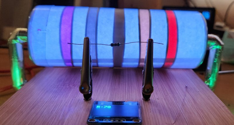
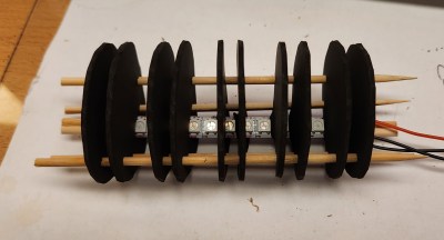
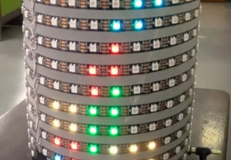
You’ve probably played some version of Tetris, but [the Center for Creative Learning] has a different take on it. Their latest version features a cylindrical playing field. While it wouldn’t be simple to wire up all those LEDs, it is a little easier, thanks to LED strips. You can find the code for the game on GitHub.

In all, there are 5 LED strips for a display and 13 strips for the playing area, although you can adjust this as long as there are at least 10 rows. The exact number of LEDs will depend on the diameter of the PVC pipe you build it on.

Using a PS2 controller, the games allow you to play a full-cylinder or in a half-cylinder mode. We were hoping they’d have put up a video showing the gameplay, but we couldn’t find it.

We couldn’t help but think that this would make an excellent display for many purposes. You might even be able to design different games for it.

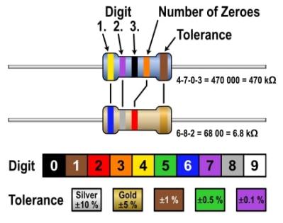
We’ve seen full-circle Tetris, but it is hardly the same idea. If you want just plain Tetris, you could break out your transistor tester.

The Moon has fascinated humanity for centuries. These days, though, it’s a trial and a bore to go outside and stare upwards to check on the natural satellite. Instead, why not bring the Moon to your bedside with this rotating phase lamp?

The build comes to us from [payasa_manandhar], who did a good job of replicating the Moon in both form and function. It’s based around a lithophane of the lunar surface, which adequately duplicates the Moon’s grey pockmarked visage thanks to topographical data sourced from NASA. It looks a treat when backlit from the inside. However, this is no mere ornamental lamp. With the aid of a stepper motor controlled by an Arduino, a shade inside the lamp actually rotates to shadow the Moon as per the appropriate phase.

It’s a build that is both fun and educational, in both the electronic and astronomical disciplines. We’ve seen some other great Moon lamps before, too.

Of course, there’s nothing unusual about using 7-segment displays, especially in a clock. However, [Edison Science Corner] didn’t buy displays. Instead, he fabricated them from a PCB using 0805 LEDs for the segments. You can see the resulting clock project in the video below.

While the idea is good, we might have been tempted to use a pair of LEDs for each segment or used a diffuser to blur the LEDs. The bare look is nice, but it can make reading some numerals slightly confusing.

The remainder of the project is what you’d expect, a 3D-printed case and an Arduino Nano coupled with a DS1307 make the clock part work.

Honestly, with a few changes, we’d like to make up some of these boards for other kinds of custom displays. We can imagine a PCB where the bottoms of the display elements are right at the edge of the board instead of on stalks. You could even create a 14-segment display (we used to call these British flag displays) to make custom text messages. Of course, you can also make custom electroluminescent displays on a PCB reasonably easily, too.

A two picture montage of a boy wearing a sonic the hedgehog costume with LEDs in them. The left picture is at night with the boy wearing sunglasses and a face mask with the sonic costume head piece lit up. The right picture is during the day with the boy wearing a face mask, holding a plastic pu mpkin bucket for candy and wearing a lit up sonic the hedgehog costume in the front yard of a house.

[Wentworthm] couldn’t say no to his son’s plea for a Sonic the Hedgehog costume for Halloween but also couldn’t resist sprucing it up with LEDs either. The end result is a surprisingly cool light up Sonic the Hedgehog costume.

a picture of a breadboard with an Arduino Nano on it, with wires going out to 3d printed tear dropped shapes that have LED strips in them, with some LED strips on.

After some experimentation, [Wentworthm] ordered two costumes and ended up mixing and matching the head piece of one with the body suit of the other. For the head, [Wentworthm] created six 3D printed “quills” that had slots for the WS2812B LED strips to slide into and diffuse out the sides, with each quill sliding into the folds of the Sonic head “spikes”. Sewn strips of cloth were used to house the LED strips that were placed down the sides of the costume. An additional 3D printed switch housing was created to allow for a more robust interface to the two push buttons to activate the LEDs. An Arduino Nano, soldered to a protoboard, was used to drive the LED strips with a USB battery pack powering the whole project.

[Wentworthm] goes into more detail about the trials and errors, so the post is definitely worth checking out for more detail on the build. Halloween is always a great source of cool costumes and we’ve featured some great ones before, like a light up crosswalk costume to making a giant Gameboy colour costume.

Video after the break!

"The Great Resistor" color code illumination project

With surface-mount components quickly becoming the norm, even for homebrew hardware, the resistor color-code can sometimes feel a bit old-hat. However, anybody who has ever tried to identify a random through-hole resistor from a pile of assorted values will know that it’s still a handy skill to have up your sleeve. With this in mind, [j] decided to super-size the color-code with “The Great Resistor”.

Resistor color code from Wikipedia with white background
How the resistor color-code bands work

At the heart of the project is an Arduino Nano clone and a potential divider that measures the resistance of the test resistor against a known fixed value. Using the 16-bit ADC, the range of measurable values is theoretically 0 Ω to 15 MΩ, but there are some remaining issues with electrical noise that currently limit the practical range to between 100 Ω and 2 MΩ.

[j] is measuring the supply voltage to help counteract the noise, but intends to move to an oversampling/averaging method to improve the results in the next iteration.

The measured value is shown on the OLED display at the front, and in resistor color-code on an enormous symbolic resistor lit by WS2812 RGB LEDs behind.

Inside view of the great resistor showing WS2812 LEDs and baffle plates
Inside The Great Resistor, the LEDs and baffle plates make the magic work

Precision aside, the project looks very impressive and we like the way the giant resistor has been constructed. It would look great at a science show or a demonstration. We’re sure that the noise issues can be ironed out, and we’d encourage any readers with experience in this area to offer [j] some tips in the comments below. There’s a video after the break of The Great Resistor being put through its paces!

If you want to know more about the history of the resistor color code bands, then we have you covered.  Alternatively, how about reading the color code directly with computer vision?

A diagram showing an LED on the left, a lever-style plumbing valve in the center, and an Arduino Uno on the right.

Input devices that can handle rough and tumble environments aren’t nearly as varied as their more fragile siblings. [Alastair Aitchison] has devised a brilliant way of detecting inputs from plumbing valves that opens up another option. (YouTube) [via Arduino Blog]

While [Aitchison] could’ve run the plumbing valves with water inside and detected flow, he decided the more elegant solution would be to use photosensors and an LED to simplify the system. This avoids the added cost of a pump and flow sensors as well as the questionable proposition of mixing electronics and water. By analyzing the change in light intensity as the valve closes or opens, you can take input for a range of values or set a threshold for an on/off condition.

[Aitchison] designed these for an escape room, but we can see them being great for museums, amusement parks, or even for (train) simulators. He says one of the main reasons he picked plumbing valves was for their aesthetics. Industrial switches and arcade buttons have their place, but certainly aren’t the best fit in some situations, especially if you’re going for a period feel. Plus, since the sensor itself doesn’t have any moving parts, these analog inputs will be easy to repair should anything happen to the valve itself.

If you’re looking for more unusual inputs, check out the winners of our Odd Inputs and Peculiar Peripherals contest or this typewriter that runs Linux.

One of the problems with a classic Turing machine is the tape must be infinitely long. [Mark’s] Turing Ring still doesn’t have an infinite tape, but it does make it circular to save space. That along with a very clever and capable UI makes this one of the most usable Turing machines we’ve seen. You can see a demo in the video below.

The device uses an Arduino Nano, a Neopixel ring, an encoder, and a laser-cut enclosure that looks great. The minimal UI has several modes and the video below takes you through all of them.

You can even store tapes to EEPROM or the serial port, so that’s even more practical. Of course, you might wonder what practicality is a Turing machine? The honest answer is not much, but on the bright side, this one also has a clock mode so even when you aren’t explaining how a Turing machine works, it will make a good conversation piece.

We were impressed with the lettering on the case in addition to the simplicity of the user interface. [Mark] had won the LED ring in a competition so the total cost of this — to him — was low, but it wouldn’t be too much even if you bought all the pieces.

This one is certainly more compact than the last Turing machine we looked at. If you need a refresher on Turing machines and why they matter, here’s some reading for you.

[Fearless Night]’s slick dual hourglass doesn’t just simulate sand with LEDs, it also emulates the effects of gravity on those simulated particles and offers a few different mode options.

The unit uses an Arduino (with ATMEGA328P) and an MPU-6050 accelerometer breakout board to sense orientation and movement, and the rest is just a matter of software. Both the Arduino and the MPU-6050 board are readily available and not particularly expensive, and the LED matrix displays are just 8×8 arrays of red/green LEDs, each driven by a HT16K33 LED controller IC.

The enclosure and stand are both 3D-printed, and a PCB not only mounts the components but also serves as a top cover, with the silkscreen layer of the PCB making for some handy labels. It’s a clever way to make the PCB pull double-duty, which is a technique [Fearless Night] also used on their earlier optical theremin design.

Those looking to make one of their own will find all the design files and source code handily available from the project page. It might not be able to tell time in the classical sense, but seeing the hourglass displays react to the device’s orientation is a really neat effect.

Etch-a-sketch made with LEDs

We never did crack open our Etch-a-Sketch, but we did scrape out a window large enough to really check out the mechanism inside. [MrLangford] is bringing the Etch-a-Sketch into the 21st century while at the same time, bringing an even bigger air of mystery, at least for the normies.

Instead of scraping aluminum powder off of plastic by driving a stylus on an x-y gantry with a pair of knobs, this bad boy uses rotary encoders to move the cursor around and put down squares of colored light. The familiar movements are there — the left knob moves the cursor left and right, and the right knob moves it up and down. But this wouldn’t be a 21st century toy without newfangled features. Push the left encoder down and it cycles through eight color choices, or push the right one down to go through them backwards. We hope one of the colors is setting it back to darkness in case you screw up. And while we’re dreaming up improvements, it would be awesome to add an accelerometer so you could shake it clear like a standard Etch-a-Sketch.

Inside the requisite red enclosure with white knobs are an Arduino Nano and a 16×16 RGB LED matrix. The enclosure is four sheets of 6mm MDF glued together, and we like the use of protoboard to distribute GND and 5 V in the name of keeping the thing slim.

If you’re not much of an artist, here’s a TV-sized Etch-a-Sketch build that can draw by itself.


  • Newsletter

    Sign up for the PlanetArduino Newsletter, which delivers the most popular articles via e-mail to your inbox every week. Just fill in the information below and submit.

  • Like Us on Facebook