Biometric identification and authentication is big business. As an example, consider Apple’s Face ID technology, which has made strong smartphone security both user friendly and readily available. But Face ID requires substantial hardware and computational power to work, which makes it ill-suited for applications where cost is a major concern. To fill that gap in the market, an international team of researchers developed technology called LIPAuth that can identify people by the light reflected by their hands.
LIPAuth stands for “Light Intensity Pattern Authentication,” which accurately describes how this technology works. It measures the intensity of different light patterns as they reflect off of a person’s hand. As it turns out, those reflections are unique to the individual, just like a fingerprint. The reflected light depends on the shape of the hand, its unique crevasses and wrinkles, skin tone and capillary structure, and the way in which the individual holds their hand during scanning. By projecting different light patterns, LIPAuth can gather a large set of data points to compare for authorization.
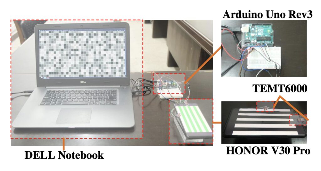
The prototype built to test this concept consisted of an Arduino Uno board, an LCD screen from an HONOR V30 Pro smartphone, a TEMT6000 light sensor, and a Dell laptop. The LCD shows different patterns, which reflect off of the user’s hand. The Arduino monitors the intensity of the reflected through the TEMT6000. The Arduino then sends the data to the Dell laptop, which analyzes the information and compares it to that of authorized users.
In testing, the research team determined that LIPAuth could recognize users with accuracy higher than 99%. It is also quite resilient to attacks from unauthorized users. Because of the low requirements and high accuracy, LIPAuth could be very useful for low-cost biometric authentication.
At Arduino, we are hard at work to keep improving the security of our hardware and software products, and we would like to run you through how our IoT Cloud service works.
The open-source library ArduinoBearSSL for implementing TLS protocol on Arduino boards;
A hardware secure element (Microchip ATECCX08A) to guarantee authenticity and confidentiality during communication;
A device certificate provisioning process to allow client authentication during MQTT sessions.
ArduinoBearSSL
In the past, it has been challenging to create a complete SSL/TLS library implementation on embedded (constrained) devices with very limited resources.
An Arduino MKR WiFi 1010, for instance, only has 32KB of RAM while the standard SSL/TLS protocol implementations were designed for more powerful devices with ~256MB of RAM.
As of today, a lot of embedded devices still do not properly implement the full SSL/TLS stack and fail to implement good security because they misuse or strip functionalities from the library, e.g. we found out that a lot of off-brand boards use code that does not actually validate the server’s certificate, making them an easy target for server impersonation and man-in-the-middle attacks.
Security is paramount to us, and we do not want to make compromises in this regard when it comes to our offering in both hardware and software. We are therefore always looking at “safe by default” settings and implementations.
Particularly in the IoT era, operating without specific security measures in place puts customers and their data at risk.
This is why we wanted to make sure the security standards adopted nowadays in high-performance settings are ported to microcontrollers (MCUs) and embedded devices.
Back in 2017, while looking at different SSL/TLS libraries supporting TLS 1.2 and modern cryptography (something that could work with very little RAM/ROM footprint, have no OS dependency, and be compatible with the embedded C world), we decided to give BearSSL a try.
BearSSL: What is it?
BearSSL provides an implementation of the SSL/TLS protocol (RFC 5246) written in C and developed by Thomas Pornin.
Optimized for constrained devices, BearSSL aims at small code footprint and low RAM usage. As per its guiding rules, it tries to find a reasonable trade-off between several partly conflicting goals:
Security: defaults should be robust and using patently insecure algorithms or protocols should be made difficult in the API, or simply not possible;
Interoperability with existing SSL/TLS servers;
Allowing lightweight algorithms for CPU-challenged platforms;
Be extensible with strong and efficient implementations on big systems where code footprint is less important.
BearSSL and Arduino
Our development team picked it as an excellent starting point for us to make BearSSL fit in our Arduino boards focusing on both security and performance.
The firmware developers team worked hard on porting BearSSL to Arduino bundling it together as a very nice and open-source library: ArduinoBearSSL.
Because the computational effort of performing a crypto algorithm is high, we decided to offload part of this task to hardware, using a secure element (we often call it a “cypto chip”). Its advantages are:
Making the computation of cryptography operations faster;
You are not forced to use all the available RAM of your device for these demanding tasks;
Allows storing private keys securely (more on this later);
It provides a true random number generator (TRNG).
How does the TLS protocol work?
TLS uses both asymmetric and symmetric encryption. Asymmetric encryption is used during the TLS handshake between the client and the server to exchange the shared session key for communication encryption. The algorithms commonly used in this phase are based on Rivest-Shamir-Adleman (RSA) or Diffie-Hellman algorithms.
TLS 1.2 Handshake flow
After the TLS handshake, the client and the server both have a session key for symmetric encryption (e.g. algorithms AES 128 or AES 256).
The TLS protocol is an important part of our IoT Cloud security model because it guarantees an encrypted communication between the IoT devices and our servers.
The secure element
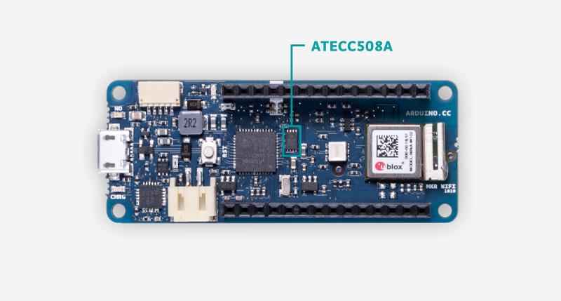
In order to save memory and improve security, our development team has chosen to introduce a hardware secure element to offload part of the cryptography algorithms computational load, as well as to generate, store, and manage certificates. For this reason, on the Arduino MKR family, Arduino Nano 33 IoT and Arduino Uno WiFi Rev2, you will find the secure element ATECC508A or ATECC608A manufactured by Microchip.
How do we use the secure element?
A secure element is an advanced hardware component able to perform cryptographic functions, we have decided to implement it on our boards to guarantee two fundamental security properties in the IoT communication:
Authenticity: You can trust who you are communicating with;
Confidentiality: You can be sure the communication is private.
Moreover, the secure element is used during the provisioning process to configure the Arduino board for Arduino IoT Cloud. In order to connect to the Arduino IoT Cloud MQTT broker, our boards don’t use a standard credentials authentication (username/password pair). We rather opted for implementing a higher-level authentication, known as client certificate authentication.
How does the Arduino provisioning work?
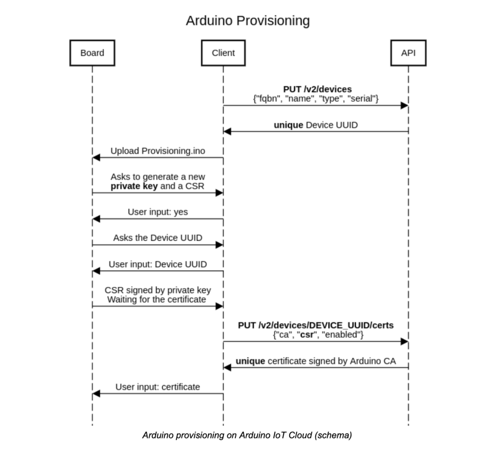
The whole process is possible thanks to an API, which exposes an endpoint a client can interact with.
As you can see in the diagram below, first the Client requests to register a new device on Arduino IoT Cloud via the API, to which the server (API) returns a UUID (Universally Unique IDentifier). At this point, the user can upload the sketch Provisioning.ino to the target board.This code is responsible for multiple tasks:
Generating a private key using the ATECCX08A, and store it in a secure slot that can be only read by the secure element;
Generating a CSR (Certificate Signing Request) using the device UUID as Common Name (CN) and the generated private key to sign it;
Storing the certificate signed by Arduino acting as the authority.
After the CSR generation, the user sends it via the API to the server and the server returns a certificate signed by Arduino. This certificate is stored, in a compressed format, in a slot of the secure element (usually in slot 10) and it is used to authenticate the device to the Arduino IoT Cloud.
Today, we’re announcing a new security feature for our community: two-factor authentication (2FA) on Arduino web services. We have implemented a two-step verification login to arduino.cc, so our users can be sure of their online safety.
If enabled, two-factor authentication offers an additional security layer to the user’s account, so the user can have better protection of their IoT devices connected to Arduino IoT Cloud.We encourage our users to enable 2FA to improve their online safety.
How to enable two-factor authentication
Arduino supports two-factor authentication via authenticator software as Authy or the Google Authenticator. To enable 2FA on your account:
1. Go to id.arduino.cc and click on Activate in the Security frame of your account:
2. Scan the QR code using your own authenticator app (e.g. Authy, Google Authenticator, Microsoft Authenticator, etc.)
3. Now, in your authenticator app, it appears a six-digit code that changes every 30 seconds: copy it in the text field and click Verify.
4. Important: Save your Recovery code in a safe place and do not lose it. If you lose your 2FA codes (e.g. you misplace or break your phone), you can still restore your account using the recovery code. If you lose both 2FA and recovery codes, you will no longer be able to access your account.
5. Great! Now you have the Two-Factor Authentication enabled on your Arduino account.
If you’re the kind of person who has friends, and/or leaves the confines of the basement from time to time, we hear that these “Escape Rooms” are all the rage. Basically you get locked into a room with a couple other people and have to solve various problems and puzzles until you’ve finally made enough progress that they let you out. Which actually sounds a lot like the working conditions here at Hackaday HQ, except they occasionally slip some pizza rolls under the door for us which is nice.
Whichever side you find yourself on in one of these lighthearted hostage situations, knowledge of this multi-tag RFID lock created by [Annaane] may come in handy. By connecting multiple MFRC522 RFID readers to an Arduino Uno, she’s come up with a method of triggering a device (like an electronic door lock) only when the appropriate combination of RFID tags have been arranged. With a little imagination, this allows for some very complex puzzle scenarios which are sure to keep your prisoners enthralled until you can lower the lotion down to them.
Her code allows you to configure the type and number of RFID cards required to trigger one of the Arduino’s digital pins, which usually would be connected to a relay to fire off whatever device you want. The Arduino sketch is also setup to give “hints” to the player by way of a status LED: fast blinking let’s you know the tag scanned is wrong, and slow blinking means you don’t have enough scanned in yet.
The video after the break shows some highlights of the build, as well as a quick demonstration of how both the RFID “combination” and manual override can be used to trigger the attached relay.
Planet Arduino is, or at the moment is wishing to become, an aggregation of public weblogs from around the world written by people who develop, play, think on Arduino platform and his son. The opinions expressed in those weblogs and hence this aggregation are those of the original authors. Entries on this page are owned by their authors. We do not edit, endorse or vouch for the contents of individual posts. For more information about Arduino please visit www.arduino.cc
You are currently browsing the archives for the authentication category.